Leine Linde 901 User manual

Mounting instructions
Montageanleitung
安装说明
Encoder models
Drehgebermodelle
编码器型号
1108704-01, ver. 00
901
903
921
923

3
Contact
Kontakt
联系我们
2
Leine &Linde is a Swedish company dedicated to
production of encoders for heavy duty applications.
Some of the values offered by Leine &Linde are local
technical support and possibility of 24 hours express
delivery.
On our website www.leinelinde.com you can find
• data sheets and other product information
• detailed manuals and configuration files for use
with products with PROFIBUS®, PROFINET®,
EtherCAT®and EtherNet/IPTM.
Leine &Linde ist ein schwedisches Unternehmen,
das sich auf die Produktion von Drehgebern für den
harten Einsatz in Gewerbe und Industrie speziali-
siert hat. Dabei zeichnet sich Leine&Linde unter
anderem durch kundennahen technischen Support
und mögliche 24-Stunden-Expresslieferungen aus.
Auf unserer Homepage www.leinelinde.de finden Sie
• Datenblätter und sonstige Produktinformationen
• ausführliche Handbücher und Konfigurationsda-
teien zur Verwendung von Produkten mit
PROFIBUS®, PROFINET®, EtherCAT®and
EtherNet/IPTM.
莱纳林德是一家专门生产重工况应用编码器的瑞典
公司。莱纳林德提供您的一些价值包括本地技术支
持,以及可能安排 24 小时快递送货。
在我们的网站 www.leinelinde.cn 上,您可以找到
• 数据表与其他产品信息
• 与附带 PROFIBUS®, PROFINET®, EtherCAT®或
EtherNet/IPTM 的产品一起使用时的详细使用手册
和配置文件。
SWEDEN /SVERIGE (Head office)
T +46-(0)152-265 00
F +46-(0)152-265 05
www.leinelinde.se
BRASIL
T +55-19-3291 8425
F +55-19-3367 5658
www.leinelinde.com.br
中国
T +86-(021)-52 58 35 66
F +86-(021)-52 58 35 99
www.leinelinde.cn
DANMARK
www.leinelinde.dk
DEUTSCHLAND
T +49-(0)40-317 675 8-60
F +49-(0)40-317 675 8-65
www.leinelinde.de
ESPAÑA
T +34-93-574 23 02
F +34-93-560 57 60
www.leinelinde.es
INDIA
T +91-11-2617-2504
F +91-11-4058-2516
www.leinelinde.in
ITALIA
T +39-039-596 01 08
F +39-(0)39-971 22 08
www.leinelinde.it
대한민국
T +82-(0)51-746 5420
F +82-(0)51-746 5421
www.leinelinde.co.kr
SUOMI
T +358-(0)9-561 72 00
F +358-(0)9-561 72 020
info@leinelinde.fi
www.leinelinde.fi

5
Contents
Inhalt
目录
1. Risk of bodily injury ____________________ page 7
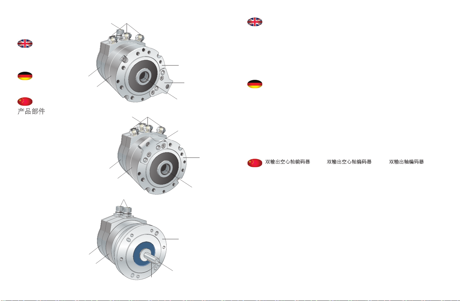
2. Part of the products _________________________ 8
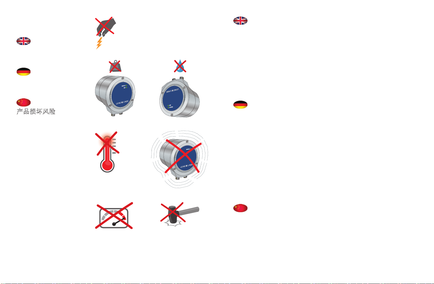
3. Risk of damage to the product ______________ 12
4. Mounting of hollow shaft, torque arm and
solid shaft _________________________________ 14
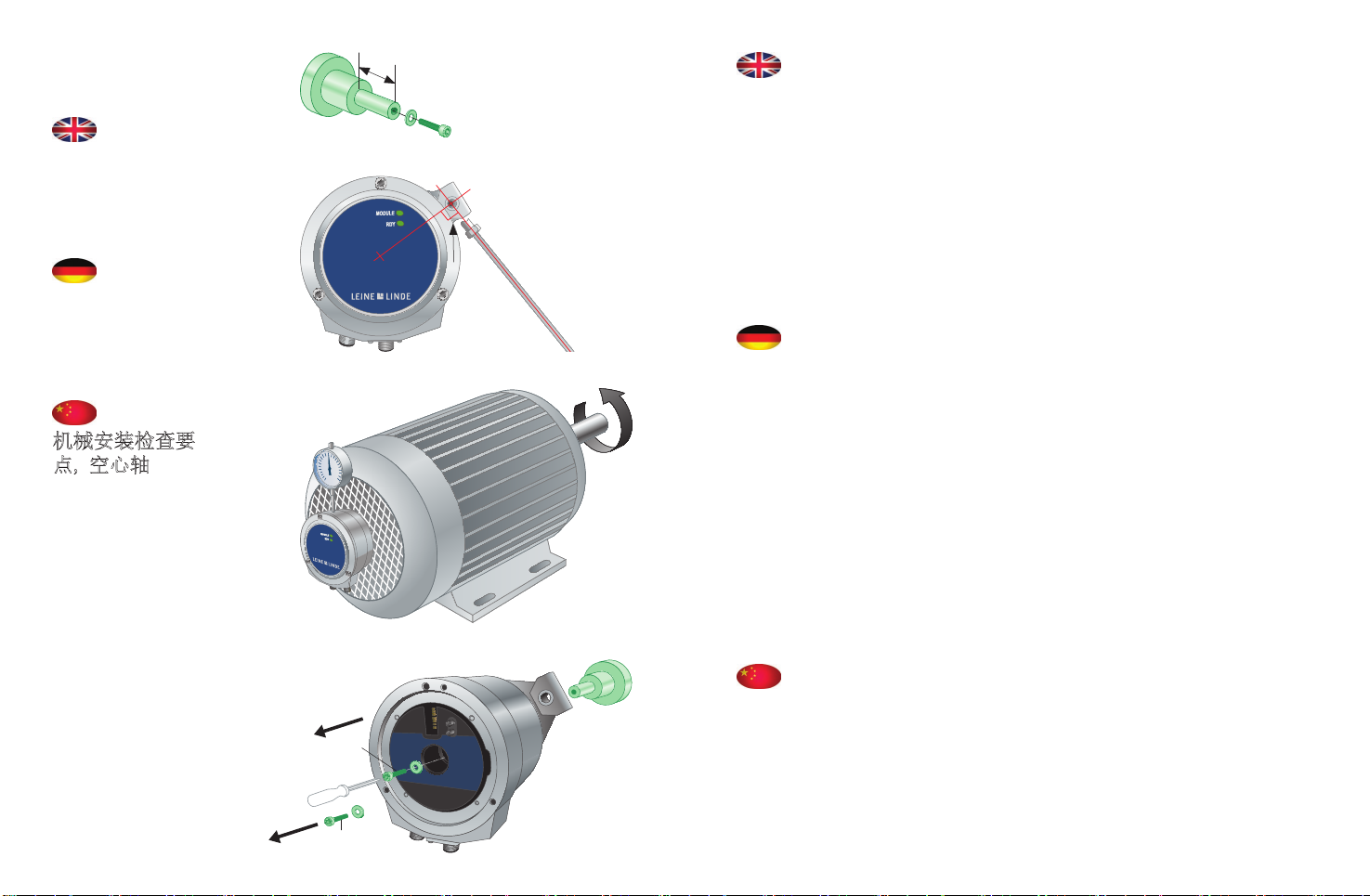
5. Check points for mechanical mounting ______ 16
6. Electrical mounting ________________________ 20
7. Mounting of cable __________________________ 22
8. Mounting of cable, module B ________________ 24
9. Bus settings ________________________________ 26
10. Termination _______________________________ 28
11. Accessories ________________________________ 30
12. Certificates and approvals __________________ 32
1. Verletzungsgefahr ______________________ Seite 7
2. Produktteile _________________________________ 8
3. Beschädigungsgefahr _______________________ 12
4. Montage von Hohlwelle, Drehmomentstütze
und Vollwelle ______________________________ 14
5. Kontrollpunkte bei mechanischer Montage __ 16
6. Elektrische Montage ________________________ 20
7. Kabelmontage______________________________ 22
8. Kabelmontage, Modul B _____________________ 24
9. Bus-Einstellungen __________________________ 26
10. Terminierung ______________________________ 28
11. Zubehör ___________________________________ 30
12. Zertifikate und Zulassungen ________________ 32
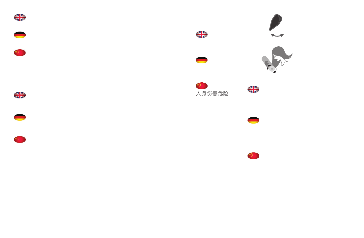
1. 人身伤害危险 _________________________ 第7页
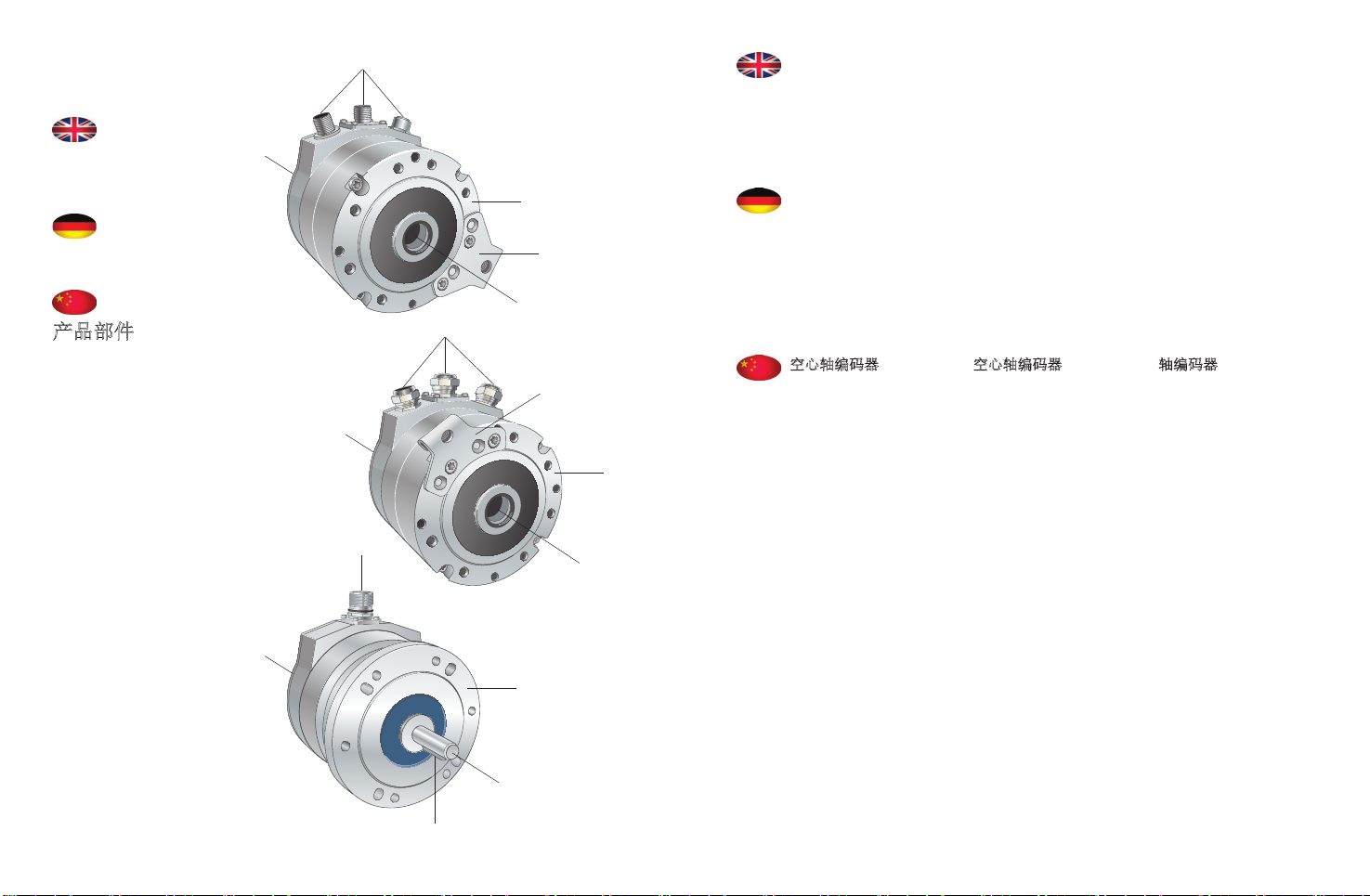
2. 产品部件______________________________ 第8页
3. 产品损坏风险 ________________________ 第12 页
4. 安装空心轴、扭臂和实心轴 ________ 第14 页
5. 机械安装检查要点 ___________________ 第16 页
6. 电气安装 ____________________________ 第20 页
7. 安装电缆 ____________________________ 第22 页
8. 安装电缆、模块 B ____________________ 第24 页
9. 总线设置 ____________________________ 第26 页
10. 端接 _________________________________ 第28 页
11. 附件 _________________________________ 第30 页
12. 执照和认证标准 _____________________ 第32 页
Leine& Linde AB claims copyright on this documen-
tation. It is not allowed to modify, extend or to hand
over to a third party and/or copy this documentation
without written approval from Leine& Linde AB.
Specifications and content in this document are
subject to change without prior notice due to our
continuous strives to improve functionality and
performance of our products.
Leine& Linde AB beansprucht das Urheberrecht an
dieser Dokumentation. Ohne vorherige schriftli-
che Zustimmung von Leine&Linde AB ist es nicht
gestattet, diese Dokumentation zu modifizieren,
zu erweitern, an Dritte weiterzugeben und/oder zu
kopieren.
Spezifikationen und Inhalt dieses Dokuments kön-
nen im Rahmen unseres Ziels, die Funktionalität und
Leistung unserer Produkte fortlaufend zu verbessern,
ohne Vorankündigung geändert werden.
Leine& Linde AB 声明享有本文档的版权。在未经
Leine& Linde AB 书面允许情况下,禁止对本文档进
行修改、给予或转交给第三方和/或复制。
我们致力于持续地提升产品的功能和性能,所以本
文档中的规格和内容可能会在不预先通知的情况下
进行更改。
4

6
PSE 901
PSE 903
PSE 921
PSE 923
PHE 901
PHE 903
PHE 921
PHE 923
PSE 991
PSE 993
PHE 991
PHE 993
The following models are fully covered by these
mounting instructions:
Folgende Modelle werden vollständig von dieser
Montageanleitung abgedeckt:
本安装说明全面涵盖下列型号:
The following models have customised properties
and may deviate slightly from these mounting
instructions:
Folgende Modelle besitzen kundenspezifische
Merkmale und können daher geringfügig von dieser
Montageanleitung abweichen:
下列型号包含有定制特性,可能与本安装说明略
有差异:
1
Risk of bodily
injury
Verletzungs-
gefahr
人身伤害危险
ONOFF
1.1)
1.2)
Important before mounting begins:
1.1 Switch off the power.
1.2 Make sure the machine is at a standstill. The
product is to be mounted on a rotating part that
can cause bodily injury when in motion.
Wichtig! Vor Beginn der Montage:
1.1 Strom ausschalten.
1.2 Sicherstellen, dass die Maschine stillsteht. Das
Produkt wird auf einem rotierenden Teil mon-
tiert, das im Betrieb eine potenzielle Verletzungs-
gefahr darstellt.
安装前注意事项:
1.1 关闭电源。
1.2 确保机器处于停机状态。本产品安装在旋转部
件上,在运动状态下操作可能导致人身伤害。
7

8
2
Parts of the
products
Produktteile
产品部件
9
Hollow shaft encoder
2.1 Hollow shaft
2.2 Torque arm bracket
2.3 Flange
2.4 M12 connector
2.5 Back cover
Hohlwellen-Drehgeber
2.1 Hohlwelle
2.2 Befestigung Dreh-
momentstütze
2.3 Flansch
2.4 M12 Stecker
2.5 Rückseite
空心轴编码器
2.1 空心轴
2.2 扭矩支架
2.3 法兰
2.4 M12 连接器
2.5 后盖
Shaft encoder
2.11 Solid shaft
2.12 Feather key
2.13 Flange
2.14 M23 connector
2.15 Back cover
Wellendrehgeber
2.11 Vollwelle
2.12 Passfeder
2.13 Flansch
2.14 M23 Stecker
2.15 Rückseite
轴编码器
2.11 实心轴
2.12 滑键
2.13 法兰
2.14 M23 连接器
2.15 后盖
Hollow shaft encoder
2.6 Hollow shaft
2.7 Torque arm bracket
2.8 Flange
2.9 M16 cable gland
2.10 Back cover
Hohlwellen-Drehgeber
2.6 Hohlwelle
2.7 Befestigung Dreh-
momentstütze
2.8 Flansch
2.9 M16 Kabeldurch-
führung
2.10 Rückseite
空心轴编码器
2.6 空心轴
2.7 扭矩支架
2.8 法兰
2.9 M16 电缆密封接头
2.10 后盖
901, 903
2.1)
2.2)
2.3)
2.4)
2.5)
2.9)
2.8)
2.6)
2.10)
2.7)
2.14)
2.13)
2.11)
2.12)
2.15)

10
2
Parts of the
products
Produktteile
产品部件
Dual hollow shaft
encoder
2.16 Hollow shaft
2.17 Torque arm bracket
2.18 Flange
2.19 M16 cable gland
2.20 M23 connector
2.21 Module A
2.22 Module B
DUO-Hohlwellen-
Drehgeber
2.16 Hohlwelle
2.17 Befestigung Dreh-
momentstütze
2.18 Flansch
2.19 M16 Kabeldurch-
führung
2.20 M23 Stecker
2.21 Modul A
2.22 Modul B
双输出空心轴编码器
2.16 空心轴
2.17 扭矩支架
2.18 法兰
2.19 M16 电缆密封接头
2.20 M23 连接器
2.21 模块 A
2.22 模块 B
Dual shaft encoder
2.30 Solid shaft
2.31 Feather key
2.32 Flange
2.33 M23 connector
2.34 Module A
2.35 Module B
DUO-Wellendrehgeber
2.30 Vollwelle
2.31 Passfeder
2.32 Flansch
2.33 M23 Stecker
2.34 Modul A
2.35 Modul B
双输出轴编码器
2.30 实心轴
2.31 滑键
2.32 法兰
2.33 M23 连接器
2.34 模块 A
2.35 模块 B
Dual hollow shaft
encoder
2.23 Hollow shaft
2.24 Torque arm bracket
2.25 Flange
2.26 M16 cable gland
2.27 M20 cable gland
2.28 Module A
2.29 Module B
DUO-Hohlwellen-
Drehgeber
2.23 Hohlwelle
2.24 Befestigung Dreh-
momentstütze
2.25 Flansch
2.26 M16 Kabeldurch-
führung
2.27 M20 Kabeldurch-
führung
2.28 Modul A
2.29 Modul B
双输出空心轴编码器
2.23 空心轴
2.24 扭矩支架
2.25 法兰
2.26 M16 电缆密封接头
2.27 M20 电缆密封接头
2.28 模块 A
2.29 模块 B
921, 923
11
2.16)
2.17)
2.18)
2.21)
2.22)
2.19)
2.20)
2.25)
2.28)
2.29)
2.26)2.27)
2.24)
2.23)
2.32)
2.30)
2.31)
2.34)
2.35)
2.33)

3
Risk of damage
to the product
Beschädigungs-
gefahr
产品损坏风险
ESD
V
3.1)
3.2) 3.3)
3.4) 3.5)
3.6) 3.7)
12
The product is a precision measuring instrument. It
should be handled with care, by experienced person-
nel. The warnings below apply in the event of effects
outside the limit values stated in the product’s data
sheet.
The product may be damaged
3.1 by ESD discharges if the electronics are touched
3.2 if the shaft is exposed to high mechanical forces
3.3 by moisture or chemical fluids (do not install
cable pointing upwards)
3.4 if it is exposed to extreme temperatures
3.5 if it is exposed to powerful vibrations or shock
3.6 by short-circuits or an excessively high supply
voltage
3.7 by impacts or knocks or other physical damage.
Dieses Produkt ist ein Präzisionsmessgerät. Es muss
daher von geschultem Personal mit Sorgfalt be-
handelt werden. Die nachfolgenden Warnhinweise
gelten für Einwirkungen, die außerhalb der im Pro-
duktdatenblatt angegebenen Grenzwerte liegen.
Schäden am Produkt können durch Folgendes verur-
sacht werden
3.1 durch elektrostatische Entladung bei Berühren
der Elektronik
3.2 durch zu starke Kräfte an der Welle
3.3 durch Feuchtigkeit und chemische Flüssigkeiten
(keine nach oben gerichteten Kabel anbringen)
3.4 durch extreme Temperaturen
3.5 durch zu starke Vibrationen und Erschütte-
rungen
3.6 durch einen Kurzschluss oder eine zu hohe
Betriebsspannung
3.7 durch Schläge, Stöße oder andere physische
Einwirkung.
本产品为精密测量仪器。应由有经验的人员小心操
作。以下警告适用于,产品在超出技术规范极限值
情况下使用。
产品在下列情况下可能损坏
3.1 电子产品被接触时的静电放电
3.2 轴上作用力过大
3.3 潮湿或化学液体腐蚀(不要竖直安装电缆)
3.4 极限温度下
3.5 剧烈振动或冲击
3.6 短路或供电电压过高
3.7 遭受敲打,撞击或其它机械性损坏。
13

14 15
4.1
Mounting of
hollow shaft
Montage der
Hohlwelle
安装空心轴
4.2
Mounting of
torque arm
Montage der
Drehmoment-
stütze
安装扭臂
Part from customer
Accessories from Leine &Linde (to be ordered
separately, see page 30)
Tools for mounting
Kundenkomponente
Zubehör von Leine&Linde (separate Bestellung,
siehe Seite 30)
Montagewerkzeug
客户部件
莱纳林德附件(需单独订购,参见第 30 页)
安装工具
4.3
Mounting of
solid shaft
Montage der
Vollwelle
安装实心轴
M5 /M6
M5: 5,7 Nm
M6: 9,8 Nm
M6
6 x M6

16
5
Check points
for mechanical
mounting,
hollow shaft
Kontrollpunkte
bei mechanischer
Montage,
Hohlwelle
机械安装检查要
点, 空心轴
17
M8
5.2)
5.3)
5.4)
5.1)
M5 /M6
5.1 Check that the dimensions of the mating shaft
match the specifications in the encoder’s data
sheet. Fix the encoder with an M5 or M6 screw
(ISO 4762) with minimum 9 mm thread in use.
5.2 Fix the encoder with an insulated torque arm.
It must be fitted at 90 degrees angle to the direc-
tion of the bracket, for optimum accuracy of
measurement.
5.3 Check the encoder’s radial runout with slow
rotation of complete assembly. The runout
should not exceed 0.1 mm, as this may shorten
the encoder’s service life or influence the system
accuracy.
5.4 Dismounting; Remove M5/M6 screw. Then use
M8 screw, if necessary, to detach the encoder.
5.1 Sicherstellen, dass die Abmessungen der Gegen-
welle den Angaben im Drehgeber-Datenblatt
entsprechen. Drehgeber mit einer M5- bzw. M6-
Schraube (ISO 4762) mit mindestens 9-mm-
Gewinde befestigen.
5.2 Drehgeber mit einer isolierten Drehmoment-
stütze befestigen. Um eine optimale Messgenau-
igkeit erzielen zu können, muss die Drehmo-
mentstütze im 90-Grad-Winkel zur Befestigung
montiert werden.
5.3 Radialversatz des Drehgebers bei langsamer
Rotation und fertiger Montage überprüfen. Der
Versatz darf 0,1 mm nicht überschreiten, da
sonst die Lebensdauer des Drehgebers verkürzt
bzw. die Systemgenauigkeit beeinträchtigt
werden kann.
5.4 Demontage: M5/M6-Schraube entfernen. Dann
bei Bedarf beim Drehgeberwechsel M8-Schraube
zum Lösen verwenden.
5.1 检查连接轴的尺寸是否符合编码器数据表中的
规格。使用 M5 或M6 螺丝 (ISO 4762) 配合最
小9 mm 螺纹来固定编码器。
5.2 使用绝缘扭矩臂固定编码器。安装角度必须和
托架方向成 90 度,以确保最佳的测量精度。
5.3 通过完整组件的慢速旋转来检查编码器的径向
偏移。偏移不应超过 0.1 mm,否则将缩短编码
器的使用寿命或影响系统的精度。
5.4 如有需要;取下 M5/M6 螺丝。如有需要,使用
M8 螺丝以在更换时拆卸编码器。
90o

18
5
Check points
for mechanical
mounting, shaft
Kontrollpunkte
bei mechanischer
Montage, Welle
机械安装检查要
点, 轴
19
5.5)
5.6)
a)
b)
c)
5.5 Minimise the displacement between the two
mating shafts.
Always try to avoid
a) radial displacement
b) angle displacement
c) axial movement.
5.6 Always use a flexible shaft coupling for mount-
ing in order to minimise forces on the shaft.
5.5 Versatz zwischen den beiden aufeinander tref-
fenden Wellen minimieren.
Bitte folgende Fehler vermeiden:
a) Radialversatz
b) Winkelversatz
c) Axialbewegung.
5.6 Zur Minimierung der auf die Welle einwirkenden
Kräfte ist bei der Montage stets eine flexible
Wellenkupplung mit Führungsnut zu verwenden.
5.5 确保两个连接轴之间的位移最短。
应尽量避免
a) 径向偏移
b) 角度偏移
c) 轴向移动。
5.6 安装时应始终使用灵活的联轴器,以减少轴上
作用力。

20
6
Electrical
mounting
Elektrische
Montage
电气安装
6.2)
6.3)
6.4)
L < Lmax
6.1)
>200mm >100mm >100mm
21
6.1 Use a shielded twisted-pair cable. The shielding
must be connected to the chassis at both ends
and be earthed at one point.
6.2 Keep potential sources of disturbance at the rec-
ommended distance from the cable. Make sure
that the length of the cable does not exceed the
value specified in the product data sheet.
6.3 Ensure that the cable’s bending radius exceeds
the permitted minimum value.
6.4 Treat all wires as live. Any wires not in use must
be insulated.
6.1 Verwenden Sie ein geschirmtes, paarig verseiltes
Kabel. Der Schirm muss auf beiden Seiten aufge-
legt und an einer Stelle geerdet werden.
6.2 Potenzielle Störquellen auf empfohlenem Ab-
stand halten. Sicherstellen, dass die Kabellänge
nicht den im Produktdatenblatt angegebenen
Wert überschreitet.
6.3 Sicherstellen, dass der Biegeradius des Kabels
über dem zulässigen Mindestwert liegt.
6.4 Sämtliche Leiter als stromführend betrachten.
Nicht genutzte Leiter isolieren.
6.1 使用屏蔽双绞线电缆。屏蔽电缆必须连接到底
座两端,并单点接地。
6.2 在离电缆建议的距离内保留潜在干扰源。确保
电缆长度不超过产品数据表中的规定值。
6.3 确保电缆的弯曲半径超过所允许的最小值。
6.4 将所有导线视为带电线路。必须对所有未使用
的导线做绝缘处理。
R 40 mm R 100 mm
> >

22
7
Mounting of
cable
Kabelmontage
安装电缆
PROFIBUS
SSI
1)
2)
3)
4)
10 mm 8 mm
100 mm
23
Fit cable*, using the following steps:
Step 1. Strip the cable according to the dimensions
in the illustration.
Step 2. Open the terminal cover and unscrew the
cable bushing.
Step 3. Fold the cable shield backwards over the
shell ring.
Step 4. Connect the wires according to the product
label.
Insulate any wire that is not being used.
Tighten all terminal screws (including any
unused ones).
* Does not apply to models with pre-installed cable
or connector.
Die elektrische Montage des Kabels*:
Schritt 1.Kabel gemäß den Maßangaben in der
Abbildung abisolieren.
Schritt 2.Klemmendeckel öffnen und Kabeldurch-
führungen aufschrauben.
Schritt 3.Kabelschirm über den Mantelring nach
hinten biegen.
Schritt 4.Leitungen gemäß der Belegung auf dem
Etikett anschließen.
Nicht verwendete Leiter isolieren.
Sämtliche Klemmenschrauben anziehen
(auch die nicht verwendeten).
* Gilt nicht für Modelle mit vormontiertem Kabel
oder Anschlussstecker.
通过下列步骤安装电缆*:
第1步: 按照图示尺寸剥开电缆。
第2步: 打开后盖,拧下电缆密封接头。
第3步: 将电缆屏蔽层向后对折包在环箍上。
第4步: 按照产品标签所示意接线。
并对未使用导线进行绝缘处理。
拧紧所有的接线端子螺丝(包括所有未使
用的螺丝)。
*不适用于预安装了电缆或连接器的型号。
Case
X1
X10
Case
X1
X10

24
1)
2)
3)
4)
10 mm 8 mm
100 mm
25
Fit cable*, using the following steps:
Step 1. Strip the cable according to the dimensions
in the illustration.
Step 2. Open the terminal cover and unscrew the
cable bushing.
Step 3. Fold the cable shield backwards over the
shell ring.
Step 4. Connect the wires according to the product
label.
Insulate any wire that is not being used.
Tighten all terminal screws (including any
unused ones).
* Does not apply to models with pre-installed cable
or connector.
Die elektrische Montage des Kabels*:
Schritt 1.Kabel gemäß den Maßangaben in der
Abbildung abisolieren.
Schritt 2.Klemmendeckel öffnen und Kabeldurch-
führungen aufschrauben.
Schritt 3.Kabelschirm über den Mantelring nach
hinten biegen.
Schritt 4.Leitungen gemäß der Belegung auf dem
Etikett anschließen.
Nicht verwendete Leiter isolieren.
Sämtliche Klemmenschrauben anziehen
(auch die nicht verwendeten).
* Gilt nicht für Modelle mit vormontiertem Kabel
oder Anschlussstecker.
通过下列步骤安装电缆*:
第1步: 按照图示尺寸剥开电缆。
第2步: 打开接线盖,拧下电缆套管。
第3步: 将电缆屏蔽层向后对折包在环箍上。
第4步: 按照产品标签所示意接线。
并对未使用导线进行绝缘处理。
拧紧所有的接线端子螺丝(包括所有未使
用的螺丝)。
*不适用于预安装了电缆或连接器的型号。
8
Mounting of cable,
module B
Kabelmontage,
Modul B
安装电缆,
模块 B

26
9
Bus settings
Bus-Einstellungen
总线设置
PROFIBUS
9.1 Set a unique node address for the unit, within
the range 00-99.
9.2 Set bus termination on or off.
9.1 Eindeutiger Knotenadresssatz für Einheit,
Bereich 00 – 99.
9.2 Bus-Terminierung On oder Off.
9.1 为装置设定唯一节点地址,范围介于 00-99
之内。
9.2 将总线端接设为 on 或off。
27
Case
X1
X10
9.1)
9.2)

10.1)
10.2)
10.1 Terminating resistor for M12 connectors
part number 584217-01 for PROFIBUS
10.2 Filler plug for M16 cable glands
part number 721908-01
10.1 Abschlusswiderstand für M12-Anschlüsse
Artikelnummer 584217-01 für PROFIBUS
10.2 Blindstopfen für M16-Kabelduchführungen
Artikelnummer 721908-01
10.1 用于 M12 连接器的端接电阻器
部件编号 584217-01 用于 PROFIBUS
10.2 用于 M16 电缆接头的密封塞
部件编号 721908-01
28
PROFIBUS
Termination shall be made if the actual unit is the
end node of the bus. Other units shall not have
termination.
For units with M12 connectors the termination
is made by plugging a terminating resistor to the
empty bus out connector (accessory to be ordered
separately, see 10.1).
For units with cable glands the termination is made
by setting the switch (9.2) to “on”. The empty bus out
cable gland should be sealed with an M16 filler plug
(accessory to be ordered separately, see 10.2).
Detailed information about settings can be found in the
interface manual available at www.leinelinde.com.
Eine Terminierung sollte erfolgen, wenn der Geber
den Endknoten des Busses bildet. Andere Geber
benötigen keine Terminierung.
Bei Geräten mit M12-Anschlüssen erfolgt die
Terminierung durch Einsetzen eines Abschluss-
widerstands in die Leerbuchse für den Busausgang
(Zubehör ist separat zu bestellen, vgl. 10.1).
Bei Geräten mit Kabeldurchführungen erfolgt die
Terminierung durch Einschalten des Schalters (9.2).
Die leere Kabeldurchführung für den Busausgang
sollte mit einem M16-Blindstopfen abgedichtet
werden (separat erhältlich, vgl. 10.2).
Ausführliche Angaben zu den Einstellungen enthält das
Schnittstellen-Handbuch, das von www.leinelinde.de
heruntergeladen werden kann.
如果装置本身是总线的末端节点,那么应作端接。
其它装置则不应有端接。
对于附带 M12 连接器的装置,其端接是将一个端接
電阻器插入到空的总线输出连接器中(需单独订购
的附件,请参见第 10.1 节)。
对于附带电缆接头的装置,其端接是将开关 (9.2)
设为 “on”。空的总线输出电缆密封接头应插入 M16
密封塞将其密封 (需单独订购的附件,请参见第
10.2 节)。
有关设置的详细信息,请浏览至
www.leinelinde.cn
的接口手册项下查看。
29
10
Termination
Terminierung
端接
!

30
11
Accessories
Zubehör
附件
31
11.2)
L
11.1 Shaft couplings in various dimensions available
upon request.
11.2 Torque arm M6
Part number 01208014, specify length (L) when
ordering
11.3 Protective cap for bus connector not in use
Part number 817013-01
11.1 Wellenkupplungen mit diversen Abmessungen
auf Anfrage erhältlich.
11.2 Drehmomentstütze M6
Artikelnummer 01208014; bei Bestellung
Länge (L) angeben
11.3 Blindstopfen für nicht benützen Busanschluss
Artikelnummer 817013-01
11.1 可应请求提供多种尺寸的联轴器。
11.2 力矩臂 M6
部件编号 01208014,订购时请标明长度 (L)
11.3 保护帽总线连接器不使用
部件编号 817013-01
11.1)
11.3)

32
Leine &Linde products conform to several standards
and approvals. Certificates and documentation may
be provided upon request to your local Leine&Linde
representative.
12.1 UL/CSA standards, type approval
Most Leine &Linde products have been type
tested in accordance with IEC 61010. The prod-
uct box label states if the product conforms to
the standard. When the product is to be oper-
ated in accordance with IEC 61010-1, the power
must be supplied from a secondary circuit with
current or power limitation as per IEC 61010-1:
2001, section 9.3, IEC 60950-1:2005, or by a
class 2 secondary circuit as specified in UL 1310.
12.2 CE marking and Declaration of conformity
Most Leine &Linde products conform to the
protection requirements of Council Directive
2014/30/EU related to EMC when applicable.
The product box label states if the product
conforms to the standard.
12.1)
12.2)
12
Certificates and
approvals
Zertifikate und
Zulassungen
执照和认证标准
33
Produkte von Leine&Linde erfüllen die Auflagen
einer Reihe von Normen und Zulassungen. Auf
Anfrage sind Zertifikate und Dokumentation beim
Leine &Linde-Vertreter in Ihrer Nähe erhältlich.
12.1 Zulassung gemäß UL-/CSA-Normen
Die meisten Produkte von Leine&Linde wurden
gemäß IEC 61010 typgeprüft. Auf der Produkt-
verpackung ist angegeben, ob das Produkt der
jeweiligen Norm entspricht. Bei Verwendung
des Produkts gemäß IEC 61010-1 muss die
Spannungsversorgung aus einem Sekundärkreis
mit Strom- oder Leistungsbegrenzung nach
IEC 61010-1:2001, Abschnitt 9.3 oder IEC 60950-1:
2005 bzw. aus einem Sekundärkreis der Klasse 2
nach UL 1310 erfolgen.
12.2 CE-Kennzeichnung und Konformitätserklärung
Die meisten Produkte von Leine&Linde erfüllen
die EMV-Sicherheitsanforderungen gemäß
Richtlinie 2014/30/EU (sofern anwendbar). Auf
der Produktverpackung ist angegeben, ob das
Produkt der jeweiligen Norm entspricht.
莱纳林德的产品符合多项认证标准。请向您当地的
莱纳林德代表索取有关执照和认证文件。
12.1 UL/CSA 标准,类别认证
大多数莱纳林德产品都已按照 IEC 61010 规定
进行类型测试。产品包装盒上的标签列明该产
品是否符合标准。如果产品要符合 IEC 61010-1
标准运行,其电力必须由二次电路供应,且电
流或电力极限需符合 IEC 61010-1:2001,第 9.3
节或 IEC 60950-1:2005,或依照 UL 1310 所规
定的第 2 类二次电路。
12.2 CE 标志和符合性声明
莱纳林德的大多数产品都符合欧盟电磁兼容性
2014/30/EU 指令的保护要求。产品包装盒上
的标签列明该产品是否符合标准。

34
Products from Leine&Linde are usually components
in larger systems. These applications require the
system as a whole to be tested, and do not depend
on the component specifications only.
Instructions in these mounting instructions apply to
products from Leine&Linde, not for the system as a
whole. If products are used in a way for which they
are not intended, this is at the user’s own risk.
Specifications in this document can be changed
without prior notice.
Bei Produkten von Leine&Linde handelt es sich in
der Regel um Komponenten, die Bestandteile grö-
ßerer Anlagen sind. Diese Anwendungen erfordern
Tests der gesamten Anlage und sind nicht aus-
schließlich von der Spezifikation dieser Komponente
abhängig.
Die Anweisungen in dieser Montageanleitung gelten
ausschließlich für das Produkt von Leine &Linde
und nicht für die gesamte Anlage. Wird das Produkt
auf eine dafür nicht vorgesehene Weise eingesetzt,
erfolgt dies auf eigene Gefahr.
Änderung der Angaben in diesem Dokument vorbe-
halten.
莱纳林德的产品通常在大型系统中用作组件。这些
应用要求对系统进行整体测试,而不仅依赖于组件
规格。
本安装说明仅适用于莱纳林德的产品,而不是整个
系统。如果违反原设计用途使用产品,用户需自行
承担风险。
可在不事先通知的情况下变更本文档中的规格。
DECEMBER 2016
Monteringsanvisningar på ytterligare språk finns på
www.leinelinde.se
Hay instrucciones de montaje en otros idiomas en
www.leinelinde.es
Инструкции по установке на других языках при-
ведены на www.leinelinde.com
This manual suits for next models
15
Table of contents
Other Leine Linde Media Converter manuals