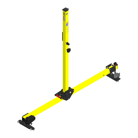
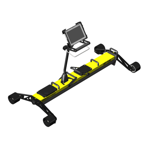
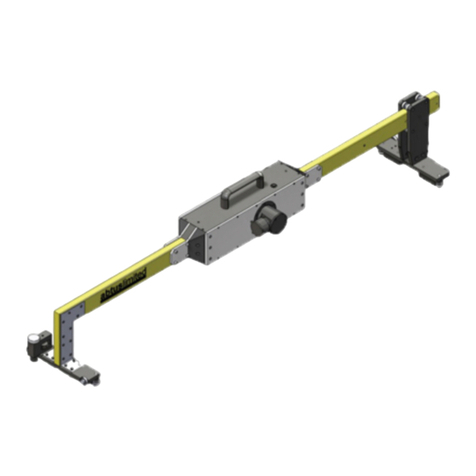
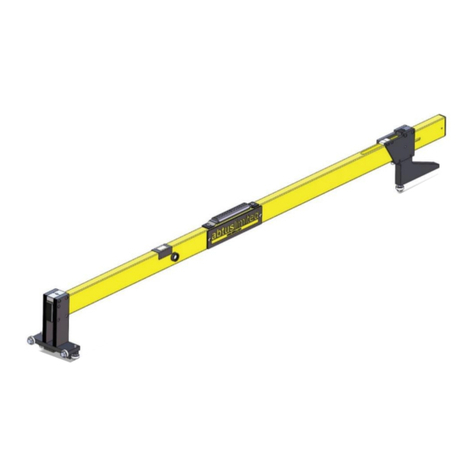
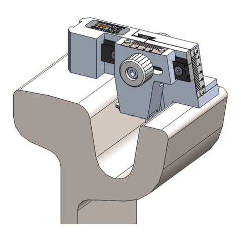
Abtus ABT-7000 User manual

ABT-7000 Abtus Cyclic Top Measurement
Device (CTMD)
Instruction Manual

2
1.0 Index
1.0 Index ................................................................................................................................. 2
2.0 Item List............................................................................................................................. 3
3.0 Specification ...................................................................................................................... 4
4.0 Getting Started................................................................................................................... 5
4.1 Overview ....................................................................................................................... 5
4.2 Assembly....................................................................................................................... 6
5.0 Maintenance .................................................................................................................... 12
5.1 Every 3 Months............................................................................................................ 12
5.2 Annual......................................................................................................................... 12
6.0 Measurement Characteristics ........................................................................................... 12
6.1 Cyclic Top Faults ......................................................................................................... 12
6.2 Gauge ......................................................................................................................... 13
6.3 Super-Elevation........................................................................................................... 13
6.4 Twist ........................................................................................................................... 13
6.5 Distance...................................................................................................................... 14
6.6 GPS ............................................................................................................................ 14
7.0 Transportation and Storage .............................................................................................. 14
8.0 Software Introduction........................................................................................................ 14
8.1 Cyclic Top Measurement Device Software.................................................................... 14
8.2 Initial Setup ................................................................................................................. 14
9.0 Before going on track ....................................................................................................... 15
9.1 Check Battery Levels................................................................................................... 15
9.2 Check Wireless Connection ......................................................................................... 15
9.3 Before Each Use.......................................................................................................... 15
9.4 Training and responsibilities......................................................................................... 16
9.5 Cyclic Top Fault Report from Measurement Train ......................................................... 17
9.6 Tools........................................................................................................................... 17
10.0 Step by Step Guide to Recording Cyclic Top Measurements on Track ............................... 18
11.0 Viewing a Recording......................................................................................................... 24
Step 1: View Cyclic Top Faults for a specific wavelength......................................................... 24
Step 2: Comparing results before and after maintenance......................................................... 25
11.1 PDF Recording Report................................................................................................. 29
12.0 Track Repairs................................................................................................................... 31
12.1 ‘Repair Track’ Screen................................................................................................... 31
12.2 Repair Report PDF ...................................................................................................... 32
13.0 Step by Step Guide to Recording Geometry Measurements on Track ............................ 34
14.0 Troubleshooting ............................................................................................................... 41
15.0 Using the Geode GPS as a stand-alone product................................................................ 42
15.1 When used as part of the CTMD .................................................................................. 42
15.2 To use the Geode GPS as a stand-alone product ......................................................... 42
16.0 Directive and standards.................................................................................................... 43
3
2.0 Item List
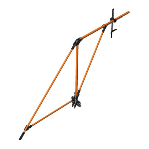
1. CTMD = 1 (Right Side) + 2 (Left Side) + 3 (Handle)
(See assembly section of this manual)
(1) (Left Side) contains: GPS (A), Red LED Lights (B), Gauge Retraction Lever (C)
(2) (Right Side) contains: 2x Removable 12V Lithium Ion Batteries (D), On/Off Power
Button (E) & Locking Lever (F)
2. FZ-G1 Panasonic Tablet + User Manual & Charger
3. FZ-G1 Panasonic Tablet Holder
4. Battery Charger + Accessories
5. CTMD Instruction Manual
6. Transit Cases
3
C
A
1
2
D&E
W
F
B

4
3.0 Specification
Weight
- CTMD on Track
- Bag 1 & Bag 2
- Panasonic Fz-G1 Tablet
- Chargers & Other
- CTMD in Bags
25.9 kg
3 kg ea. (Total 6 kg)
1.1 kg
1 kg & 1 kg
35 kg
Physical Dimensions
- CTMD on Track
- Bag 1
- Bag 2
Length: 1610 mm to 1700 mm
Height: 1000 mm
Width: 720 mm
Length: 870 mm
Height: 300 mm
Width: 790 mm
Length: 1010 mm
Height: 300 mm
Width: 790 mm
Operating Temperature
-
-10°C to + 50°C (-4°F to 122°F)
Environmental Rating
-
IP65 Assembled
Battery Life
- CTMD 2x Lithium Ion
- Panasonic FZ-G1 Tablet
Up to 6 hours per battery
Up to 6 hours
Operating System
-
Windows 64 bit
Trolley Connectivity
-
Wi-Fi

5
4.0 Getting Started
4.1 Overview
The Abtus ABT7000 is a measuring device which records cyclic top geometry while being pushed by
an operator at walking speed.
The device can be assembled by one operator. Since the weight of the trolley weighs 28 kg the trolley
should only be lifted in its entirety if the user feels as though they feel fit to do so, otherwise the trolley
should be disassembled and carried by two operators. The device can be dismantled to fit into two
protective transportation bags.
Cyclic top track geometry data is transmitted from the measuring device via Wi-Fi to a Panasonic FZ-
G1 running a Windows 64 bit operating system supplied with the Cyclic Top Software. The software
displays track geometry data including Distance, Cant/ SE, Twist and Gauge in real time. The Cyclic
Top analysis can be viewed only at the end of a measurement. The data is saved as a .csv file
containing distance, Cant/SE, Twist and Gauge data and as a PDF contains the cyclic top analysis
report. PDF reports can be transferred to other devices via a USB flash drive.
The trolley is intended to be used for the measurement of cyclic top faults and track geometry
measurements.
The CTMD is designed with the following characteristics:
This product is used to accurately record Distance, Cant/SE, Twist, Gauge, Cyclic Top
depth and cycles for railway maintenance.
Non-conducting: The trolley is insulated and therefore does not create electrical contact
between the two running rails. This is achieved by using plastic wheels and also
accommodates a non-conductive insulation block between the wheel arm and contact
bearings.
Lights: The trolley is fitted with red LED lights on the front and back to enable other track
users and train drivers of the operator’s presence on track.
Compact: The CTMD breaks down into 3 separate parts to allow it to fit into most vehicle.
Portability: The CTMD is designed to be easily lifted onto and off the track. This is done
using the plastic lifting handles provided.
The unit has been designed to be user-friendly with only limited training required.

7
Lock the two halves together by pushing the locking lever towards the right until it firmly
snaps into position.
Before attaching the handle, ensure that the locking levers are positioned towards the
plunger on the back of the handle block as shown in Figure 5.
Figure 4 - Locked Position
Figure 5 - Handle Locking Lever
Position
Handle
Rotation
Plunger
Orientation
Indication
Mark

9
To lock the handle into position, rotate the locking levers towards the indication mark.
The CTMD comes with a RAM Mount holder for the Panasonic FZ-G1 as shown in Figure 9,
which is spring loaded for ease of insertion and removal.
Figure 8 - Handle in its Locked Position
Figure 9 - Panasonic FZ-G1 Holder

10
To attach the holder to the CTMD handle, simply insert the two 1” diameter rubber balls into
the short double socket arm cups as shown in Figure 10.
The CTMD has been designed with the user in mind. The trolley has a rotating handle to
prevent the user having to lift and rotate the trolley on track. The handle has three locking
positions and a position has been added to allow the user to push the trolley in the cess or
in areas of limited access. To rotate the handle please see Figure 11.
Figure 10 - Short Double
Socket Arm
Figure 11 - Handle Rotation

11
The CTMD trolley has a retraction lever to allow the user on track to retract the gauge
through switch and crossing. The trolley uses a spring to self-align in the running rails, the
gauge is in its released position when the lever is towards the right as shown in Figure 12.
The gauge is in its retracted position when the lever is towards the left as shown below:
Figure 12 - Fully Extended
Figure 13 - Fully Retracted

12
5.0 Maintenance
The CMTD does not require any lubrication as all the moving parts have sealed or dry running
bearings. However the following routine checks must be carried out on the trolley:
5.1 Every 3 Months
Visually inspect the CTMD for signs of damage. If necessary, contact your distributor for
help.
Check that when the trolley is assembled, there is no play in the central joint.
5.2 Annual
The CTMD must be returned to Abtus Ltd annually for re-calibration to ensure measurements are
within specification. The condition of all components will be checked at this time and replaced as
required. Each trolley should have at least one trained operator who is responsible for returning the
trolley.
The trolley is marked with a calibration sticker inside of the battery compartment showing the next
annual due date and must be returned to Abtus for annual calibration and maintenance. If the trolley
is used beyond the calibration due date the performance may be degraded.
If the equipment becomes defective, or if it has an out of date calibration sticker, a warning notice
should be placed on the device to prevent further use and should be returned to Abtus for repair,
maintenance and re-calibration.
6.0 Measurement Characteristics
6.1 Cyclic Top Faults
Cyclic Top Distance Range
2 - 200m
Cycle Lengths Detected
4.5m, 6m, 9m, 13m, 18m
Depth Range
0-30mm
Depth Accuracy
±2mm
Depth Resolution
0.1mm
The ABT7000 measures top faults which, when present on the track at a regular interval form Cyclic
top.
Top faults are measured by calculating the vertical versine along the length of the track and
identifying the peak values. The identified peaks are reported to the user as cycles and are shown
on the screen as vertical bars of a height equal with the versine measured in millimetres. The chord
length of the versine is selectable by the user between 4.5 m, 6 m, 9 m, 13 m and 18 m and the
measurement is carried out every 0.1 m. The measurements are done without loading the track and

13
thus the results are likely to differ when compared with other measurement methods such as
measurement trains.
Top faults of less than 2 mm in depth are not displayed to the user. Top faults have to exceed 5 mm
in order for the software to treat them as cycles (count them and report them). The reported cycles,
depending on their position along the track, may or may not form a cyclic top fault. The software
does not tell the user whether or not the cycles form a cyclic top fault, but the stars displayed on the
graph can be used as a guide to see if there are three or more cycles in a regular interval.
The software will show any cycles present on the track, even if just one is present (which is not
enough to form a cyclic top fault). Results are likely to differ when compared to other means of
measurement such as the measurement train which reports the cycles only if they form a cyclic top
fault and exceed other types of thresholds.
6.2 Gauge
Note: This measurement is taken from the internal running edges of the tracks at P-point (usually -
14mm) distance from the top of the rail.
Range
-25/+65mm (on nominal)
Accuracy
±1mm
Resolution
0.1mm
6.3 Super-Elevation
Range
±250mm
Accuracy
±1mm
Resolution
0.1mm
Super Elevation (SE) is measured across the running rails and is displayed as height differential
between the high and low rail in millimetres
The default sign convention is: Left rail up is positive Cant/SE
During Cyclic Top measurements the software records the trolley half labelled “L” as being
the left rail. During geometry measurements the left and right side is determined by the
direction of travel.
6.4 Twist
Range
±250mm
Accuracy
±1mm
Resolution
0.1mm

14
Twist is when one rail has a downward gradient while the other rail has an upward gradient,
causing the carriage to twist. Twist is normally calculated over the bogie length (Traditionally 3m)
and the bogie centre to centre distance (Normally 12m).
6.5 Distance
Maximum limit on the number of measurements
per recording for Gauge, SE & Twist
50,000
Recording Increment
0.1, 0.2, 0.25, 0.5 & 1.0 m
Accuracy
±1%
Resolution
10mm
6.6 GPS
Accuracy
±2 m (In sunny clear sky conditions)
The GPS accuracy varies by time and location thus the user should wait 1 –2 minutes to achieve
the best accuracy.
7.0 Transportation and Storage
The CTMD must be transported inside its transportation bags. The bags should be moved by two
people following safe manual handling practices. The bags should be stored flat to prevent them
falling over.
If the trolley is not going to be used for several weeks, it is strongly recommended that the
batteries be fully charged and that the trolley be stored away from direct sunlight in a location of
low humidity where the temperature will be between: +15ºC & +25ºC (68OF to 77OF).
8.0 Software Introduction
8.1 Cyclic Top Measurement Device Software
The Cyclic Top Measurement Device software is installed on the Windows device that comes with
the CTMD. This guide explains the important features of the CTMD software that are necessary
for measuring and analysing cyclic top faults.
8.2 Initial Setup
No initial setup is required as Abtus will install the CTMD software and any necessary wireless
drivers. If the Windows device does not connect to the CTMD contact Abtus for support.

15
9.0 Before going on track
9.1 Check Battery Levels
The CTMD has two removable batteries which are accessed from the lid in the top of the
Measurement Device. Press the battery indicator button to check the charge of the batteries and
charge them if necessary, you can also see the battery voltage in the start a recording screen.
Check the battery levels on the Panasonic FZ-G1 Tablet by clicking on the battery icon bottom right
of the tablet.
9.2 Check Wireless Connection
Switch on the CTMD and ‘Cyclic Top’should appear in the list of wireless networks available and
windows should automatically connect to it. Open the CTMD software on the Windows tablet and
click ‘Connect via Wi-Fi’ to check that the connection is working between the tablet and the trolley.
9.3 Before Each Use
The following checks should be carried out in the office or depot before taking the trolley onto the
track.
The condition of the trolley should be checked by the operator before it is used. The trolley
must be in good condition with no loose or broken components.
The trolley must be marked with a valid calibration sticker showing the next annual due date
located inside of the battery compartment. The trolley should not be used after the
calibration due date.
Figure 14 - CTMD Software Home Screen

16
The batteries should have sufficient charge before the trolley is taken onto track. This is
shown by pressing the battery indicator button on each battery.
The electrical connection pins between the two parts of the device should be clean.
An appropriate and adequate safe system of work must be in place before the trolley is
used.
Ensure that all wheels rotate freely.
Ensure that there is nothing on the wheels. (dried mud, leaves or any other debris)
It is possible around the guide bearing shroud for dirt and grease build up, ensure this is
clear to allow the bearings to run freely.
The trolley is fitted with a dead man brake which can cause flat spots on the wheels if the
brakes are engaged whilst pushing the trolley. Check all wheels for flats or grooves. If any
are found, the trolley must be returned to Abtus as this can result in inaccuracies.
The safety brakes should be functioning correctly. The brakes are applied to two of the
wheels which can be tested by spinning the wheels and releasing the brake lever on the
main handle ensuring that both wheels lock firmly.
9.4 Training and responsibilities
Only trained and competent people should use the trolley.
All users must have received adequate training for the use of the trolley.
A trained person will be responsible for the trolley during the work shift. This includes carrying
out the safety and performance related checks described in the user manual.
Operators should have read the instruction manual for the CTMD and have access to it for
reference.
Operators should understand the accuracy levels of the trolley.
The trained operator is responsible for using the trolley safely in accordance with the safety
guidelines in the ABT7000 HAZOP Safety Risk Assessment and for ensuring that any risks
identified are kept as low as reasonably practical. They are responsible for informing any
other staff of safety requirements relating to the trolley that affect the planning of the work to

17
be carried out. The trained operator should challenge any instruction that compromises safe
use of the equipment and is responsible for communicating the risks involved.
9.5 Cyclic Top Fault Report from Measurement Train
The CTMD is designed to measure track sections which the measuring train has identified as having
cyclic top faults. The CTMD can be used before, during and after maintenance.
The measuring train produces a fault report showing the GPS position, wavelength, number of
cycles of the cyclic top fault and the category of severity on a scale I, A, B, C, and D. The direction
of the measuring train can be identified by checking the mileage data. The GPS position gives the
start of the fault.
9.6 Tools
It is recommended to take spray paint to mark the start & end position of the cyclic top fault so that
recordings done before and after maintenance at the same location.
Figure 15 - Measure Train Fault Report Example

18
10.0 Step by Step Guide to Recording Cyclic Top Measurements
on Track
STEP 1. Put the CTMD on the track
The CTMD should be positioned near to the cyclic top fault with the fixed side (marked L) on the
left rail, facing the direction of travel of the measurement train.
STEP 2. Connect the Windows device to the CTMD
- Turn on the CTMD and the Windows device.
- Open the CTMD software to see the home screen.
- Click ‘Connect to Wi-Fi’ in the top left corner of the screen.
- The trolley begins to send real time data to the Windows device. The Gauge, Cant/SE are
displayed below the ‘Connect to Wi-Fi’ button, but they are not recorded.
Figure 16 - CTMD Software Connecting

19
Step 3: Move to GPS location of Cyclic Top Fault
- Click ‘Start a new recording’ in the bottom left of the screen.
- In the ‘Start a new recording’ pop-up window, input the GPS position of the fault given by the
measurement train into the ‘Fault GPS loc’ text box. The current GPS location is displayed in
‘Current GPS loc’ as well as the distance to the fault.
- Move the CTMD until it is at the GPS position of the cyclic top fault - this is when the ‘Distance to
fault’ box displays less than 1 – 2 m.
- Mark the zero position with spray paint on the nearest sleeper to the GPS position (the spray
paint will allow post maintenance measurements to start from the same position).
- Press ‘Cancel’ to close the pop-up window.
- On the home screen click ‘Set zero position’.
Figure 17 - Starting a New Recording

20
STEP 4. Calculate Measurement Distance & Position CTMD on Track
- Move the trolley backwards to -20m from the start of the Cyclic Top fault. (Double check that the
CTMD has the fixed side (marked L) on the left rail)
- The length of the fault is found on the measuring train fault report. The cyclic top fault has a start
and end position shown in miles and yards. Subtract the start yards from the ending yards and
multiply the difference by 0.91 to give the length of the fault in metres.
For example, for the below mileage:
074.0556 (25)
074.0489 (22)
The length of the fault in yards is 556-489=67 yards and thus in meters 60.97 m.
The end of the measurement is at the length of the fault + 20 m thus in this example is 80.97 m.
STEP 5. Record a Cyclic Top Fault
- Press ‘Start new recording’.
- Input the Operator name.
- Input the Filename.
- Click ‘Start recording’ and leave the trolley in a static position. (The software will guide the user on
the necessary waiting time)
Figure 18 - Calculate Distance to Measure Diagram
Table of contents
Other Abtus Measuring Instrument manuals

Abtus
Abtus ABT-7100 User manual

Abtus
Abtus ABT5210 Ri59 User manual

Abtus
Abtus ABT4650 RouteScan User manual

Abtus
Abtus ABT 8000 User manual

Abtus
Abtus IFP-600 User manual

Abtus
Abtus ABT4050 User manual

Abtus
Abtus ABT4650 RouteScan User manual

Abtus
Abtus ABT4640 User manual

Abtus
Abtus ABT 4550 Series User manual

Abtus
Abtus ABT5200 User manual
Popular Measuring Instrument manuals by other brands

Diehl Metering
Diehl Metering HYDRUS 171A installation guide

ddtop
ddtop UFM Operation manual

Teledyne Lecroy
Teledyne Lecroy PCI Express Gen 4x8 OCuLink user manual

Xylem
Xylem FLYGT Concertor APP 411 Installation, operation and maintenance manual

IS Technologies
IS Technologies SLM800S user manual

HEDÜ
HEDÜ L223 Operator's manual