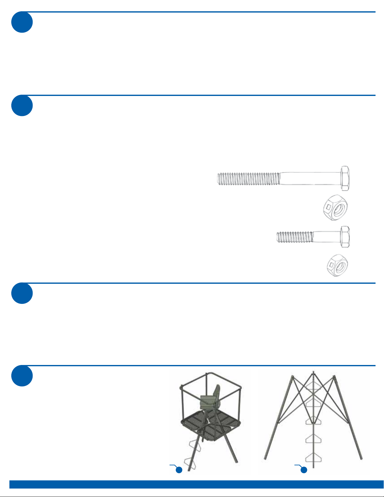
ACADEMY Summit Classic Deluxe Tripod 12 Leg Kit User manual

Summit Classic
Deluxe Tripod 12’ Leg Kit
PN 81519
WARNING
!
You must fully read, understand and follow these warnings
and instructions (written and video)! Failure to follow these
instructions may cause serious injury or death!!
You MUST also view the enclosed DVD BEFORE using your new treestand!!
WEIGHT LIMIT
SINGLE USER
300 LBS. X 1 TOTAL*
DO NOT EXCEED THIS LIMIT!
(* Includes all gear)
• IT IS IMPORTANT TO NOTE THAT A FALL CAN OCCUR AT ANY TIME AFTER LEAVING THE GROUND.
• ALWAYS MAINTAIN THREE POINTS OF CONTACT WHEN YOU CLIMB THE LADDER SECTION OF THIS TRIPOD!
• READ AND UNDERSTAND ALL OF THE MANUFACTURER’S WARNINGS AND INSTRUCTIONS AND USE ALL SAFETY DEVICES PROVIDED.
CONTACT SUMMIT TREESTANDS FOR ANY QUESTIONS. FAILURE TO DO SO COULD RESULT IN INJURY OR DEATH!
• A SIGNAL DEVICE SUCH A MOBILE PHONE, RADIO, WHISTLE, SIGNAL FLARE OR PERSONAL LOCATOR DEVICE (PLD) MUST BE ON YOUR
PERSON AND READILY AVAILABLE AT ALL TIMES! ALWAYS INFORM SOMEONE OF YOUR HUNTING LOCATION, WHERE THE TRIPOD WILL
BE LOCATED AND THE EXPECTED DURATION OF THE HUNT!
• DO NOT USE THIS TRIPOD UNLESS YOU ARE IN GOOD PHYSICAL SHAPE AND HAVE NO PHYSICAL LIMITATIONS OR MEDICAL CONDITIONS
WHICH MAY PREVENT YOU FROM SAFELY USING THIS PRODUCT. ALWAYS CONSULT A PHYSICIAN IF YOU HAVE ANY QUESTIONS ABOUT
YOUR PHYSICAL ABILITY TO USE THIS PRODUCT.
• NEVER USE THIS TRIPOD WHILE TAKING DRUGS, ALCOHOL OR CERTAIN PRESCRIPTION DRUGS! ALWAYS CONSULT A PHYSICIAN IF YOU
HAVE ANY QUESTION ABOUT TAKING SPECIFIC MEDICATIONS AND USING THIS PRODUCT!
• NEVER USE THIS TRIPOD DURING INCLEMENT WEATHER SUCH AS RAIN, LIGHTNING, WINDSTORMS OR ICY CONDITIONS! END YOUR
HUNT AND RETURN TO THE GROUND IF ANY OF THESE INCLEMENT CONDITIONS ARISE.
• NEVER USE THIS TRIPOD WHEN FEELING ILL, NAUSEOUS, DROWSY OR DIZZY!
• BE WELL RESTED AND NEVER HURRY. HURRYING CAUSES ACCIDENTS!
• CHECK EVERY COLUMN SECTION CONNECTION EVERY TIME YOU USE THE TRIPOD. IF ANY COLUMN SECTIONS ARE SEPARATING - DO
NOT USE THE TRIPOD!
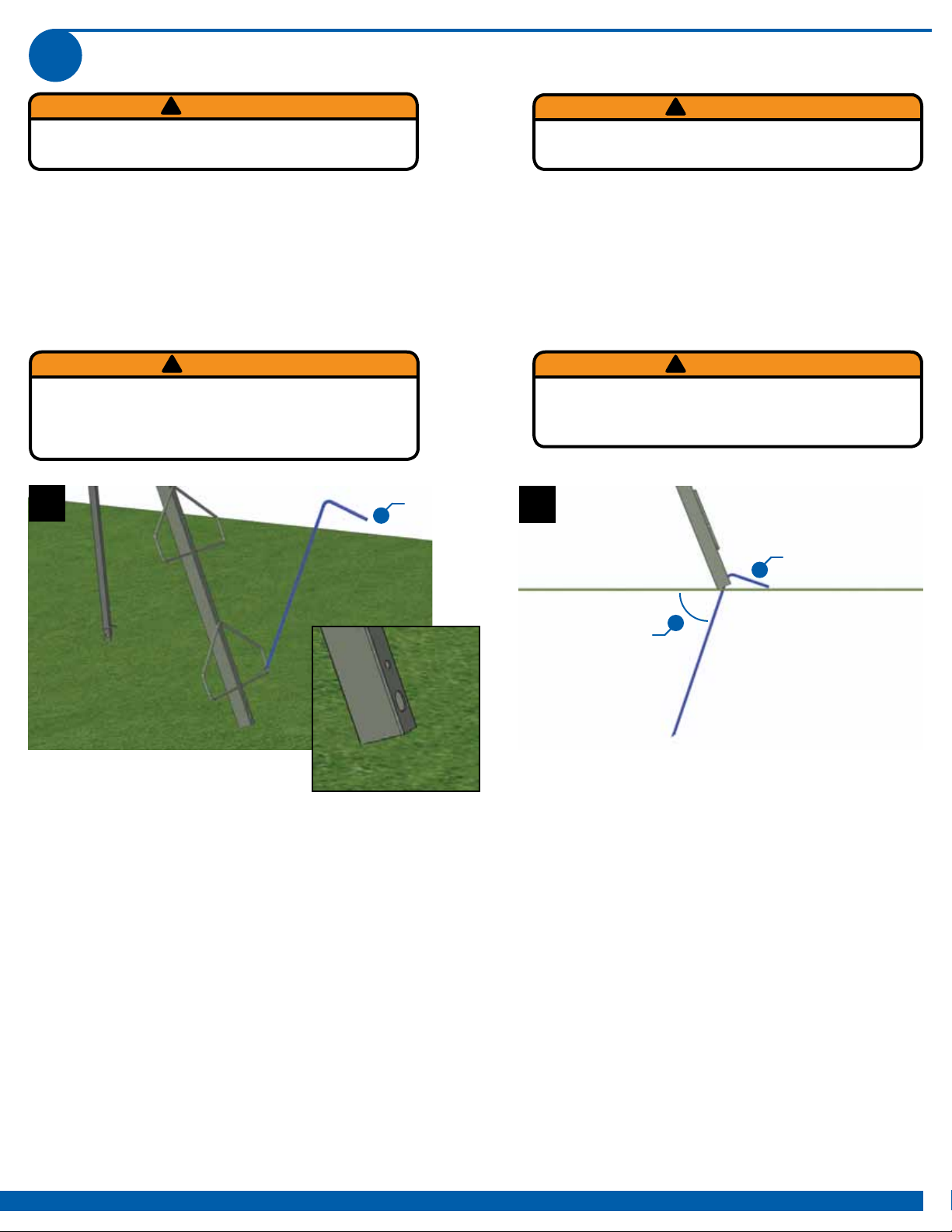
• ALWAYS USE THE SUPPLIED SPIKES TO SECURE THIS TRIPOD TO THE GROUND BEFORE USE - EVEN IF IT IS TO BE USED WITHOUT A LEG
EXTENSION KIT!
• NEVER SETUP OR USE THIS TRIPOD AROUND POWER LINES, POWER TRANSFORMERS, SUBSTATIONS OR POWER GENERATORS!
• CHECK THE GROUND UNDER THE TRIPOD TO MAKE SURE IT IS FIRM AND LEVEL. SLOPING GROUND OR AN UNEVEN SURFACE (ONE
COLUMN SECTION ON A ROCK FOR EXAMPLE) CAN CAUSE YOUR TRIPOD TO TILT OR SHIFT AS YOU CLIMB.
• PULL UP A BOW, BACKPACK, FIREARM OR OTHER EQUIPMENT ONLY AFTER BEING SECURE IN THE TRIPOD. FIREARMS MUST BE PULLED
UP UNLOADED, CHAMBER OPEN AND MUZZLE DOWN!
• NEVER MODIFY YOUR TRIPOD IN ANY WAY BY MAKING REPAIRS, REPLACING PARTS, OR ALTERING ADDING OR ATTACHING ANYTHING
TO IT EXCEPT IF EXPLICITLY AUTHORIZED IN WRITING BY THE MANUFACTURER!
• INSTRUCTIONS (WRITTEN AND VIDEO) SHOULD BE KEPT IN A SAFE PLACE AND REVIEWED AT LEAST ANNUALLY. IT IS THE RESPONSIBILITY
OF THE TRIPOD OWNER TO FURNISH THE COMPLETE INSTRUCTIONS TO ANY PERSON WHO BORROWS OR PURCHASES THE TRIPOD! THIS
SUMMIT TRIPOD IS DESIGNED TO BE USED AS A COMPLETE SYSTEM - NEVER LOAN OR SELL ONLY A PORTION OF THIS TRIPOD.
• BEFORE EACH USE OF YOUR SUMMIT TRIPOD, ALWAYS INSPECT THE TRIPOD FOR ANY DAMAGE, CRACKS, TEARS, WEAR OR ABRASION
THAT MAY HAVE OCCURRED IN TRANSPORTING / STORING YOUR TREESTAND. DO NOT USE IF ANY DAMAGE IS FOUND! CONTACT
CUSTOMER SERVICE FOR THE APPROPRIATE REPAIR / REPLACEMENT PROCEDURE!
• DO NOT LEAVE YOUR TRIPOD OUTDOORS WHEN IT IS NOT BEING USED! ANY STAND TUBING THAT IS ALLOWED TO FILL WITH
RAINWATER AND FREEZE WILL RUPTURE OR BURST - DO NOT USE YOUR TRIPOD IF THIS OCCURS!
• ALWAYS USE FOUR PEOPLE TO SETUP THIS TRIPOD!
2010 Academy Series Tripod 12’ - 2/2010
WARNING
!
This 12’ Leg Kit MUST ONLY BE USED with the Summit Classic Deluxe Tripod Top, PN 81518.
DO NOT USE this leg kit with any other model of Tripod, Ladder or Treestand.

1 INDEX
PG 2
GENERAL WARNINGS AND PRECAUTIONS, TRIPOD WEIGHT LIMITS PG 1
SECTION 1 - INDEX PG 2
SECTION 2 - PARTS LIST PG 2
SECTION 3 - TOOLS REQUIRED PG 2
SECTION 4 - ASSEMBLY PG 3 - 6
SECTION 5 - SETUP AND USE PG 7
SECTION 6 - MAINTENANCE AND CARE PG 8
SECTION 7 - LIMITED WARRANTY INFORMATION PG 8
2 PARTS LIST
BOX CONTENTS
PN DESCRIPTION QTY
14061.300 COUPLER PLATE 3
14061.400 BRACKET 6
14061.500 CROSS BRACE 6
14063.1100 12’ LADDER ASSEMBLY 1
14063.1200 12’ LEG ASSEMBLY 2
14063.1300 HARDWARE PACKET 1
14060.1601 INSTRUCTION BOOKLET 1
14060.1700 INSTRUCTIONAL DVD 1
4ASSEMBLY
3 TOOLS REQUIRED
Please call 256-353-0634 or visit http://www.summitstands.com/contactus/
if you have any questions, if you need replacement parts, if you have any missing parts or if the
included DVD does not play.
www.summitstands.com
Tools Use
• 7/16” Wrenches and / or Socket / Ratchet Leg Braces - 1/4x20 hardware
• 1/2” Wrenches and / or Socket / Ratchet Leg Couplers / Brackets - 5/16x18 hardware
- Assembly can be made easier by the use of a powered ratchet or drill with socket adapter (take care not to overtighten
when using power tools to assemble)
- It is recommended that all bolts be sorted by thread count / length prior to assembly.
- Due to the large size of these tripods, it is mandatory that three people initially setup the tripod.
14063.1300- HARDWARE PACKET
Throughout these instructions, bolts listed in RED are
5/16” thread. Bolts listed in BLUE are 1/4” thread.
PN DESCRIPTION QTY
10610 2 3/4” BOLT, 5/16x18 9
10617 LOCK NUT, 5/16x18 9
10600 1 1/2” BOLT, 1/4x20 12
10612 LOCK NUT, 1/4x20 12
COMBINING WITH PN 81518
1. Please refer to the written instructions
included with your Summit Deluxe Tripod
Top for information on how to assemble
the top section.
2. The completed 81518 top can be
transported as a unit to make assembly
easier in the field.
PN 81518 PN 81519

PG 3
LEG ASSEMBLY
1. Carefully lay the completed 81518 top section on its side
- ladder rungs up as shown in figure 1.
2. Position one of the Couple Plates as shown in figure 2.
Slide the plate over the leg and line up the holes. NOTE:
Coupler Plate must line up with the round holes and not the
oval holes.
3. Position one of the Brackets as shown in figure 3. The
bracket should be bolted to the Coupler Plate so that it runs
horizontal when the tripod is sitting upright.
4. Use one 2 3/4” bolt and lock nut to secure both the
Bracket and Coupler Plate.
1
COUPLER PLATE
(PN 14061.300)
22 3/4” BOLT, LOCK NUT -
WRENCH TIGHTEN
BRACKET
(PN 14061.400)
3
5. Position the 12’ Ladder Assembly as shown in figure 4.
6. Slide the Assembly into the Coupler Plate and secure
with one, 2 3/4” bolt and lock nut. (see figure 5)
4
12’ LADDER
ASSEMBLY
(PN 14063.1100)
2 3/4” BOLT, LOCK NUT -
WRENCH TIGHTEN
5
7. Carefully rotate the tripod assembly to gain access to one
of the legs.
8. Slide another Coupler Plate on the Leg and line up the
round holes as shown in figure 6.
9. Position one Bracket as shown in figure 6 and secure
using one 2 3/4” bolt and lock nut.
COUPLER PLATE
(PN 14061.300)
BRACKET
(PN 14061.400)
2 3/4” BOLT, LOCK NUT -
WRENCH TIGHTEN
6

PG 4 www.summitstands.com
LEG ASSEMBLY (continued)
10. Position one of the 12’ Leg Assemblies as shown in
figure 6. The oval pre-punched holes MUST be on the far
end of the Leg Assembly. These holes are for the Spikes
included with the 81518 Top Section.
11. Slide the Leg Assembly into the Coupler Plate and
secure using one 2 3/4” bolt and lock nut as shown in figure
7.
12. Rotate the tripod and repeat for the other Leg
Assembly.
2 3/4” BOLT, LOCK NUT -
WRENCH TIGHTEN
7
LEG BRACES
1. Locate the pre-punched hole half-way down the Leg
Assembly.
2. Position one Bracket over this hole from the inside and
secure using one 2 3/4” bolt and lock nut as shown in figure
8. As before, the Bracket should run horizontal to the
ground when the tripod is standing up - You must run this
bolt from the inside out so that the head of the bolt is
sitting on the Bracket when tight.
3. Repeat for the other Leg Assembly and the Ladder
Assembly as shown in figure 9. Use one 2 3/4” bolt and lock
nut to secure each Bracket. You must run these bolts from
the inside out so that the head of the bolt is sitting on
the Bracket when tight.
2 3/4” BOLTS, LOCK NUTS -
WRENCH TIGHTEN
9
BRACKET
(PN 14061.400)
BRACKET
(PN 14061.400)
12’ LEG
ASSEMBLY
(PN 14063.1200)
6
Oval hole must be
on far end of leg
assembly
2 3/4” BOLT, LOCK NUT -
WRENCH TIGHTEN
BRACKET
(PN 14061.400)
8

PG 5
LEG BRACES (continued)
4. The six Cross Braces will attach next. Start by positioning
one Cross Brace as shown in figure 10. This Brace will bolt
to the OUTSIDE of the two Brackets, as shown in figure 11
and figure 12.
5. Use one 1 1/2” bolt and lock nut at each Bracket to
secure the Brace. Run these bolts from the inside out so
that the nut is on the outside of the tube.
CROSS
BRACE
(PN 14061.500)
10
1 1/2” BOLT, LOCK NUT -
WRENCH TIGHTEN
11 12
LEG BRACES (continued)
6. Position one Cross Brace (in blue) as shown in figure
13. This Brace will bolt to the INSIDE of the two Brackets,
as shown in figure 14 and figure 15 and it will sit on the
INSIDE of the Brace installed in Step 4-5 (shown in green)
7. Use one 1 1/2” bolt and lock nut at each Bracket to
secure the Brace. Run these bolts from the inside out so
that the nut is on the outside of the Bracket.
1 1/2” BOLT, LOCK NUT -
WRENCH TIGHTEN
14 15
CROSS
BRACE
(PN 14061.500)
13
Table of contents