ACADEMY LCFF 1.2 Instruction manual

LCFF Setup & Calibraon
Workshop Manual

LCFF 1.2

Contents
1 — Introducon
1 — Important Calibraon Note
2 — Crate Contents
SETUP
3 — LCFF 1.2 General Assembly
4 — Measurement System
5 — Carriage Datums & Clamping
6 — Head Tube & Rear Axle X Seng
7 — Angle Measurement Using Digital Angle Gauge
8 — Head Tube Y Seng
9 — Rear Axle Height Seng - BB DROP
10 — Rear Axle Height Seng - BB RISE
CALIBRATION
11 — Laser Pointer Calibraon
12 — Degrees of Freedom
13 — Correct Grub Screw Adjutment
14 — Calibraon Step 1 - Seat Tube Centre Line
15 — Calibraon Step 2 - Head Tube Centre Line & Roll
16 — Calibraon Step 3 - Rear Axle Centre Line & Roll
17 — Calibraon Step 4 - Rear Axle Yaw
BUILD
18 — Head Tube Pucks & Adaptors
19 — Boom Bracket Adapters & Dummy Axle Setup

LCFF 1.2 Setup & Calibraon
workshop manual v2
Page 1
© The Bicycle Academy Limited 2019
Introducon
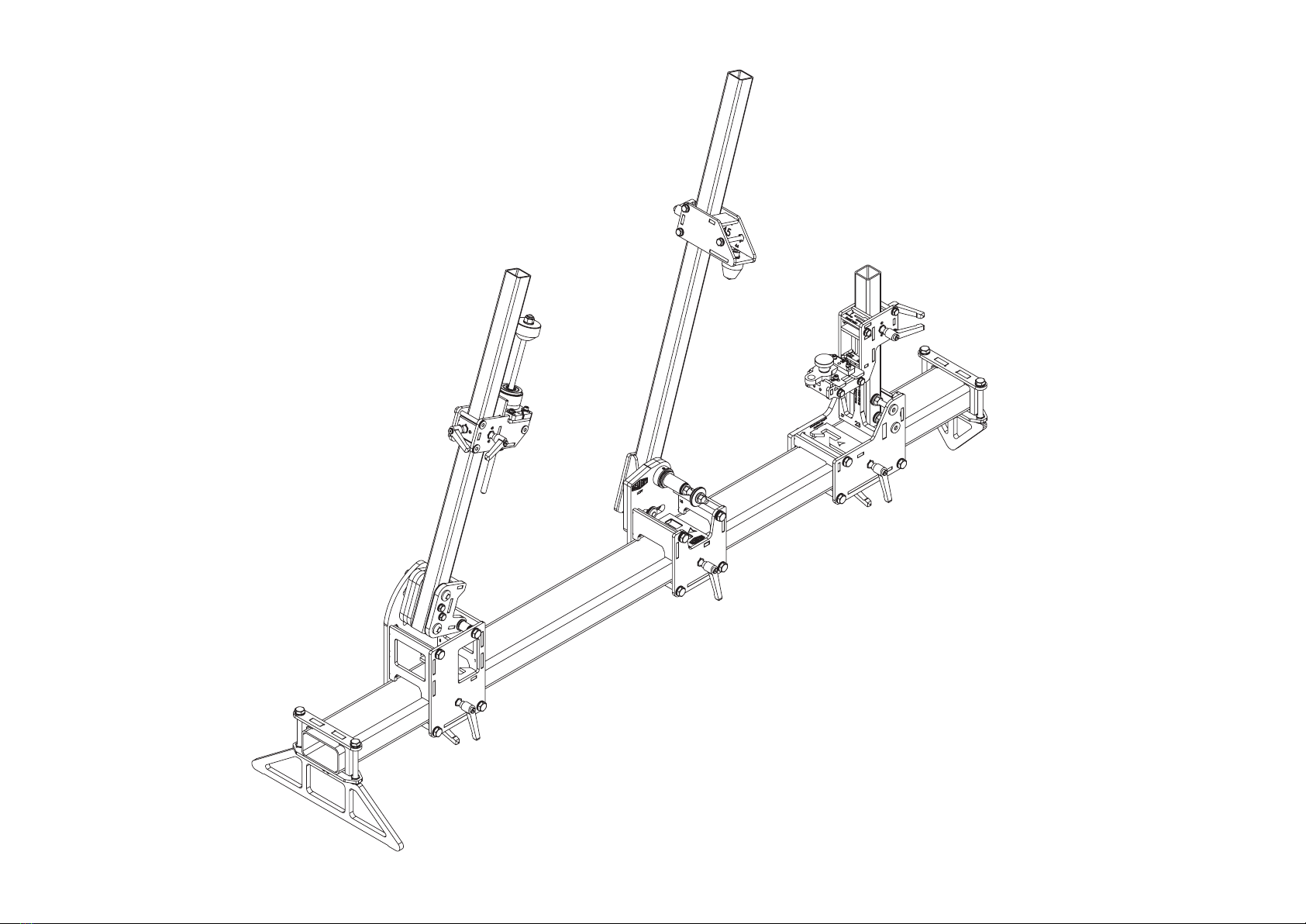
The Academy Tools Low Cost Frame Fixture (LCFF) provides aordability, accuracy
and ease of use thanks to clever design.
Our proprietary User Calibratable Fixture Alignment System gives you the funconality
you need to check and control the alignment of your frame xture, independently at
every interface, every me.
This has opened up some really excing possibilies such as reduced
manufacturing and producon cost, at-pack design, reduced shipping footprint
and cost, user assembly & calibraon and a huge and expandable build range.
As a result the LCFF is the only fully funconal low cost frame building xture in
existence.
Laser Hazard
USE APROPRIATE EYE PROTECTION.
DO NOT LOOK INTO THE DIRECT OR REFLECTED BEAM.
NEVER POINT ANY LASER TOWARDS AIRCRAFT OR
VEHICLES; IT IS UNSAFE AND ILLEGAL.
THIS IS NOT A TOY.
Technical Documentaon
1. Setup & Calibraon Workshop Manual (included with your xture)
2. Assembly Instrucons (download)
PDF versions of both documents can be downloaded here:
hps://thebicycleacademy.org/pages/lc-owners-manual
Hollow Secon Beams
The LCFF is designed to use globally available mild steel hollow secon beams, of a
range of sizes, manufactured to BS EN 10219 or ASTM A500.
These beams are commonly referred to as Rectangular Hollow Secon (RHS) and
Square Hollow Secon (SHS).
Square - 38.1 mm (1.5”) to 40 mm
Rectangular - 100 mm to 101.6 (4”) x 50.8 (2”) to 60 mm
Wall Thickness - 3 mm (0.125”) (reccomended)
See the assembly manual for full details, including secon dimensions and lengths.
Mild steel hollow secon beams are inherently not straight. Each length of beam
will have a degree of bend and twist, within dened limits, this is a natural variaon
resulng from the beam manufacturing process. The Fixture Alignment System has
been designed to accommodate these variaons for the typical range of bicycle
frame sizes.
Setup & calibraon process summary
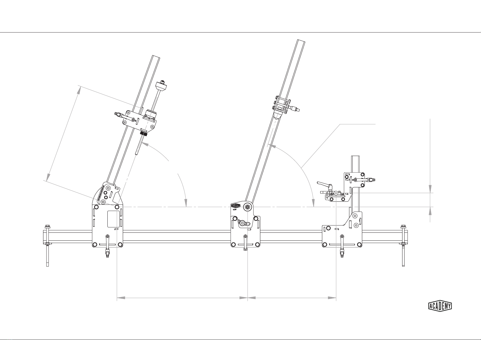
1. Set up the xture to the desired bike geometry (p 3-9)
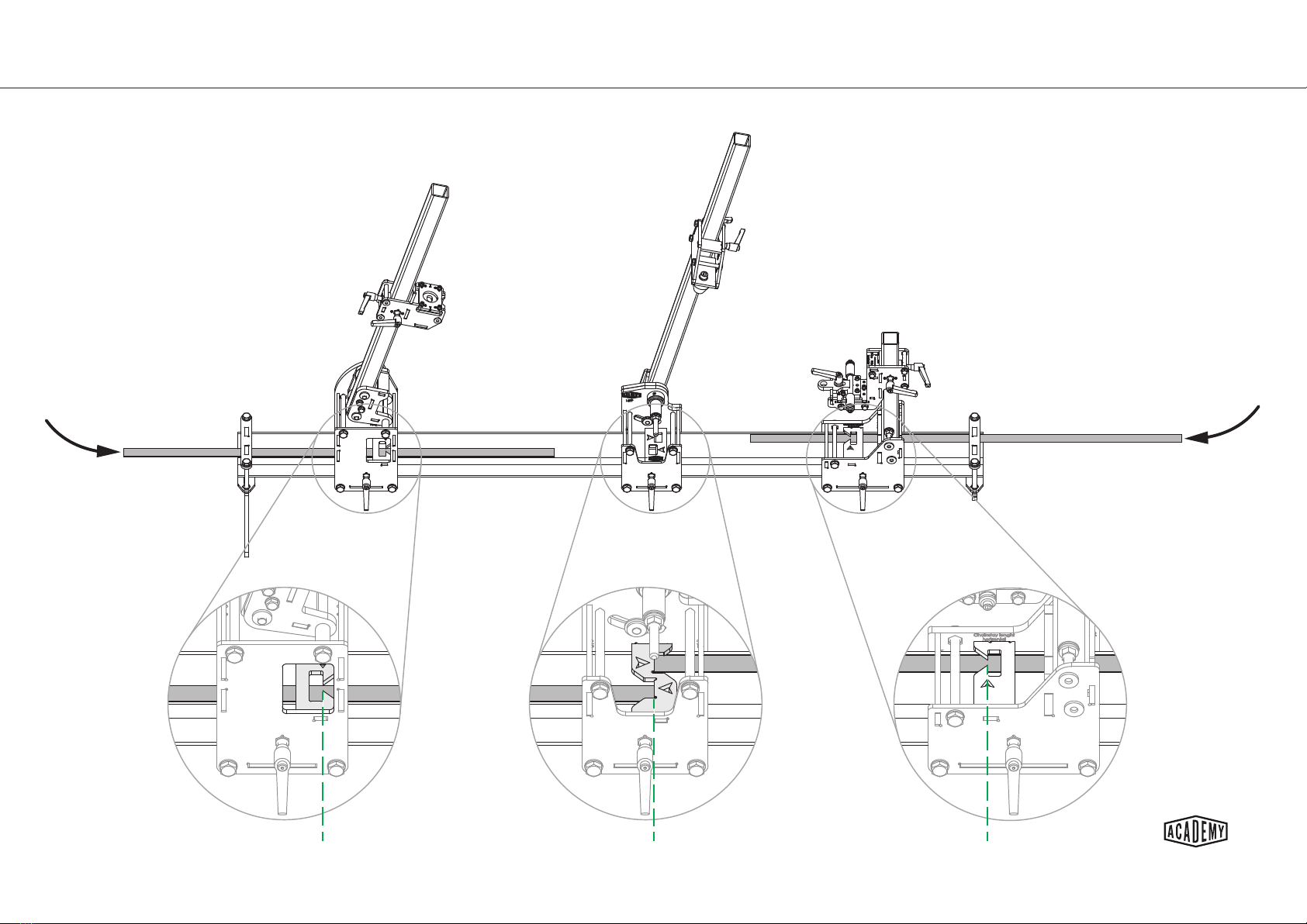
2. Take care to correctly ghten the carriages (p 5)
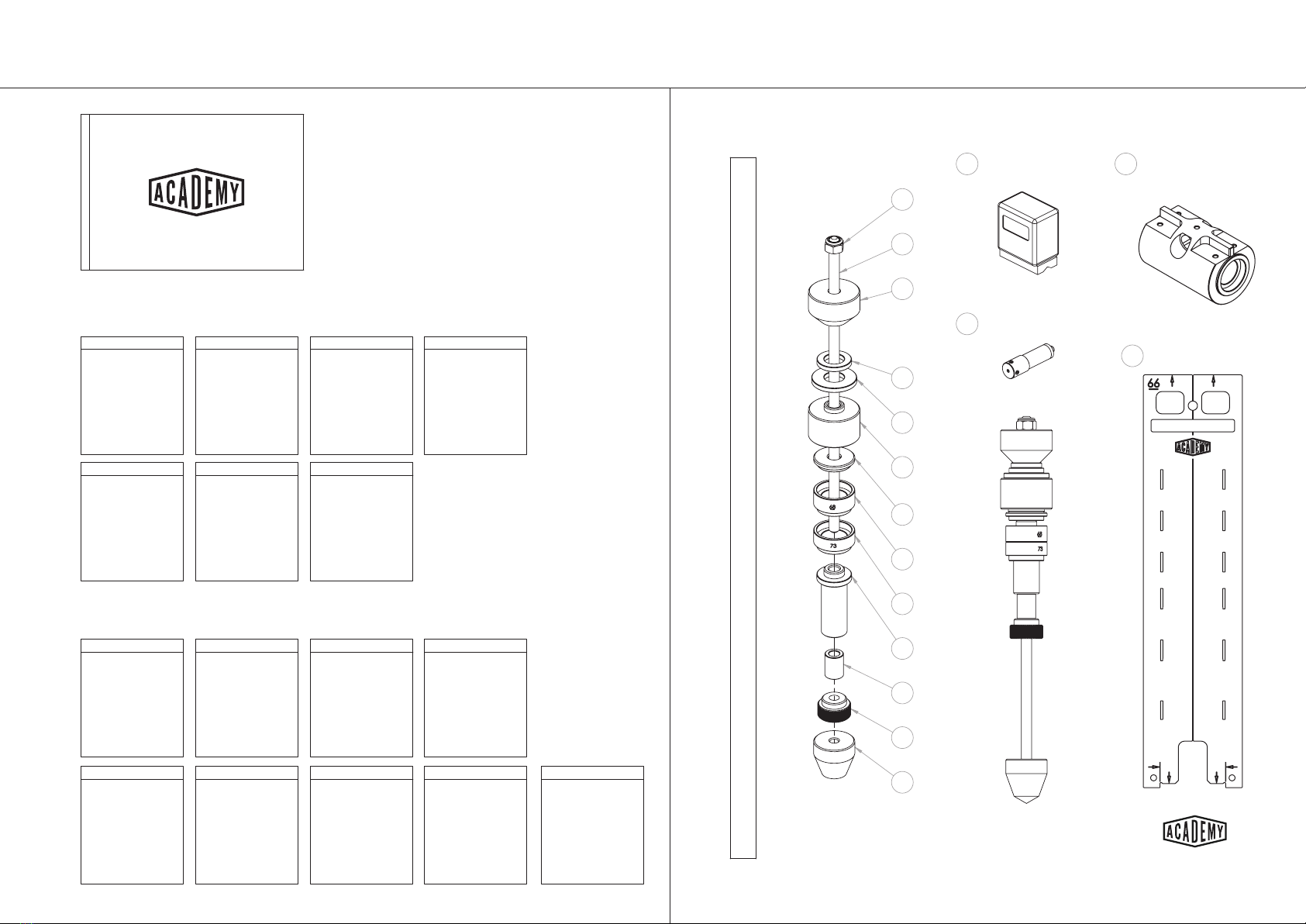
3. Calibrate the laser pointer in the laser holder (p 11)
4. Calibrate the Seat Tube, Head Tube and Rear Axle features (p 12-17)
5. Install the correct bb spacer, head tube adaptor and dummy axle (p 18-19)
Important Calibraon Note
Due to the variaons in the beams it is necessary to calibrate the xture for
each frame geometry setup and every me a carriage is reposioned.
Calibraon of the laser pointer in the laser holder is an essenal rst step
before calibrang the xture.

LCFF 1.2 - Crate Contents
LCFF 1.2 Setup & Calibraon
workshop manual v1
Page 2
© The Bicycle Academy Limited 2019
Fasteners & Fixings packs
Laser cut part
packs
Pack A
Fasteners & Fixings
Main Beam Assembly
Pack B
Fasteners & Fixings
Front Axle Carriage Assembly
Pack C
Fasteners & Fixings
Pack D
Fasteners & Fixings
Rear Axle Carriage Assembly
Pack E
Fasteners & Fixings
Head tube carriage Assembly
Pack F
Fasteners & Fixings
Seat tube carriage Assembly
Pack G
Fasteners & Fixings
Pack H
Fasteners & Fixings
Levers
Laser Pointer
Digital Angle Finder
Pack A
Laser cut parts
Main Beam Assembly
Pack B
Laser cut parts
Front Axle Carriage Assembly
Pack C
Laser cut parts
Pack D
Laser cut parts
Rear Axle Carriage Assembly
Pack E
Laser cut parts
Head tube carriage Assembly
Pack F
Laser cut parts
Seat tube carriage Assembly
Pack G
Laser cut parts
Workshop Manual
BB laser holder
Find fasteners inside
Turned parts
skewer
1m steel rule
222
223
106
111
110
104
103
101
102
100
113
225
107
402
401
66
114
Loose Items

LCFF 1.2 - General Assembly
LCFF 1.2 Setup & Calibraon
workshop manual v1
Page 3
© The Bicycle Academy Limited 2019
LCFF 1.2 Setup & Calibraon
workshop manual v1
Page 3
© The Bicycle Academy Limited 2019
E
F
D
G
C
B
A
402400 66
H
Chain Stay length
Horizontal
LCFF
Head Tube X
LCFF Head Tube Y
Seat angle
Head angle
Bottom Bracket
Drop/Rise
1730
400
LCFF No.
Description
QTY.
Pack
A
Main Beam Assembly
1
A
B
Front Axle Carriage Assembly
1
B
C
1
C
D
Rear Axle Carriage Assembly
1
D
E
Head Tube Carriage Assembly
1
E
F
Seat Tube Carriage Assembly
1
F
G
1
G
H
3
H
66
1
400
Steel ruler 25 mm wide
1
402
4

LCFF 1.2 Setup & Calibraon
workshop manual v2
Page 4
© The Bicycle Academy Limited 2019
Measurement System
Chain Stay length
Horizontal
BB axis to
Steering axis intersect
LCFF Head Tube X
Horizontal
(Henry James X in BikeCAD)
LCFF Head tube bottom
from BB horizontal plane
along steering axis
(Henry James Y in BikeCAD)
Seat angle
Head angle
Bottom Bracket
Drop/Rise

LCFF 1.2 Setup & Calibraon
workshop manual v2
Page 5
© The Bicycle Academy Limited 2019
Carriage Datums & Clamping
Carriage Datums Clamping Order
When securing the carriages, the order and torque applied to the lever or bolt can have a
signicant impact on whether the carriage correctly references the datum faces of the
beam.
For each carriage, the rst clamping lever (or bolt) should be ghtened just enough so
that the carriage is pulled up against the corresponding datum face.
The second lever should then be ghtened so that the carriage pulls up against the second
datum face and also locks the carriage in place.
If the rst lever (or bolt) is overghtened, the carriage up will not be able to move to
reference the second datum face.
Each carriage references two datum faces as highlighted in green.
When reposioning and securing the carriages it is important to ensure
that they are referencing the datum faces correctly.
1
2
1
2
1
Socket head bolt
under carriage
2
1
2
1
2
1
2
1
2
1
2
1
Socket head bolt
under carriage
2
1
2
1
2
1
2

LCFF 1.2 Setup & Calibraon
workshop manual v2
Page 6
© The Bicycle Academy Limited 2019
Head Tube & Rear Axle X Seng
Front axle X reading Bottom bracket ruler datum
Shown without cover plate for clarity
Chainstay length horizontal reading

LCFF 1.2 Setup & Calibraon
workshop manual v2
Page 7
© The Bicycle Academy Limited 2019
Angle Measurement Using Digital Angle Gauge
Head tube Seat tube
Head tube beam
Alternative position for angle finder
when fixture is mounted in LCFF stand
Seat tube beam
Posion the angle nder as shown, so that it references the
main beam and BB carriage datum faces highlighted in green.
Ensure there is no debris on the beam and on the magnec
v-base of the angle nder.
Zero the readout.
Transfer the angle nder to the head tube or seat tube beam as required.
Do not ip the device 180 degrees (note the readout window is facing the same way as when
it was set to zero)
Ensure the front face of the angle nder is sll parallel to the main beam side datum to take
the reading.
To ensure the accuracy of the setup (and head tube roll calibraon) load a head tube and
seat tube into the xture and check the angles again by posioning the angle nder on these
tubes accordingly.
1.
2.
3.
4.
5.
6.
7.

LCFF 1.2 Setup & Calibraon
workshop manual v2
Page 8
© The Bicycle Academy Limited 2019
Head Tube Y Seng
H
e
a
d t
ub
e
Y
r
ea
d
i
ng
Hdatum
e
a
d t
ub
e
Y
Insert the steel ruler as shown.
Push the ruler against the back plate if
necessary to reduce parallax.
Ensure the steel ruler references the
datum plate as shown.
If necessary push the ruler back
against the back plate, in the direcon
of the laser cut arrow.

LCFF 1.2 Setup & Calibraon
workshop manual v2
Page 9
© The Bicycle Academy Limited 2019
Rear Axle Height Seng - BB DROP
BB drop reading
BB drop datum
Insert the steel ruler through
BB drop slot as shown.
Ensure the steel ruler references
the datum plate as shown.

LCFF 1.2 Setup & Calibraon
workshop manual v2
Page 10
© The Bicycle Academy Limited 2019
Rear Axle Height Seng - BB RISE
BB rise reading
BB rise datum
Insert steel ruler
through the BB rise slot
as shown
Ensure the ruler
references the datum
plate as shown

LCFF 1.2 Setup & Calibraon
workshop manual v2
Page 11
© The Bicycle Academy Limited 2019
Laser Pointer Calibraon -
401 114 103 215 221
234
Detail A
Adjustment
grub screw
Set screw
A
Fig. 1
A
Fig. 2
A B
Fig. 3
A C B
Fig. 4
A C B
Fig. 5
Laser pointer calibra�on schema�cs
Direc�on and extent of ini�al error will vary
Masking tape
No BB spacer
Install the laser pointer into the BB laser holder
with one adjustment grub screw aligned horizontally as
shown in detail A and secure in place with the top set
screw.
Posion and secure the head tube carriage as far away
from the BB carriage as possible. Apply some masking tape
to the head tube carriage as shown.
(Fig. 1) - Turn the laser on and posion the laser holder
so that the laser dot strikes the masking tape. Clamp the
laser holder in place with the nut and mark a vercal line
through the centre of the dot (A). Turn the laser o.
(Fig. 2) - Without removing the laser from the holder, or
making any adjustment to the grub screws; re-orientate
the BB laser holder as shown. Switch the laser on and
adjust the rotaon of the holder so that the laser strikes
the masking tape at roughly the same elevaon as the rst
mark.
(Fig. 3) - Mark another vercal line where the laser strikes
the tape (B). It is important that the head tube carriage has
not moved since making the rst mark.
(Fig. 4) - Measure the distance between the marks and
make another vercal mark half way between (C).
(Fig. 5) - Adjust the horizontal grub screw on the pointer so
that the laser strikes the central mark.
Return the BB laser holder to its original orientaon and
repeat the process so that you are sased that the laser
strikes in the same place with the holder in both orienta-
ons.
This ESSENTIAL process veries that
the laser is projecng perpendicular
to the BB axis.
1.
2.
3.
4.
5.
6.
7.
8.
This ESSENTIAL process validates that the laser
is projecng perpendicular to the BB axis
Ensure the laser holder is securely
clamped with a consistent force each
me a measurement is taken.

LCFF 1.2 Setup & Calibraon
workshop manual v2
Page 12
© The Bicycle Academy Limited 2019
Degrees of freedom that enable xture calibraon
Head tube centre line & roll
Roll
Roll
Yaw
CL
CL
CL
Rear axle centre line, roll & yaw Seat tube centre line

LCFF 1.2 Setup & Calibraon
workshop manual v2
Page 13
© The Bicycle Academy Limited 2019
Correct Grub Screw Adjutment (applicable on head tube carriage & rear axle vercal carriage)
Correct adjustment - grub screws adjusted equally on each side Incorrect adjustment - grub screws adjusted unequally
Ensure that any roll adjustment maintains the 90° relaonship between the
reference plate and the beam.
In the case shown below, there would be a discrepancy in Head tube X
dimension and top tube length.
90°
90°
90°

LCFF 1.2 Setup & Calibraon
workshop manual v2
Page 14
© The Bicycle Academy Limited 2019
Calibraon Step 1 - Seat Tube Centre Line
Set the xture seat angle and cone height for the planned frame build.
Having calibrated the laser pointer (see page 11) aim the laser at the p of the seat
cone and secure the laser holder with a nut.
Slacken the seat cone using the hexagon socket head bolt and slide the cone unl the
laser strikes the very p. This posion will be highlighted by an even light scaer on
the cone.
1.
2.
3.

LCFF 1.2 Setup & Calibraon
workshop manual v2
Page 15
© The Bicycle Academy Limited 2019
Adjustment screws
Adjustment screws
Clamping bolts
Clamping bolts
Calibraon Step 2 - Head Tube Centre Line & Roll
Set the xture head tube X, Y and angle for the
planned frame build.
Insert the laser calibraon tool as shown and ensure it
is referencing the head tube plate correctly.
Having calibrated the laser pointer (see page 11) aim
the laser at the lowest point on the calibraon tool
and secure the laser holder with a nut.
Slacken the 4x M5 clamping bolts to allow the head
tube plate to slide and align the centre line of the cali-
braon tool with the laser dot.
Aim the laser at the top of the calibraon tool and
secure the laser holder with the nut again.
Evenly adjust the grub screws on one side to align the
calibraon tool centre line with the laser dot.
Take care to adjust both grub screws (see page 13).
Aim the laser at the base of the tool again, secure and
slide the head tube plate if required. Tighten the 4x
clamping bolts evenly - DO NOT OVER TIGHTEN.
Repeat the process unl you are sased that the laser
strikes the calibraon tool centre line in both posions
shown with the 4x clamping bolts ghtened -
DO NOT OVER TIGHTEN.
1.
2.
3.
4.
5.
6.
7.
8.

LCFF 1.2 Setup & Calibraon
workshop manual v2
Page 16
© The Bicycle Academy Limited 2019
Adjustment
screws
Clamping
bolts
Adjustment
screws
Calibraon Step 3 - Rear Axle Centre Line & Roll
Set the xture rear axle X and BB drop/rise for the planned
frame build.
Insert the laser calibraon tool as shown and ensure it is
sing squarely on the dummy axle reference block.
Having calibrated the laser pointer (see page 11) aim the
laser at the lowest point on the calibraon tool and secure
the laser holder with a nut.
Slacken the 3x M5 clamping bolts to allow the rear axle slide
plate to slide and align the centre line of the calibraon tool
with the laser dot.
Aim the laser at the top of the calibraon tool and secure
the laser holder with the nut again.
Evenly adjust the grub screws on one side to align the cali-
braon tool centre line with the laser dot.
Take care to adjust both grub screws (see page 11).
Aim the laser at the base of the tool again, secure and slide
the rear axle slide plate if required. Tighten the 3x clamping
bolts evenly - DO NOT OVER TIGHTEN.
Repeat the process unl you are sased that the laser
strikes the calibraon tool centre line in both posions
shown with the 3x clamping bolts ghtened -
DO NOT OVER TIGHTEN.
1.
2.
3.
4.
5.
6.
7.
8.

LCFF 1.2 Setup & Calibraon
workshop manual v2
Page 17
© The Bicycle Academy Limited 2019
Calibraon Step 4 - Rear Axle Yaw
Clamping bolts
Yaw adjustment
Having set the xture rear axle X and BB drop/rise for the planned frame build
and calibrated the rear axle centre line & roll (see page 14) hold the calibraon
tool so that it references the dummy axle reference block (part 38) as shown.
Take care to hold the tool as close to horizontal as is praccal.
Aim the laser pointer at the end of the calibraon tool and secure with a nut.
Slacken the 2x clamping bolts on the dummy axle reference block (part 38) and
rotate unl the calibraon tool centre line is aligned with the laser dot.
Tighten the 2x clamping bolts.
Reposion the calibraon tool to the vercal posion and repeat the rear axle
centre line and roll checks.
Repeat the process unl you are sased that the laser strikes the calibraon
tool centre line in all posions.
1.
2.
3.
4.
5.
6.
Table of contents