Deda Elementi SUPERBOX User manual

Superbox
Superbox
SUPERBOX
USeR’S MAnUAL
Ver. 00 – April 2021 ©Deda Elementi
Superbox

Congratulations for your new Deda Elementi product. Please read these
instructions carefully and follow them for correct use. An improper installation or
wrong application of the instructions could damage the product, that will be no
more covered under warranty, damage the bicycle or cause an accident resulting
in injury or death. Since specific tools and experience are necessary for proper
installation, it is recommended that the product be installed by an official Deda
Elementi dealer or a qualified bicycle technician.

GENERAL SAFETY INFORMATION ____________________________________________ pag. 16
WARRANTY _______________________________________________________________ pag. 17
2.1 LIMITS OF WARRANTY
PACKAGING _______________________________________________________________ pag. 18
CABLE ROUTINGS _________________________________________________________ pag. 20
4.1 TRADITIONAL BICYCLE FRAME
4.2 BICYCLE FRAME DCR COMPATIBLE
4.4 BICYCLE FRAME WITH D-SHAPE FORK
ASSEMBLY INSTRUCTIONS__________________________________________________ pag. 23
INDICATIONS ON PERIODIC CHECKS _________________________________________ pag. 26
CLEANING AND CARE ______________________________________________________ pag. 27
eng
CONTENTS

4
eng
GENERAL SAFETY INFORMATION
It is under user’s responsibility to examine the product on a regular basis to
determine the need for service or replacement. Any component is subjected to
wear during normal use of the bicycle, for that reason we recommend cyclists
to regularly inspect their bicycle and parts in order to detect any damage. If any
doubts or problems occur, discontinue riding and have them inspected by an
official Deda Elementi dealer or a qualified bicycle technician.
This product has been designed and intended to be used on normal paved
surfaces or gravel roads. In case of improper use on not paved surfaces or
off-road, the product can be subjected to damages, loose its functioning and
cause serious accidents and injury for the user.
Have you Deda Elementi component installed and adjusted by qualified
professional mechanics from the Deda Elementi sales network.
Always and only, use a torque wrench to tighten the screws, strictly respecting
the tightening torques recommended in this manual. The value indicated
on the components indicates the maximum recommended torque. If an
emergency situation arises and you do not have access to a torque wrench,
tighten the screws enough to prevent the relative rotation of the components
with each other, and immediately go to a Deda Elementi dealer to check the
correct tightening torques.
Do not use the bicycle if the stem creaks or if you notice external damage
such as cuts, cracks, swelling, corrosion dents, discolouration, etc. Have
your Deda Elementi dealer carefully check for damage and replace the
components if necessary.
If any bicycle fall or accident occurs, discontinue riding the bicycle and have
it inspected carefully by an official Deda Elementi dealer or a qualified bicycle
technician. The use of any damaged bicycle part can cause serious accidents
and injury for the user.
Read the whole User’s Manual carefully and keep it in a safe place for later
reference.
5
WARRANTY
Deda Elementi warrants that all products are free from defects in materials or
workmanship for a period of two years after original purchase unless otherwise
stated on the Warranty policy. The Warranty is valid with the purchase of an
original Deda Elementi products only.
2.1 LIMITS OF WARRANTY
In case of sale or product cession, the Warranty will be considered valid for
two years period only from the original purchase.
The Warranty does not cover damages caused by modifications, even
small; any kind of adaptions or alterations; maintenance performed by an
unauthorized people; use of the product outside the normal riding conditions.
The Warranty does not cover even damages caused by impacts, collisions,
falls that may occur for accidental reasons.
The Warranty does not cover aesthetic defects like matting, chap, fading
or other phenomenon that may occur during the use and after the bicycle
cleaning using water in pressure, solvents or similar products, petrol.
In case of imperfections, defects or damages found on the product, the user
is asked to contact the dealer within 10 (ten) days; after this period ends the
Warranty and it will be no more considered eligible.
Dedaindustrie S.r.l. reserves the right to modify partially or completely the
products, instructions and warranty without any notice to the customer.

6
eng
PACKAGING
The following parts are included with the Superbox stem:
1) Headset compression screw M6x30 mm
2) Aero top cap
3) Stem body
4) Faceplate, 1 set
5) Stem screw M5x16mm, 6 pcs
6) D-clip
7) S-DCR cover
8) Cover screw M3x20mm
9) 10mm openable aero spacer
10) 20mm openable aero spacer
11) 46mm headtube topcover (for 1”-1/8 upper bearing)
12) 56mm headtube topcover (for 1.5" upper bearing)
13) Compression ring (grey color, only for 1.5” 36°x45° bearing type)

7
Fig. 3.1: Superbox exploded view

8
eng
CABLES ROUTING
Superbox stem is compatible for both external and full internal cable routing.
4.1 TRADITIONAL BICYCLE FRAME
In case of assembling on traditional frameset (external cable routing), Superbox stem
can be installed without the S-DCR cover (7).
4.2 BICYCLE FRAME DCR COMPATIBLE
DCR compatible frames require a 1”-1/8 fork steerer and 1.5” headset upper
bearing. In this configuration, you must use the 56mm top cover (12) and the
black compression ring of DCR original bearing 45°x45° or the grey version for
36°x45° bearing type (13).
In order to get the complete internal cables routing, the bicycle frame and the
fork have to be compatible. Following features are the compulsory technical
requirement. Discover more about the DCR compatibility with your frame on the
website www.dedaelementi.com
4.2.1 FORK
Deda DCR system requires an entry hole for the front brake cable located at the
fork steerer, this allow the cable routing up to disc brake caliper.
Fig. 4.1: front cable housing cable

9
4.2.2 UPPER BEARING SEAT FOR DCR SYSTEM
The upper bearing seat must respect the following specifications:
4.2.3 MOUNTING
In the case of mounting on the DCR frame, the cables will enter the nylon S-DCR
cover (7) positioned under the stem, passing through the shims, the 56 mm cover
(12) and black compression ring for DCR 45 ° x45 bearing ° or the grey ring if
using a 36 ° x45 ° bearing (13).
Here below a picture showing the full internal cables routing.
Fig. 4.2: upper bearing seat size
Fig. 4.3: internal cable routing view with S-DCR cover

10
eng
4.3 BICYCLE FRAME WITH D-SHAPE FORK
This type of frames features a 1”-1/8 upper bearing and a fork steerer with a non-
circular section (commonly called D-shape). In this configuration, you must use
the 46mm topcover (11).
In the case of mounting on a frame with a D-shape fork, there are two mounting
options:
4.3.1 Assembly with S-DCR cover (7) and a traditional handlebar, in this
configuration the cables will enter under the stem in plastic cover (7)
passing through the spacers and 46 mm topcover (11).
4.3.2 Assembly without S-DCR cover (7) with a DCR handlebar, in this
configuration the cables will enter directly into the stem passing through
the spacers and 46mm topcover (11)
Fig. 4.3.1: cable routing view with S-DCR cover system
Fig. 4.3.2: cable routing view with DCR system

11
5. ASSEMBLY INSTRUCTIONS
The assembly procedure is as follows:
1 Replace the original headset topcover mounted on the bicycle with the one
included with the Superbox. Two covers are supplied, one compatible with 46mm
head tubes (11) and one 56mm for DCR system (12). Use the black compression
ring for DCR 45°x45° bearing or the grey version for 36°x45° bearing (13). The
black compression ring is included with the DCR headset.
2 In case of internal cable routing, first insert the cables inside the cover and
secure it with the M3x20mm screw included.
Since specific tools and experience are necessary for proper installation, it is
recommended that the product be installed by an official Deda Elementi dealer or
a qualified bicycle technician.
Fig. 5.1: Superbox assembly schema with S-DCR cover system

12
eng
3 Insert the aero spacers in the fork steerer above the headset topcover
respecting the following indications:
– The 10 mm (9) and 20 mm (10) spacers are optional and allow you to adjust
the stem at the desired height.
– The S-DCR cover (7), if used (see paragraph 4. Cable routings), must be
positioned directly under the stem and fixed with the screw (8).
– The distance between the upper edge of the stem and the upper edge of the
fork steerer must necessarily be 3 ≈ 4 mm.
– It is allowed to use a standard 5 mm spacer above the stem; in this case a
normal topcap should be used instead of the aero topcap included with the
Superbox stem (2).
If necessary, cut the fork steerer according to the manufacturer’s instructions and
make sure there are no notches and / or irregularities on the cut surface. It is
recommended that this operation be done by an official Deda Elementi dealer or
a qualified bicycle technician.
4 Install the handlebar on the stem, starting secure it to the faceplate so that
the handlebar can still rotate. At this point, insert the stem into the fork steerer.
5 Insert the expander (not included) into the fork steerer and secure it
respecting the tightening torque indicated by the manufacturer.
WARNING: Make sure that the expander you use has a length greater than
the height of the stem collar so that both rear screws of the stem tighten on a
portion of the fork steerer completely occupied by the expander itself.
6 Install the dedicated aero cap (2) and tighten the compression screw to
preload the bearings and reset the axial play in the headset.
WARNING: Overtightening can damage the ball bearings that could get
stuck under stress. Follow carefully the tightening torque recommended by
the headset manufacturer.

13
7 Make sure the stem is aligned in the correct position. Tighten the two rear
stem screws alternately, turning ½ turn at a time, until a minimum torque of
4Nm is reached. If the stem is not tight enough, increase the torque up to a
maximum of 5 Nm. Please check the stem, which should not rotate on the
fork steerer.
WARNING: Always use a calibrated torque wrench to tighten the screws. Use
the minimum tightening torque required to ensure that the stem does not
rotate on the fork steerer (Max. 5 Nm). An unnecessarily high torque generates
a dangerous state of stress on the fork steerer that can create cracks and/or
break without notice and cause serious accidents to the user.
8 Rotate the handlebar to the desired position and tighten alternatively the
faceplate upper and lower screw, ½ rev. each time, up to the reaching of the
tightening torque of 5 Nm.
Check the symmetry and equality of all the distances between faceplate and stem
body, if necessary. The distance between the faceplate and the attachment body
must be the same on the upper and lower part.

14
eng
INDICATIONS ON PERIODIC CHECKS
After the components’ first fitting and break-in (generally after the first 100-
250 km), use a torque wrench to check the correct tightening of all the bolts. If
needed, loose the bolts and re-tighten to the correct torque.
WARNING: Bolts that are too tight or too loose can cause serious accidents that
can lead to serious injuries or death.
WARNING: Deda Elementi stems are designed to operate properly within a
tightening range of 4 to 5 Nm! If you must exceed these values in order to avoid
relative rotation of fork steerer, stem and handlebar, please contact your DEDA
Please repeat this check at least every 1500 km.
All bicycle components are subjected to wear, properties and performance
deterioration, based on your bicycle care and maintenance and on the
environmental conditions to which the bike is exposed, e.g. rain, mud, dust
and sand, saline environments, etc. Metal parts are particularly sensitive to
atmospheric corrosion combined with the effect of athlete’s sweating.
WARNING: Accidents, bumps or falls can produce micro cracks in metal
components that are not apparently visible and give rise to sudden failures
and breakages over time. These can cause serious accidents that can lead to
serious injuries or death. Deda Elementi stems and faceplates are made of hard
aluminium alloy. If are damaged as a result of impact or bicycle fall, they cannot
be repaired. They MUST be replaced.
Every two years, or every year in the case of intensive use, please have a qualified
Deda Elementi mechanic inspect the stem for integrity.

15
7. CLEANING AND CARE
Regularly clean the stem with water and a soft cloth. Do not use harsh detergents
such as acetone, trichloroethylene, solvents and other similar substances that may
damage the finish and the structure of the material.
While cleaning, look for cracks, scratches, deformations or discoloration. Have
damaged components replaced immediately. Do not expose the stem to direct
sunlight and high temperatures.
CONTACTS
For any question or technical information, please contact Deda Elementi by
visiting the website at www.dedaelementi.com and through the email address
Dedaindustrie S.r.l. reserves the right to modify without notice the content of
this manual always guaranteeing the availability of the updated versions on the
website download area.

www.dedaelementi.com
Dedaindustrie S.r.l.
Via Leonardo Da Vinci 19/21/23
26010 Campagnola Cremasca (CR) - Italia
Phone +39 0373 750 129
Fax +39 0373 751 105
www.dedaos.com.tw
Deda OS
No.8, Lane 150-30, Sec. 3, Xitun Rd.,
Xitun Dist.
Taichung City 407, Taiwan (R.O.C.)
tel: +886-4-24623436
fax: +886-4-24623430
#ridededa
Other manuals for SUPERBOX
1
Table of contents
Other Deda Elementi Bicycle Accessories manuals

Deda Elementi
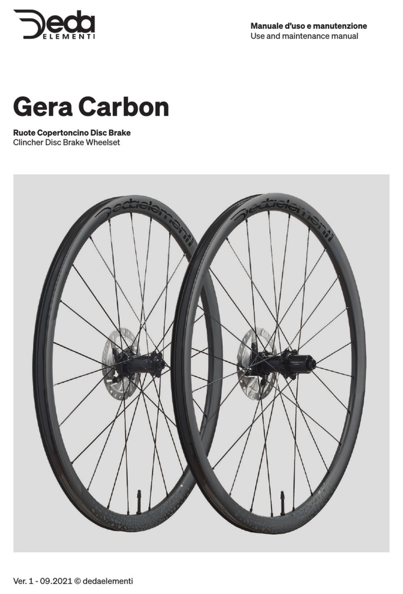
Deda Elementi Gera Carbon User manual

Deda Elementi
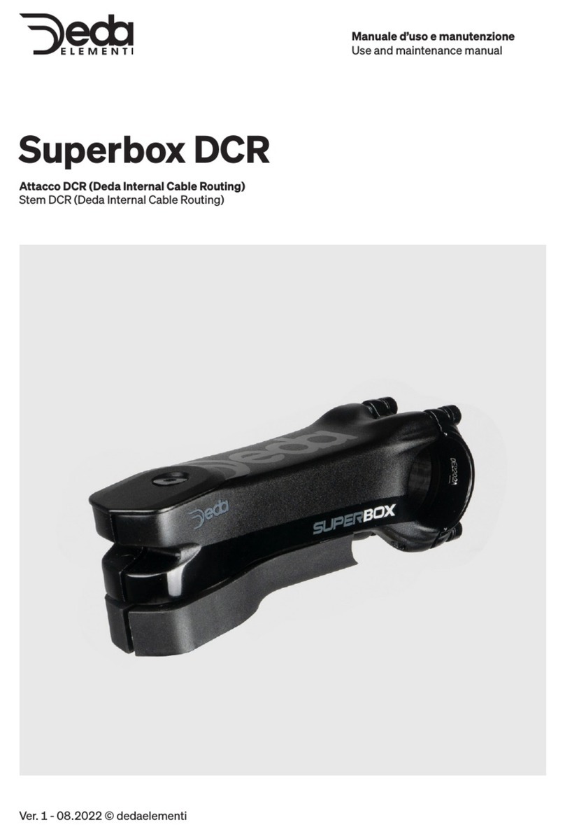
Deda Elementi Superbox DCR User manual

Deda Elementi
Deda Elementi Gera Alloy User manual

Deda Elementi
Deda Elementi SL4DB User manual

Deda Elementi
Deda Elementi ZERO2DB User manual

Deda Elementi
Deda Elementi SL30DB User manual

Deda Elementi
Deda Elementi ZERO2DB User manual

Deda Elementi
Deda Elementi Vinci User manual

Deda Elementi
Deda Elementi Jet Clip-On User manual

Deda Elementi
Deda Elementi WD30ALCL User manual