XLC BV-W17 User manual

Bicycle
Computer
BV-W17 Manual

Contents
1. Item List 1
2. Operation
2.1. How to mount the bracket 2
2.2. How to mount the cycle computer 3
2.3. Installing the Cadence & Speed Sensor 3
2.4. How to mount the magnet 4
2.5. Find out the wheel size 5
3. Nomendature 6
4. Mode Change 7
5. Functionality Setting
5.1. ID SCAN MODE (Pair Up) 8
5.2. CLK MODE (Clock Mode) 8
5.3. TM - or TM + MODE (Timer Count Down or Up) 9
5.4. T. TM MODE (Trip Time Mode) 9
5.5. DST MODE (Distance Mode) 10
5.6. MXS MODE (Maximum Speed Mode) 10
5.7. DST MODE (Distance Mode) 10
5.8. ODO (Total Odometer Mode) 11
5.9. KCAL MODE (Calorie mode) 13
5.10. SCAN MODE 14
5.11. DEFAULT SETTINGS 14
6. Maintenance 15
7. Battery Replacement 16
8. Troubleshooting 17
9. Specications 18
10. Limited Warrenty 19
11. Important Health Notice 20
12. Wheel Size Chart 21

1
Item list
Please check that all the following items have been included before
starting.
Rubber
Bracket
Sensor
Speed Magnet
Cadence Magnet
CY-300 series cycle computer
Nylon ties
Stabling Pads
Chapter 1

Bicycle Computer
2
Operation
Use the rubber to tighten the bracket to the handlebar or stem with
the nylon ties.
2.1 How to mount the bracket
Chapter 2

3
2.2 How to mount the cycle computer
2.3 Installing the Cadence & Speed Sensor
Place the cycle computer on the bracket and secure it in clockwise.
Nylon Ties
Speed Sensor
Stabling Pads
Cadence Sensor
Mount the sensor on top of the left chain stay with
long nylon ties, make sure the cadence side face the
front and speed side face the back. The distance
between the sensor and the cycle computer would
approximately be 150 cm.
Approx.
150cm

Bicycle Computer
4
2.4 How to mount the magnet
Secure the Cadence Magnet on the inner side of crank and
make sure the magnet side faces the cadence sensor zone.
The maximum distance between the cadence sensor and
the magnet on the crank is 5 mm. Once above items are in
the right position, the user may go for a ride.
Note: Initial ashing green light indicates the sensor
detected magnet signals normally. Please make sure
everything has been setup correctly before riding
the bicycle.
Secure the Speed Magnet on the spoke of the back wheel with screw. Make
sure the magnet side faces the speed sensor zone. The maximum distance
between the speed sensor and the magnet on the spoke is 5 mm.
Speed Magnet
Screw Cadence Magnet
Stabling Pads Adjustable
1~5mm
Gr een light
Speed sensor
C adence sensor

5
2.5 Find out the wheel size
Wheel Circumference
To get the accurate result, the wheel size should be correct. Mark the
symbol on the tire and ride one circle. Then measure the length between
two points to get the circumference. Or the user can also get wheel
circumference by the following equation:
Circumference (mm) = 2 x 3.14 x R (inch) x 2.54 (1 inch = 2.54 cm)
R=Radius in centimeter
The user can refer the “wheel size chart”
on page 21 for the wheel size

Bicycle Computer
6
Current Speed
Speed Scale
Symbol
Pedalling Revolution
per Minute
Motion
Signal
Mode
Indicator
PM Indicator
(Post Meridiem)
Mode Key
Set Key
Sub Display
Average Speed
compare to
Current Speed.
Above/Below
Nomenclatur
Chapter 3

7
Mode Change
Chapter 4
CLK Mode (Clock Mode)
12/24H and Time switch
TM- or TM+ MODE(Count Down/Up Mode)
ODO MODE (Total ODO Mode)
T. TM MODE (Trip Time Mode)
T.CAD MODE (Trip Cadence Mode)
AVS MODE (Average Speed Mode)
A.CAD MODE (Average Cadence Mode)
MXS MODE (Max Speed Mode)
M.CAD MODE (Maximum Cadence Mode)
DST MODE (Distance Mode)
KCAL MODE ( Calories Mode)
SCAN MODE (Scan Mode)
Press Mode key shortly to change mode.

Bicycle Computer
8
Functionality Setting
Chapter 5
5.1 ID SCAN MODE (Pair up)
5.2 CLK MODE (Clock Mode)
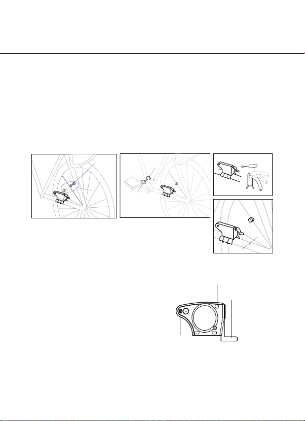
How to pair up the cycle computer with speed/cadence sensor
How to set the Time
Under any mode, press and hold “Set & Mode” keys for 3 seconds to go
ID scan. Kindly place the sensor at maximum allowable distance within 150
cm to the cycle computer. It will pair up the cycle computer to the speed/
cadence sensor automatically. When the percentage shows 100% means scan
completed. ID scan is failed if “Err” sign shows after scan completed. The user
can press “Set” key again to scan again, or hold “Mode” key to exit ID Scan
mode. ID scan will automatically exit after 30 seconds.
Press and hold “SET” key for 3 seconds to set
clock.
Press “SET” key once to adjust 12/24 hours.
The timer will be in COUNT UP if setting is 0:00:00, otherwise it will be
in COUNT DOWN. The TM+ will repeat with ashing digits if it reaches
up to 9:59:59. The TM- will also repeat with ashing digits when the
time set has run out.
Press “MODE” key to
adjust time (hour, minute
and second).
Press “SET” key to adjust timer count down or count up (hour and minute).
Hold “MODE” key for 3 seconds to go back to Clock Mode once the setting is
nished.

9
5.3 TM - or TM + MODE (Timer Count Down or Up)
5.4 T. TM MODE (Trip Time Mode)
Timer Count Down and Count Up will depend on users’ prior setting in Clock
Mode.
Trip Timer would operate automatically when the bike is in motion.
The timer will be in COUNT UP if setting is 0:00:00, or it will be in COUNT DOWN.
The TM+ will repeat with ashing digits if it reaches up to 9:59:59. The TM- will also
repeat with ashing digits when the time set has run out.
How to reset all data
Press and hold “SET” key for 3 seconds, all exercises results in displayer will return
to zero, except odometer.
OR
Set Key
3 Seconds

Bicycle Computer
10
5.5 AVS MODE (Average Speed Mode)
5.6 MXS MODE (Maximum Speed Mode)
5.7 DST MODE (Distance Mode)
The average speed from the beginning onwards.
The maximum speed from the begging onwards.
The trip distance accumulated from the beginning onwards.
Note. If the time or distance is over the max value (29 hr: 59 min: 59 sec or Distance:
999.99km), It will not be able to measure correct average speed by showing “Err” on the
displayer. Once the time & distance value has been reset, the average speed will show
normally.

11
5.8 ODO (Total Odometer Mode)
How to change speed scale and wheel settings
• Under ODO Mode, press “SET” key for 3 seconds to go to
setting.
• Press “SET” key again to select Km/H or Mile/H, press
“MODE” key to go to Wheel Settings.
• Input the correct wheel size by pressing “SET” key, the range
of wheel size from 100mm to 2,999mm.
• Hold “MODE” key for 3 seconds to go back to ODO Mode.
(Refer to Wheel Size Chart)
Note: CY-517C will keep the value of ODO (Total Odometer)
in the memory even after the user changes new battery. The
ODO value cannot be erased by the clear function unless
apply default setting.
Total odometer accumulated from the beginning onwards.
Note: CY-517C will keep the value of ODO (Total Odometer) in the memory even
after the user changes new battery. You can’t set your last value of ODO. This value
cannot be erased by the clear function unless apply default setting.

Bicycle Computer
12
T. CAD
(Trip Cadence Mode)
Trip cadence (pedals revolution per minute) accumulated from
the beginning onwards.
M. CAD
(Maximum Cadence Mode)
Maximum cadence (pedals revolution per minute) from the
beginning onwards.
A. CAD
(Average Cadence Mode)
Average cadence (pedals revolution per minute) from the
beginning onwards.

13
5.9 KCAL MODE (Calorie mode)
Press “SET” key for 3 seconds to go to setting mode.
Press “SET” key again to input weight in numbers, then press “MODE” key to go to
KG or LB Setting.
Press “SET” key to select preferable KG or LB weight scale.
Then, press “MODE” key to go to Gender Setting.
Press “SET” key to select Male or Female gender.
Press and hold “MODE” key for 3 seconds to go back to KCAL Mode.
How to input gender, weight scale and weight
It displays the accumulated calories consumed from the beginning of the trip
onwards.
Note: This accumulated calories display will return to 0 once it has been clear under
the TM MODE.

Bicycle Computer
14
5.10 SCAN MODE
5.11 DEFAULT SETTINGS
Under the SCAN MODE, the display will automatically show all modes in
circulating loop every 4 seconds, once the speed has been detected. Press any
key to stop SCAN feature.
The Default Settings will clear all the measured value except ID CODES. Under
any “Setting modes” (Clock setting, Odo setting or Calorie setting), press and
hold all “MODE” & “SET” keys at the same time for 6 sec until all the values
return to default values.
The default setting will keep the ID Code after all the default values.
6 Seconds

15
Maintenance
Chapter 6
CY-517C cycle computer
If the display contrast changes and gures become faint, it’s time to replace the
battery. Consider changing the computer sensor and transmitter batteries at the
same time.
Note:
Do not expose CY-517C computer to extremely cold or hot temperatures i.e. don’t leave the
unit in direct sunlight for extended periods of time.
Sensor
Check the position of sensor and magnet periodically. For current measurement,
the sensor, magnet should not get wet/ rust, otherwise it may cause function
error.
Bracket / Magnet / Sensor band
These items can be rinsed in surface fresh water or washed with a mild soap.

Bicycle Computer
16
CY-517C computer
Unscrew the back cover. The (+) side should be facing up. Gently remove the
battery and replace it with a new battery model Cr2032.
Sensor
Unscrew the back cover. The (+) side should be facing up. Gently remove the
battery and replace it with a new battery - model CR2032.
Battery Replacement
Chapter 7
Battery Replacement
Chapter 7

17
Troubleshooting
Chapter 8
Q1. Display is black or very light:
The battery power may be low. Try a new battery to make sure the battery is
installed correctly.
Q2. Display becomes dark or black:
The unit is too hot. Place the unit in a shaded area, and it will return to normal.
Q3. The unit operates slowly or struggled:
The unit is too cold. Warm the unit, and it will return to normal.
Q4. Date in display varies enormously:
Check your surroundings for electro magnetic or high energy interference and
move away from the source of interference.
Q5. Data in display shows slowly:
The unit may be affected by low temperature factor but it didn’t inuence the
function reading. When the temperature rises, the data reading/ witch will back
to the normal.
Q6. Current speed does not appear
It may be caused by the following situation: the distance & position between
magnet and sensor to adjust or low battery power.

Bicycle Computer
18
Specifications
Chapter 9
Receiver Speed Censor /
Cadence
Operating
Temperature 0 ºC~ 40 ºC 0 ºC~ 40 ºC
Storage Temperature -10 ºC~ 50 ºC -10 ºC~ 50 ºC
Emitted Frequency N/A 122k ± 5%
Battery 3 volt lithium 2032 cell 3 volt lithium 2032 cell
Weight 30.6 grams 20 grams
Timer Range: 0~29 (hour): 59 (minute): 59 (Second)
Current Speed Range: 0~99.9 KM/ 0~62.4 Mile
average Speed Range: 0~99.9 KM/ 0~62.4 Mile
MAX Speed Range: 0~99.9 KM/ 0~62.4 Mile
(Trip) Distance Range: 0~999.99 KM/0~624.99 Mile
Odometer Range: 0~99999 KM/ 0~62499 Mile
KCAL: 0~99999 kcal
Table of contents
Other XLC Bicycle Accessories manuals