ACCO Brands SEAL 62 Base User manual

62/54Base
Mounter and Laminator
User Manual
“A” Version Models, Rev B
October 2017

English
All rights reserved
All information included in this manual as well as information included in supplements or addendum to this manual is
subject to copyright law. This information shall not be used, copied, reproduced, transmitted or disclosed to third parties
without our prior written consent.
SEAL® assumes no responsibility for any errors that may appear in this document nor does it make expressed or implied
warranty of any kind with regard to this material, including, but not limited to, the implied warranties of merchantability and
fitness for a particular purpose.
SEAL® shall not be liable for incidental or consequential damages in connection with, or arising out of the furnishing,
performance, or use of this document and the program material which it describes.
2017 ACCO Brands USA
LLC

Warranty and Safety instructions 3
English
INTRODUCTION
Thank you for purchasing your SEAL® 62/54 Base.
Maximum effort has been invested in the design of this machine to give you years of reliable
service.
As you become familiar with your machine you will appreciate the high quality of its output and the
excellence in engineering stated in its smartly styled design.
The machine described in this manual is a multi-functional machine that can perform the following
processes;
high-quality lamination,
panel mounting of images,
mounting and laminating in one pass,
decaling.
This manual gives a general description of various processes.
A vast number of laminating products are available. All of them with their own applications and
processing specifications.
For more details on film choice and application solutions refer to the SEAL® films and adhesives
product catalog.
THIS MANUAL
This manual is intended for the user of the 62/54 Base. Read this manual carefully before starting
the machine.
This manual contains important information for correct installation, operation and maintenance of
the machine. It also contains important instructions to prevent accidents, personal injury and/or
serious damage prior to or during operation of the machine.
Familiarize yourself thoroughly with the functioning and operation of this machine and strictly
observe the directions given. If you have any questions or need further details on specific aspects
related to this machine, please do not hesitate to contact us. The address and phone number are
stated on the copyright page.
Chapter 1 will provide you with a summary of the manufacturers warranty information.
It also describes the safety features installed on the machine and gives a number of safety
instruction and warnings. Read this chapter carefully.
Chapter 2 provides a general description of the machine and of the process principles to help first
time users to find their way on this machine.
Chapter 3 specifies the machine and the materials to be used on this machine.
Chapter 4 guides you through the installation and decommissioning of the machine.
Chapter 5 guides you through the operation in various processes to develop basic knowledge of the
machine.
Chapter 6 provides maintenance procedures and trouble shooting suggestions in case the results
are not up to your expectations.
Chapter 7 is the glossary and explains a number of terms used in this manual.

TABLE OF CONTENTS
1Warranty and Safety instructions 6
1.1 Warranty 6
1.1.1 Warranty conditions 6
1.1.2 Warranty period 6
1.2 End of Life (EOL) Statement 6
1.3 Safety 7
1.3.1 Safety features 7
1.3.2 Safety instructions 8
1.4 Warnings 8
1.4.1 General ESD-warning 8
1.4.2 In this manual 8
1.4.3 On the machine 9
2Description 9
1.1. General description 10
2.1 Parts identification 10
2.2 Process principle 11
3Specifications 12
3.1 Identification 12
3.2 Machine dimensions 12
3.3 Material specifications 13
3.4 Machine specifications 13
3.5 Optional features 13
4Installation 14
4.1 Unpacking 14
4.2 Installation 15
4.3 Transport 16

Warranty and Safety instructions 5
English
5Operating 17
5.1 Process controls 17
5.1.1 Control panel 17
5.1.2 Additional controls 19
5.2 Operating modes 20
5.2.1 Normal mode 20
5.2.2 Slow mode 21
5.3 Placing film rolls 21
5.3.1 Auto-grip shafts 22
5.3.2 Loading shaft with film rolls 23
5.4 Webbing 24
5.4.1 Release liner and splitter bars 24
5.4.2 Using the upper section only 25
5.4.3 Upper and lower section 25
5.4.4 Presetting the tension 26
5.4.5 Pressure setting 27
5.5 Processes and settings 28
5.5.1 Mounting images or decals 28
5.5.2 Pre-coating panels 29
5.5.3 Over-lamination 29
5.5.4 Single-sided lamination 29
5.5.5 Decaling 30
5.6 Unloading 30
6Maintenance 31
6.1 Cleaning 31
6.1.1 Cleaning the silicone covered rollers. 31
6.2 Preventive maintenance 32
6.2.1 Auto-grip shafts 32
6.3 Troubleshooting 32
6.4 Technical assistance 33
7Process Control Sheet 34
8Glossary 35

1 Warranty and Safety instructions
1.1 Warranty
The warranty period and conditions stated in this chapter are merely a summary of the general
SEAL® warranty conditions.
For the exact details on the warranty period and conditions for your machine, please contact your
dealer.
1.1.1 Warranty conditions
The manufacturer warrants to the original end user* that the machine when proven defective in
materials or workmanship, within the applicable warranty period will be repaired, or (at our option)
replaced without charge.
Note: The main rollers are subject to normal wear and tear and therefore have warranty on
material defects only.
The manufacturer or its representative shall not be liable for any damage caused by the machine
nor loss of productivity.
Warranty is voided when:
Changes or modifications are made to this machine, not explicitly approved by the
manufacturer,
The machine is changed or modified by unauthorized persons,
The machine is used under other than normal working conditions,
The machine is used for purposes other than intended for (see page 3).
* The original end user is the person that first purchased the machine from the manufacturer or its
representative.
1.1.2 Warranty period
The standard warranty period on this machine is one year from the date of purchase.
This period however can be longer due to local law or purchase agreement.
The main rollers have a warranty period of 6 months on material defects only.
The warranty ends when:
The periods stated above have expired.
The machine changes possession.
Warranty is voided by any of the conditions mentioned above.
1.2 End of Life (EOL) Statement
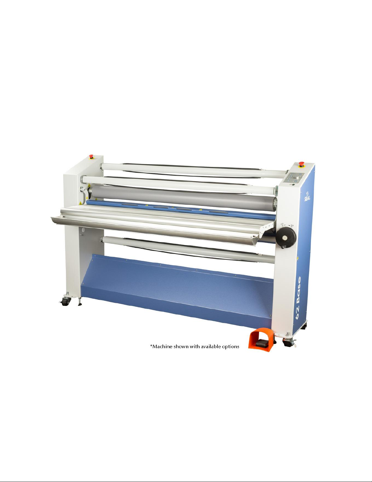
Your SEAL® 62/54 Base has been designed to provide years of reliable and trouble free service,
but at some point in time it may be necessary to retire this unit from service. To protect our
Environment specific guidelines and requirements should be followed.
This machine is primarily constructed from steel sheet metal and contains no hazardous materials.
This system has electrical components that must be removed from the machine and disposed of
according to country, regional or local requirements.
The SEAL® 62/54 Base is Industrial Equipment as stated in Category 6 of Annex 1A of the EU
(Waste of Electrical and Electronic Equipment) WEEE Directive 2012/19/EU. This Directive as
of 2014 applies to this equipment type, and in the future this Directive should be reviewed for
any changes that may now apply.

Warranty and Safety instructions 7
English
1.3 Safety
This machine is provided with safety equipment to promote safe machine operation.
The manufacturer has done everything possible to prevent any possible danger and to inform you
as accurately and comprehensively as possible of any hazards relating to the operation of the
machine.
You should nevertheless proceed with caution when operating the machine.
Read the safety instructions below and familiarize yourself with the warning symbols summarized in
the Warnings section.
1.3.1 Safety features
1.3.1.1 Emergency stops
The machine has 2 emergency stops. When activated the machine will come to a complete stop
and the power to the motor controller is switched off. The emergency stops must be disengaged
before a restart is possible.
1.3.1.2 Optical safety devices
The machine has an optical safety device at the front side of the nip at the main rollers. These
devices perform a check of the operation between transmitter and receiver.
When an error is detected (e.g. the signal is interrupted) the motor will stop and the motor controller
will be disabled.
The stop signal from the optical device is overruled when the slow mode is selected and the
footswitch is pressed or when the reverse button is held. An audible signal is heard to warn for
posible danger.
1.3.1.3 Safety footswitch
The safety footswitch is used as remote control to start and stop the machine in the normal and the
slow mode.
WARNING:
THE OPTICAL SAFETY DEVICE IS DISENGAGED WHEN USING THE SAFETY
FOOTSWITCH IN SLOW MODE.
KEEP CLEAR OF THE NIP WHEN PRESSING THE FOOTSWITCH, WHILE SLOW
MODE IS ACTIVE.
1.3.1.4 Slow mode
The slow mode is used when setting up the machine with new films or images.
When in slow mode the machine is started with the footswitch it will run at low speed so that the
operator has both hands free to position and feed new film or image correctly into the machine.

1.3.2 Safety instructions
Work safely!
The owner of the machine is responsible for safe operation of the machine. He therefore is obliged
to familiarize operating personnel with the contents of this manual and make them aware of all
possible hazards.
Do not change, remove or disable the safety facilities.
1.4 Warnings
1.4.1 General ESD-warning
WARNING:
DANGER OF ELECTRIC SHOCK BY ELECTROSTATIC DISCHARGE.
PROCESSING FILMS THROUGH LAMINATING ROLLERS WILL CAUSE BUILD-
UP OF ELECTROSTATIC CHARGES.
Maintaing room humidity between 50% and 70% is the best preventive measure to reduce static
buildup.
1.4.2 In this manual
In this manual you will find 3 levels of warnings.
WARNING:
THE WARNING MESSAGE IS USED WHEN A LIFE-THREATENING SITUATION
MAY ARISE OR PERSONAL INJURY CAN OCCUR.
FOLLOW THE INSTRUCTIONS CLOSELY.
CAUTION:
The caution message is used when there is danger of damage to the machine or
materials.
Follow the instructions to prevent this damage.
Note:
This message is used to give you useful information for easier operation, to prevent waste of
material, etc..

Warranty and Safety instructions 9
English
1.4.3 On the machine
On the machine (See Figure 1) you will find the following warning symbols in black on a yellow
background.
ROTATING PARTS (3)
DANGER OF GETTING INJURED BY ROTATING PARTS.
MAKE SURE THAT THESE ROTATING PARTS DO NOT CATCH
YOUR FINGERS, CLOTHING, HAIR, ETC.
This symbol is placed on each cabinet just above the splitter bar (3).
ROTATING PARTS (1)
DANGER OF GETTING INJURED BY ROTATING PARTS.
MAKE SURE THAT THESE ROTATING PARTS DO NOT CATCH YOUR FINGERS,
CLOTHING, HAIR, ETC.
This symbol is placed on in-feed table arms and on the cabinets just above the output table (1).
ESD SHOCK (2)
DANGER OF GETTING AN ELECTRIC SHOCK CAUSED BY ELECTROSTATIC
CHARGE BUILD-UP IN THIS AREA.
This symbol is placed on those places where electrostatic charges can be build-up. The machine
parts close to the nip and the output material are most likely building up charges. Therefore ESD-
symbols are placed on the image guide (2)
Figure 1: Warning symbol locations.
Description

This chapter describes the machine and its operating basics.
1.1. General description
The machine described in this manual is a mono-directional machine dedicated for processing
pressure sensitive materials.
While feeding through images and the coating films, the two silicone coated main rollers generate
the pressure.
The area where the upper and lower main roller meet is called the “nip”. The upper main roller can
be moved up or down manually, so the nip can be varied to feed materials of various thicknesses.
The nip setting hand wheel also sets the pressure for the laminating process.
The lower main roller is motor driven. The speed can be manually set between zero and a given
maximum value.
The top roller is equipped with a heater to assist in the lamination process. The heat assist makes
the adhesive more active and allowes it to spread more evenly, which improves the results.
The machine has two material unwind shaft positions in the rear. The supports in the upper front
position can clamp a (plastic) cilinder used for release liner wind-up.
The machine can be divided into an upper and a lower section.
The upper section, above the in-feed table, is suitable for unwind material with release liner.
The lower section can only unwind material without release liner.
1.5 Parts identification 1 Castors
2 Foot switch
3 Unwind shaft
4 Nip setting and pressure control wheel
5 Main rollers
6 In-feed table
7 Image guide
8 Wind-up shaft
9 Heat assist switch
10 Control panel
11 Emergency button
12 Splitter bars
13 Heater
14 Output table
15 Identification label
16 Main power entry
Figure 2: Main parts identification.

Warranty and Safety instructions 11
English
1.6 Process principle
In all processes the materials are fed through the nip from the front side to be joined together by
pressure.
A process that makes maximum use of the machine is shown in Figure 3. Shown is a double sided
laminating (decalling) process.
The top coating film is a pressure sensitive film with release liner (3) taken from a supply roll on the
(rear) upper unwind shaft (5). The bottom coating film is a pressure sensitive (mounting) film without
release liner taken from a supply roll on the lower unwind shaft (9).
Figure 3: Creating Pop-up art, including image supply from roll.
The image that has to be coated on both sides is fed between the main rollers (1) via the in-feed
table (2).
When using a pressure sensitive laminate, it often has a release liner (3) that has to be removed. As
in the top half, it runs via a splitter bar (6) where the release liner is removed. This release liner is
rolled up onto the wind-up shaft (4) in the upper section.
When using a pressure sensitive laminate without a release liner (like in the bottom section), it must
not run via the splitter bar to avoid the film sticking to the bar and leaving adhesive residue behind.
A mounting film has adhesive on both sides and release liner on just one side. This release liner has
to stay on until the image is mounted. So a mounting film is processed in the bottom section the
same way as a laminate without release liner.
The upper main roller can be heated (7) to a fixed temperature of 40C. This is called ‘heat assist’
and can be used to activate the adhesive to flow more evenly and get a better bonding between
laminate and image.

2 Specifications
2.1 Identification
The machine identification label (example in Figure 4) is located at the bottom of the right-hand
cabinet, on the rear side of the machine.
This label indicates the model (version) and the rated power of the machine.
CAUTION: THE POWER SUPPLY MUST BE ABLE TO PROVIDE THE RATED POWER
ACCORDING TO THE ELECTRICAL CODE REQUIREMENTS FOR THE AREA OF
INSTALLATION. CONSULT YOUR LOCAL ELECTRICIAN FOR THE POWER SUPPLY
REQUIREMENTS.
Figure 4: Machine identification labesl (example).
2.2 Machine dimensions
Uncrated:
Metric
American
Model Type
54
62
Unit
54
62
Unit
Width
190.5
207.5
cm
75
81.7
in.
Height
130.8
130.8
cm
51.5
51.5
in.
Depth (excl. table)
47
47
cm
18.5
18.5
in.
Depth (incl. in-feed table)
63.5
63.5
cm
25
25
in.
Working height
90
90
cm
35.4
35.4
in.
Weight
232
252
kg
512
556.3
lbs
Crated:
Width
221.7
221.7
cm
87.3
87.3
in.
Height
155
155
cm
61
61
in.
Depth
90
90
cm
35.4
35.4
in.
Weight
270
293.4
kg
595
646.5
lbs
Working area:
Width
342
358.5
cm
135
141.5
in.
Depth
190 cm (75 in.) + 2x maximum board length
Note: A relative humidity between 50% and 70% helps reducing ESD build-up.

Specifications 13
English
2.3 Material specifications
Maximum width: Metric American
Process up to 40°C (104 °F) –62 Base 1600 mm 63 in.
- 54 Base 1400 mm 55.1 in.
Maximum roll diameter: (same both models)
Material unwind (upper unwind) 240 mm 9.4 in.
Material unwind (bottom unwind) 305 mm 1 ft.
Release liner wind-up 160 mm 6.3 in.
Maximum panel thickness: 50 mm 2.0 in.
Roll core inside diameter: 76.2 mm 3.0 in.
2.4 Machine specifications
Power ratings:
Europe 1N/PE 230VAC +/- 10%, 50/60Hz, 9.0A
USA - 62 Base 1N/PE 115VAC +/- 10%, 50/60Hz, 16.0A
- 54 Base 1N/PE 115VAC +/- 10%, 50/60Hz, 15.0A
(NEMA 5-20 plug supplied)
For the correct supply voltage version refer to the identification label on the machine.
Standard number of shaft positions:
Material unwind 2 (auto-grip)
Release liner wind-up 1
2.5 Optional features
The 54/62 Base “A” version has several options available. They are:
Item
Description
Part number
1
54 Base Infeed Trough Option
64619A
2
62 Base Infeed Trough Option
64614A
3
Leveling feet Option
5406A
4
54 Base Image Guide
64624A
5
62 Base Image Guide
64625A
6
Option 54 Base Lower Take-up W/ Plastic AutoGrip
64620
7
Option 62 Base Lower Take-up W/ Plastic AutoGrip
64618
8
POWER REAR TAKE UP OPTION 62 BASE
64623
Contact your sales representative or a customer service representative for more information.
Note: Some options may be included with your model.
Nip setting: 0–52 mm 0 –2.05 in.
Pressure: 0.3–1.0 N/mm 1.71 –5.71 lbf/in.
Process speed:
Maximum 5 m/min 16.4 ft/min
Slow mode 0.9 m/min 3.0 ft/min
Maximum roller temperature: 40 °C 104 °F
Noise level <70 dB(A)

3 Installation
WARNING:
INSTALLATION MUST BE CARRIED OUT BY SKILLED PERSONNEL.
3.1 Unpacking
At delivery, the machine is packed in a plastic bag to avoid moisture penetration. It is transported in a
carton box and is fastened onto a wooden pallet.
Place the pallet in a space where there is enough room to roll the machine off from the pallet (approx.
6 m).
WARNING:
ROLL THE MACHINE OFF WITH 2 PERSONS. IT IS HEAVY AND CAN NOT BE
CONTROLLED ALONE.
To unpack, follow the steps below (refer to Figure 5);
1. Cut the straps.
2. With another person, lift off the carton box and remove any loose packing material.
3. Remove the plastic bag and put the accessories aside.
Figure 5: Ramp positioning.
4. Remove the four securing bolts (1) and stabizing blocks.Remove screws holding center support
and remove support.
5. Unscrew wood screws holding the ramp (4). Place the ramp (4) against the roll-off side of the
pallet so that the castors (5) will run clear from the edge.
6. With another person, roll the machine off carefully from the pallet using the ramp.
Note: Save all packing material for later if moving over long distances or discard of according to
local regulations.

Installation 15
English
3.2 Installation
Note:
Make sure that the machine, in its final
location, has adequate space. You will
need room to feed, receive and trim
images. See Figure 6.
L = Maximum board length,
S = Minimum space 60 cm.(24”).
Figure 6: Working space.
1. Move the machine (and the accessories) to its final location.
2. Remove all transport material.
Cut the straps around the shaft supports and remove the foam pads,
Cut the straps holding the in-feed table arms,
Cut the straps around the main roller axis and move up the top main roller to remove the
transport blocks from the nip,
3. Secure machine in place with foot by stepping on the fromt caster’s locking mechanisms. (See
figure 6.)
Note: An uneven floor may affect lamination quality. In the case of an uneven floor, please contact
customer service for the machine leveling option.
WARNING:
MACHINE MUST BE SECURED IN PLACE BEFORE USING.
Figure 7 : Securing machine
Locking
Lever
OFF
ON

CAUTION: Check the mains values before connecting. See section 2.4 for power
supply details. Only if absolutely necessary, use an extension cable of ample capacity.
Unroll the extension cable completely.
4. Connect the machine to the mains using the power cable supplied with the machine. Minimum
recommended service, standard 50Hz or 60Hz, single phase 230VAC 13A with breaker not
exceeding 16A or single phase 115VAC 20A with a breaker not exceeding 20A.
WARNING:
MAKE SURE THE POWER SUPPLY CABLE AND/OR THE EXTENSION CABLE IS
NOT BLOCKING YOUR WAY AROUND THE MACHINE.
3.3 Transport
The machine can be transported on a smooth surface on its castors.
CAUTION:
Unlock front wheel before moving machine.
When moving the machine on rough surfaces or over long distances, use the original pallet and
packing material and and move it with a pallet truck or forklift.

Operating 17
English
4 Operating
This chapter describes the function of the controls and indicators, the operating modes, how to set
up and operate the machine and a number of applications. The sections in this chapter are placed in
a sequence in which the information is needed for laminating processes. For the mounting process
the sections 4.3 and 4.4 can be skipped with the exception of setting the pressure (see section
4.4.5).
4.1 Process controls
This section gives an overview of the functions of the controls on the control panel (7) and
elsewhere on the machine (Figure 8).
Note: Switch on the heat assist approximately 15 minutes before use, if a process requires the
rollers to be heated, close the nip and run the machine at low speed to avoid uneven hot spots.
4.1.1 Control panel
This paragraph describes the controls and indicators on the control panel.
Figure 8: Control panel
Control ON/OFF (1), toggle pushbutton and standby or ON indication LED;
Press the switch 1 second to switch the machine from stand by to active and back.
The LED flashes when the machine is in stand-by mode.
WARNING:
THE MACHINE IS CONSTANTLY POWERED WHEN THE POWER CORD
IS PLUGGED IN.

Pressure indication (2), 4 LED’s;
The LED’s indicate the pressure setting of the main rollers. When 2 LED’s light at the same
time, they indicate the tens in between. See specifications for actual pressure range. All four
LED’s flashing indicates a pressure or nip setting error.
The LED’s start flashing at 10% overload. When the pressure exceeds a 20% overload an
audible signal is generated. Increase the nip to lower the pressure.
Speed control (3), control knob;
Sets the speed anywhere in a range between 0 and 10 (See specifications for actual speed
range).
Slow mode (4), toggle pushbutton;
Press 1 second to switch slow mode ON or OFF.
To run at slow mode speed the footswitch must be pressed.
The LED will light when slow mode is selected.
CAUTION:
When slow mode is active the machine can still run at high speed.
Slow mode indication is NOT a speed indication. It is a working method.
Safety indicator (5), LED;
The LED will light up when the beam of the optical safety device at the input side of the nip is
not interrupted.
Forward (6), pushbutton;
Press to start the rotation of the rollers in the forward direction.
The LED will light when the forward mode is selected.
When the LED flashes it indicates a motor overload. Press the stop button and check the
material flow and the tension setting of the unwind shafts.
Reverse (7), snap pushbutton;
Press and hold for rotation of the rollers in reverse direction.
The LED will light when the reverse mode is selected.
When the LED flashes it indicates a motor overload. Press the stop button and check the
material flow and the tension setting of the wind-up shafts.
Forward and reverse indicator flashing;
This indicates a system error. Disconnect and then reconnect the power. If the error persists,
contact your service organization.
Stop (8), pushbutton;
Press to stop the rotation of the rolls.
Heat-assist (9), ON/OFF switch
Switches the heat-assist control ON or OFF. When ON the upper roller will be heated until it
reaches 40 °C or 104 °F. Allow ample time to reach this temperature.

Operating 19
English
4.1.2 Additional controls
Figure 9: Additional controls
Emergency stop buttons (1), push and hold button;
When pressed the rotation of the rolls is stopped immediately and the button is locked into this stop
position. The safety indicator LED will flash while the button is depressed.
Turn the button to unlock it.
Pressing start, reverse or pressing the footswitch starts the process again.
Nip setting wheel (2), geared wheel;
Turn the wheel clockwise to narrow (close) the nip and set pressure or
counter-clockwise to release pressure and widen (open) the nip.
When both rollers touch the materials, the pressure is set. By turning the wheel clockwise the
pressure is increased. Turning the nip setting wheel counter-clockwise the pressure will decrease.
The pressure is indicated on the control panel by 4 LED’s.
Foot switch (3), snap switch;
Press and hold the switch to start the rotation of the rolls. Insert the forefoot completely to disable
the safety lock that prevents accidental starting.
When the switch is released, the rotation of the rolls will stop.
In-feed table (4)
The in-feed table can swing up around the pivot point at the top of the table arms.
The image guide is clamped to the table arms and can be removed by pulling it forward from its
retaining blocks.
Unwind tension control (5), ring;
By turning this ring counter-clockwise (top to rear) an amount of friction is set between the shaft and
the frame, so this will act as a brake.
Tightening the brake will apply more tension to the material on the shaft.
Turning the ring clockwise (top to front) will release the brake and therefore release the tension.

4.2 Operating modes
The machine is either in normal mode, or slow mode.
4.2.1 Normal mode
When slow mode is not activated (normal mode), the rotation speed of the rollers is set via the
speed control knob.
Start rotation by pressing the forward button or the footswitch.
Rotation stops when a stop button is pressed or the footswitch is released.
Note:
To return control from the footswitch to the control panel without stopping, press and hold the
forward button, release the footswitch and then release the forward button.
An interruption of the light beam of the optical safety device in front of the rollers will also stop the
rotation of the rollers. To continue after the interruption is taken away, the process must be started
again.
4.2.1.1 Reverse
WARNING:
KEEP CLEAR OF THE REAR SIDE NIP WHEN RUNNING IN REVERSE MODE.
When running in reverse, the optical safety device at the front side nip is ignored. An audible tone is
heard to warn you for posible danger. The speed is preset and works the same as slow mode. The
rollers will only turn in reverse while the reverse button is held.
This manual suits for next models
3
Table of contents
Other ACCO Brands Laminator manuals