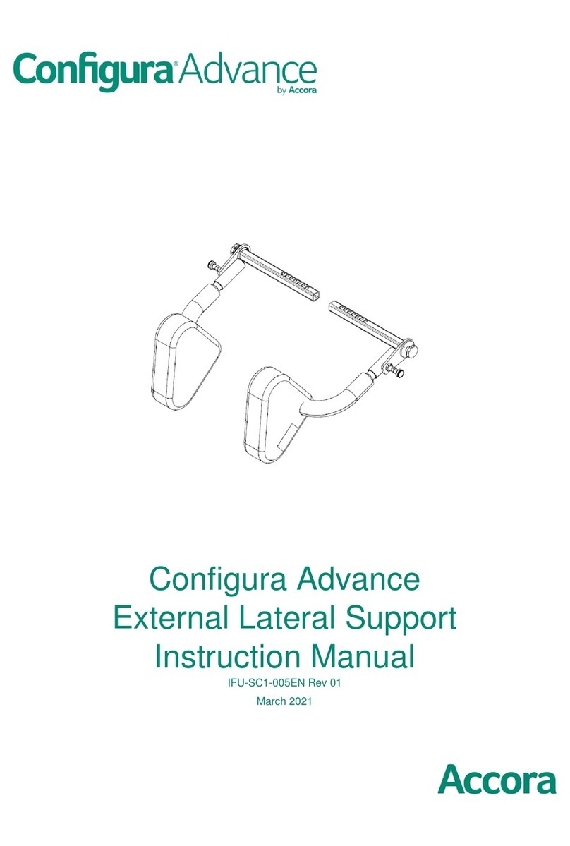
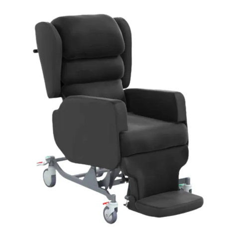
Accora Configura Advance User manual

Configura Advance Postural
Backrest and External Laterals
Instruction Manual
IFU-SC1-003EN Rev 02
March 2021

2
Contents
Title Page
Welcome 2
1. Technical Specification 3
2. Assembly of Postural Backrest 4
3. Setup of Postural Backrest 7
4. Assembly of External Laterals 8
5. Setup of External Laterals 8
6. Functionality Check 9
7. Cleaning and Disinfection 9
8. Guarantee 9
9. Disposal 9
10. Contact details 10
Design Policy and Copyright
® And ™ are trademarks belonging to Accora
Ltd unless otherwise stated. As our policy is one of
continuous improvement, we reserve the right to
modify designs without prior notice. © Accora Ltd
2020.
Welcome
Dear Customer,
Thank you for purchasing an Accora healthcare
product. We feel sure that this product will
exceed your expectations.
This manual is important for understanding how to
use your new Configura Advance Postural
Backrest and External Laterals; please read it
before use. If you need further information,
please contact Accora.
See Contact Details in Section 10.
Note: For clarity, the Postural Backrest and
External Laterals are generally shown in this
Instruction manual without cushions.
Before using the Configura Advance Postural
Backrest, you must read and understand the
instructions in this user manual. All actions and
handling of the Configura Advance Postural
Backrest must be performed in accordance
with the instructions in this manual.
Any actions that are inconsistent with the
manual are performed at your own risk and
Accora shall not be liable for any injury or
damage. Please ensure that the manual is
available to users and operators throughout
this products service life.
This instruction manual must be read in
conjunction with the Configura Advance
chair instruction manual (IFU-SC1-001EN).
WARNINGS
A clinical assessment and risk assessment MUST
be carried out by suitably trained and
qualified personnel before fitting this
accessory to the chair.
Refer to the Configura Advance chair
instruction manual (IFU-SC1-001EN) for full list
of safety warnings.

3
1. Technical specification
The table below lists the part numbers for the
Advance Postural Backrest and External Laterals.
Part number
Description
BRPOSKT-0-SC1-030
Postural backrest includes
all metal frames and
cushions
EXTLAT-0-SC1-020
External laterals, set of 2
Part number
Compatibility
BRPOSKT-0-SC1-030
All SC1, SC2, SC3, SC4
models with brown fabric
EXTLAT-0-SC1-020
Figure 1 shows the position of the adjustable parts of
the postural backrest and the external laterals.
1. Top wing open/close adjustment ClickLock
plunger.
2. Top wing tilt angle adjustment ClickLock plunger.
3. Top wing depth adjustment lock plunger.
4. Middle wing open/close adjustment ClickLock
plunger.
5. Middle wing depth adjustment ClickLock plunger.
6. Wing height adjustment lock plunger.
7. Lateral support thumb screw.
Two types of locking mechanism are used:
•ClickLock plunger (Figs 2 & 3).
•Lock plunger (Figs 4 & 5).
To unlock the ClickLock plunger, turn the plunger
through 180 degrees; the plunger will lift out and lock
into the unlocked position.
To lock the ClickLock plunger, turn the plunger through
180 degrees; the plunger will drop into the locked
position.
To unlock the lock plunger, pull out and hold.
To lock the lock plunger, release and the plunger will
drop into the locked position.
1
2
3
4
5
6
7
Figure 1 –backrest adjustments
Figure 2 –ClickLock
plunger locked
Figure 3 –ClickLock
plunger unlocked
Figure 4 –lock plunger
locked
Figure 5 –lock plunger
unlocked

4
2. Assembly of Postural Backrest
1. Remove the chair sidepieces. Pull out the locking
plunger (Fig 6, Item 1) located under the seat of
the chair on each side and rotate 90 degrees to
lock it open. Release the hand screw (Fig 6, Item
2) on each side of the chair. Pull the sidepieces
away from the chair.
2. Remove the Backrest hand lever (Fig 7 Item 1) and
the Tilt-in-Space hand lever (Fig 7 Item 2, if fitted)
by removing 2 x cross head screws on each lever
clamp. Leave the control cables connected and
lay the levers to one side. Retain the screws for
refitting.
3. Remove the R-clip (Fig 8, Item 1) and clevis pin (Fig
8, Item 2) from the top fixing of the backrest
actuator (Fig 7, Item 3 & 4; Fig 8).
4. Remove control box if fitted. Press the tab (Fig 9.
Item 1) and slide the control box down to release it
from the mounting. Lay it aside carefully.
5. Remove the backrest hinge covers (Fig 10, Item 1)
from the backrest pivot points (Fig 10, Item 2). Fold
the backrest forwards (Fig 7, Item 5).
4
5
①
②
1
2
Figure 6
Figure 7
Figure 8 –top of backrest actuator
1
2
3
1
2
Figure 9
1

5
6. The backrest hinges each side of the chair are
secured with shoulder bolt (Fig 11, Item 1), three
M10 plain washers (Fig 11, Item 2), M8 plain washer
(Fig 11, Item 3) and self-lock M8 nut (Fig 11, Item 4).
Note the order of assembly.
7. Remove the bolts, washers, and nuts from both
hinges with 5mm Allen key and 13mm spanner
(Figure 12) and lift off the backrest. Retain the
fasteners to use with the postural backrest.
8. Place the postural backrest on the chair frame
(Figure 13) and refit the bolts, washers, and nuts
(Figure 11) to the hinges. Ensure the M10 washers
are fitted over the shoulder of the bolts, and the
M8 washer is fitted on the threaded part.
9. Refit the backrest actuator into the clamp on the
postural backrest. Refit the clevis pin and R clip
(Figure 8).
10. Refit the backrest hand lever (Fig 14, Item 1) and
Tilt-in-Space hand lever (Fig 14, Item 2) in the
positions shown in Figure 14. Ensure the Tilt-in-
Space operating cable (Fig 15, Item 1) is routed
between the backrest and backrest actuator
assembly.
Figure 10 –(Seat cushion shown removed for clarity.)
2
1
1
2
Figure 11
1
2
Figure 12
Figure 13
Figure 14
3
4
2
2

6
11. Refit the control box if required. Place the control
box against the plastic fixing bracket on the
Postural Backrest, locate the control box in the
sliding slot, then move control box upwards.
Ensure the fixing tab (Fig 9, Item 1) has located the
control box correctly.
12. Fit the backrest hinge covers over the backrest
pivot points. To fit this cover, place the first part of
the cover (Fig 16, Item 1) over the rear part of the
hinge protection plate (Fig 16, Item 2), then pull
the front part of the cover (Fig 16, Item 3) down
over the hinge.
13. Figure 17 shows the backrest hinge cover from the
inside. Place the lower pocket of the backrest
hinge cover (Fig 17, Item 1) over the lower part of
the hinge protection plate (Fig 16, Item 4) to
secure the hinge cover in place.
14. Repeat steps 11 and 12 to secure the cover on the
other side.
15. Refit the sidepieces. To fit the sidepieces, pull out
the plunger located under the seat on one side of
the chair (Fig 6, Item 1) and rotate it through 90
degrees to lock it open.
16. Undo the hand screw (Fig 6, Item 2).
17. Locate the two sidepiece fixing bars into the chair
frame. Push the sidepiece all the way in (Fig 18)
and release the plunger by rotating it until the cap
engages with the base (Figure 19).
18. Ensure the plunger is engaged by moving the
sidepiece in and out –the sidepiece should not
move.
Figure 16 –(Seat cushion shown removed for clarity.)
2
1
3
4
1
Figure 17
Figure 18
Figure 19
Figure 15
1

7
19. Tighten the hand screw to secure the sidepiece
(Fig 6, Item 2).
20. Repeat steps 14 to 18 to fit the other sidepiece.
21. Carry out a functionality check as described in
Section 7.
3. Setup of Postural Backrest
1. Height –to adjust the backrest height, pull out
and hold the two lock plungers shown in red in
Figure 20. Move the backrest to the desired
height, then release the plungers to lock the
backrest in position (Fig 1, Item 6).
2. Depth of top and middle pillows –to adjust the
pillow depth, unlock the two ClickLock plungers
shown in red in Figure 21 that correspond with
the pillow to be moved and move the backrest
pillows to the desired depth setting. Release the
plungers to lock the pillow depth (Fig 1, Items 3 &
5).
3. Angle of outer parts of pillows –to adjust the
angle of the outer parts of the pillows unlock the
relevant ClickLock plunger shown in red in Figure
22 and adjust to the desired angle. Release the
ClickLock plungers to lock the angle adjustment
(Fig 1, Items 1 & 4).
Figure 20
Figure 21
Figure 22

8
4. Inclination of top pillows –to adjust the
inclination of the top backrest pillows, release
the two ClickLock plungers shown in red in Figure
23 and adjust the angle as desired. Release the
ClickLock plungers to lock the angle (Fig 1, Item
2).
4. Assembly of External Laterals
Slide each external lateral into the locating points (Fig
24, Item 1) on the postural backrest. Secure the
External Laterals by tightening the thumb screws
shown in red slowly clockwise. Move the external
laterals in and out a small amount until a locking
position is located. Then tighten the thumb screws
down (Fig 24, Item 2).
5. Setup of External Laterals
1. Width of the external laterals –turn the thumb
screws shown in red (Fig 25, Item 1) counter
clockwise to release the external laterals. Adjust
the width as required, then tighten the thumb
screws (Fig 1, Item7).
2. Angle of the external laterals –turn the thumb
screws shown in red (Fig 26, Item 1- there is a
second screw hidden from view on the other
side of the backrest) to release the external
laterals. Move the arm away from the sliding bar
and adjust the angle as required. Then locate
the arm on to the sliding bar again and tighten
the thumb screws.
Figure 23
Figure 24
1
2
Figure 25
1
1
Figure 26

9
3. Removing the external laterals –lift the lock
plunger shown in red in Figure 27 and remove
the external laterals. To refit, lift the lock plunger
and slide the external laterals into position.
Release the lock plunger and move the external
lateral in and out slightly to ensure the lock
plunger engages.
6. Functionality Check
These checks must be carried out after backrest
assembly, adjustment, or maintenance.
1. Check the backrest is secure by rocking it
backwards and forwards.
2. Check the backrest hinge pins and clips are fitted
correctly (Figure 11).
3. Ensure the ClickLock plungers move easily and
that the wings adjust through the full range (Figure
1).
4. Check that all lock plungers are located in
adjustment holes (Figure 1).
7. Cleaning and Disinfection
Cleaning Information:
To disinfect the chair, only use detergents designed for
use in healthcare e.g. warm soapy water. Do not use
abrasives, scourers or other materials that could
damage the coating. Do not use corrosives, caustics or
strong acids.
Do not use detergents that could alter the structure or
behaviour of the plastics (petrol etc.).
Clean by wiping with a damp cloth. Alternatively use
Microfibre cleaning cloth without any soap.
For extreme soiling use a 5% Sodium Hypochlorite
solution.
The chair is not designed for maintenance in
automatic chair washers or for cleaning with
pressurised water, spraying, showering or steam
cleaning.
Accora cannot be liable for any damage or risk of
damage if inappropriate cleaning or disinfectant
agents are used.
Cleaning procedure:
1. Disconnect the chair from the power supply (if
applicable).
2. Move the chair to where cleaning will take place
and lock the chair castors.
3. Remove the cushions and any accessories such as
profiled headrest, external laterals.
4. Clean as described in the “Cleaning Information”.
8. Guarantee
Model
Configura Advance Postural
Backrest & External Laterals
Warranty period
2 years
9. Disposal
In the event of the disposal of materials from the chair,
end-of-life parts must be disposed of in accordance
with current environmental regulations.
WARNING
Functionality check MUST be carried out by
suitably trained and qualified personnel.
Check for obstructions around, above and
below the chair frame and position the chair
so that it can operate through the full
adjustment range without any chance of
obstruction or entrapment.
Always engage the castor brakes when the
chair is stationary or left unattended.
WARNING
The chair must be disconnected from the
power supply when being cleaned or
disinfected.
All functions MUST be tested and approved by
a competent person after cleaning or
disinfection.
The chair MUST be cleaned and disinfected
before re-using the chair for a different
patient.
Figure 27

10
10. Contact details
UK and Rest of World
USA
Address
Accora Ltd.
Charter House
Barrington Road
Orwell
Cambridge
SG8 5QP
UK
Accora Inc.
9210 Corporate Blvd. Suite 120
Rockville
MD 20850
USA
Telephone
+44 (0)1223 206100
+1 301-560-2400
Email
information@accora.care
Website
www.accora.care
www.accora.care

11
This page is intentionally left blank

12
IFU-SC1-003EN Rev 02
April 2020
Other manuals for Configura Advance
1
Table of contents
Other Accora Indoor Furnishing manuals
Popular Indoor Furnishing manuals by other brands

Milano
Milano DRHOOK installation guide

Brunner
Brunner finasoft 6722/AG Instructions for use

CONFORAMA
CONFORAMA Along Assembling Instruction

Tradecraft Specialties
Tradecraft Specialties BASEBL-2 instruction manual

Forte
Forte SWXK311 Assembling instructions

Furniture of America
Furniture of America Niketas CM7860Q Assembly instructions