Accora EMPRESA NSB-0-FL6-000 User manual

Empresa Instruction Manual
IFU-FL6-001EN Rev 02

2
Contents
Title Page
Product Overview ---------------------------------------------3
General Warnings-------------------------------4
1. Means of Delivery ----------------------------------5
2. Safety Instructions----------------------------------5
3. Use Environments----------------------------------6
4. Intended Use-----------------------------------------6
5. Technical Specification----------------------------7
6. Accessories ------------------------------------------8
7. Electrical Specification-----------------------------8
8. Assembly ---------------------------------------------9
9. Assembly of Side Panels (optional) ---------- 11
10. Bed Controls and Indicators-------------------- 14
11. Floor-level Function ------------------------------ 16
12. Length Adjustment ------------------------------- 17
13. Functionality Check ------------------------------ 18
14. Using the Castor Brakes------------------------ 18
15. Mattress Selection-------------------------------- 19
16. Siderail Selection --------------------------------- 20
17. Moving and Repositioning---------------------- 20
18. Cable Routing for Mattress Pump ------------ 21
19. Cleaning & Disinfection-------------------------- 22
20. Troubleshooting----------------------------------- 23
21. Storage---------------------------------------------- 24
22. Daily Inspection ----------------------------------- 24
23. General Maintenance---------------------------- 25
24. Guarantee ------------------------------------------ 25
25. Disposal--------------------------------------------- 25
26. EMC Statement ----------------------------------- 26
27. Table of Symbols --------------------------------- 30
28. Contact Details ------------------------------------ 31
Welcome
Dear Customer,
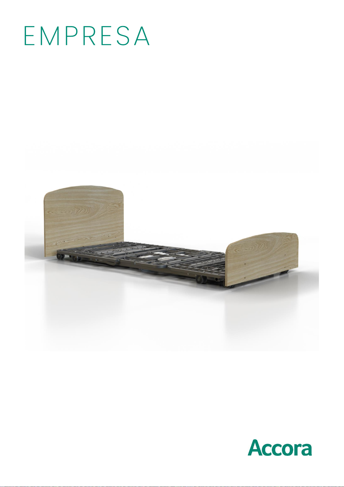
Thank you for purchasing an Accora
healthcare product. Before operating the
bed, you must read and understand all the
instructions in this manual. All actions and
handling of the bed must be performed in
accordance with the instructions in this
manual.
Please ensure that the manual is available to
users and operators throughout the bed’s
service life.
If you need further information, please
contact us. See section 28 for region specific
contact details.
General
The Empresa is classified as a Class 1
Medical Device in accordance with the
Medical Device Regulation 2017/745.
Notice to User
If a serious incident occurs in relation to this
medical device, affecting the user or the
patient, then the user or patient should report
the serious incident to the medical device
manufacturer (or distributor) and, in the
European Union, the user should also report
the serious incident to the Competent
Authority in the member state where they are
located.
Accora Ltd, 38 Main Street,
Swords, Co. Dublin, Ireland, K67 E0A2
T: +353 (0)1 695 0614
Design Policy and Copyright
® and ™ are trademarks belonging to Accora Ltd
unless otherwise stated. As our policy is one of
continuous improvement, we reserve the right to
modify designs without prior notice. © Accora Ltd
2020.

3
Product Overview
1. Headboard (design may vary)
2. Footboard (design may vary
3. Mattress platform
4. Handset
5. Central brake lever
6. Braked castors (NSB-0-FL6-
000 only)
7. Power cable
8. Mattress guides
9. UDI Label
10. Manufacturers nameplate inc.
serial number
11. Legrest actuator
12. Main lift actuator –Head end
13. Backrest actuator
14. Main lift actuator –Foot end
15. Control Box
16. Side panel (optional)
17. Side panel centre bracket
18. Side panel end bracket
19. Headboard bracket
1
2
3
4
5
6
7
8
16
13
18
19
14
12
17
11
10
9
15
Headboard
Footboard

4
General Warnings ---------------
1. Keep this Instruction Manual available
for future reference.
2. These instructions must be observed
to ensure the safe and effective use of
this bed and the safety of users and
caregivers.
3. This bed must be assembled,
positioned and used in accordance
with these instructions.
4. The safety features for operating the
bed and instructions concerning the
bed must be strictly observed.
5. This bed must not be exposed to
smoke, naked flame, extreme
temperature, flammable gases or other
hazardous substances or situations.
6. Do not smoke in or around the bed.
7. Accora shall not be held liable for any
damage, injuries or accidents arising
from unauthorised modifications, non-
genuine spare parts, negligence or
use that is at variance with this manual
which can result in serious injury or
death.
8. Electrical equipment can be hazardous
if misused or abused. Ensure the
electrical supply cable is not damaged
by crushing and does not create a trip
hazard.
9. Inappropriate routing of accessory
cables, e.g. mattress air pump cable,
could lead to dangerous electric
hazards if squeezed or crushed
between moving parts. The bed must
not be used if there is any visible
damage to any cables.
10. When routing cables for other
electronic equipment used with the
bed (e.g. air mattress pump), ensure
cables cannot be squeezed, crushed
or damaged by the moving parts on
the bed.
11. Inappropriate use of the power supply
cable (e.g. kinking, shearing) could
lead to dangerous electric hazards.
The bed must not be used if there is
any visible damage to this cable.
12.
12. The hand control should be positioned
to avoid strangulation risk.
Inappropriate use of the hand control
(e.g. kinking, shearing) could lead to
dangerous electric hazards. The bed
must not be used if there is any visible
damage to the handset or cable.
13. Electrical installations must meet local
requirements.
14. Only use side rails, and other
accessories, that are compatible with
this bed as supplied by Accora.
Incompatible side rails can create
hazards and entrapment risks.
15. Keep children and pets away from this
bed unless supervised by an adult as
there is a risk of injury and/or choking
on small parts.
16. Never stand on the bed.
17. Do not lower the bed while a hoist that
extends beneath the bed is being
used. Hoist access is obtained when
the bed is raised to 45cm measured
from the floor to the mattress platform
base.
18. The bed should be left in the floor-level
position when the patient is
unattended in order to reduce risk of
injury due to falls.
19. If using the electronic functions
adversely affects the health of the
patient, disconnect the power supply
and only use the bed in the static
mode.
20. Do not move the bed when it is in the
floor-level position.
21. This bed should not be used for
transporting patients in vehicles.
22. This bed is not recommended for
users outside of the weight and height
specifications detailed in Section 5
23. Before operating this bed, ensure the
patient is safely positioned to reduce
the risks of bed fall and entrapment.
24. Always check for any entrapment risks
under the bed before lowering to the
floor-level position.

5
1. Means of Delivery---------------------------
The bed is supplied boxed with the electrical
system fully assembled. The headboard and
footboard and any accessories are supplied
separately.
An inspection must take place upon receipt
to ensure the delivery is complete and
undamaged.
Any missing parts, faults or damage must be
reported immediately to the carrier and
Accora in writing.
If the bed needs transporting between
facilities, consider if the headboard and
footboard should be removed. Ensure
manual handling guidelines are followed.
2. Safety Instructions-------------------------
1. Before using the bed, you must read the
instruction manual and use the bed in
accordance with it.
2. The bed must not be used if faults have
been detected on it that may injure the
patient, staff or a third person, the bed or
the surroundings.
3. The bed must only be operated by
persons who are able to operate it in
accordance with the manual.
4. The operating staff must make the patient
aware of the control functions that apply
to the patient subject to an assessment
by a professional.
5. Before using the bed, the operator should
understand the bed and its functionality.
6. The safe working load, as specified in
Section 5, must never be exceeded.
7. If there is a patient on the bed, the bed
castors must be locked as an unlocked
bed castor can result in movement of the
bed and injury to a patient who leaves the
bed or changes position.
8. The height of the mattress platform must
be adjusted to the correct height for the
condition of the patient.
9. Only one person should occupy the bed
at any time.
10.When operating the moving parts of the
bed, care must be taken to ensure that
the patient, other people and objects do
not become trapped.
11.If a lifting pole or infusion stand is fixed to
the bed, increased attention must be
taken during movement, lifting or tipping,
to the space around the lifting pole and
infusion stand, so that the equipment is
not damaged.
12.Before cleaning the bed, the electrical
supply must be disconnected.
25.Patients, or users, should be risk
assessed to ensure they are able to
understand this manual and to operate
Empresa safely without risk to
themselves or others.
26.If the combined weight of the mattress
and accessories exceeds 35kg, the
maximum patient weight must be
reduced accordingly.
27.Take care when moving the bed over
door thresholds.
28.In high ambient temperatures electrical
enclosures (e.g. handset) may get
warm during prolonged use.
29.When moving the bed, the power cable
must be disconnected from the wall
socket and secured on the bed to
avoid damage to the cable.

6
3. Use Environments--------------------------
This bed is intended for use in the following
application environments:
1. Application Environment 3 - Long-term
care in a medical area where medical
supervision is required and monitoring is
provided if necessary and ME equipment
used in medical procedures may be
provided to help maintain or improve the
condition of the patient. Note, this
includes use in nursing homes and in
rehabilitation and geriatric facilities.
2. Application Environment 4 - Care
provided in a domestic area where ME
equipment is used to alleviate or
compensate for an injury, disability or
disease.
3. Application Environment 5 –Outpatient
(ambulatory) care, which is provided in a
hospital or other medical facility, under
medical supervision where ME
equipment, is provided for the need of
persons with illness, injury or disability for
treatment, diagnosis or monitoring.
Electrical installations must meet local
requirements.
4. Intended Use ---------------------------------
The Empresa is intended to be used as a
nursing bed in the Use Environments listed.
The patient user group for the bed is adult
patients above 146cm in height who do not
exceed the maximum patient weight of
240kg.
Subject to a risk assessment, the bed may
help to maintain, improve, compensate or
alleviate the condition of the patient.
A risk assessment must be carried out before
the bed is used by a patient.

7
5. Technical Specification-------------------
The table below lists the Empresa part
numbers; some models may not be available
in your region. Part numbers may be suffixed
(EU, US etc) to show regions.
Part
number
Description
NSB-0-FL6-000
•Four section profiling
•Height range 10-80cm
•Mattress platform 200x90cm
•SWL 275kg
•Max user weight 240kg (38st)
•Individually braked castors at both ends
•Head and footboards supplied
separately
NSB-1-FL6-000
•Four section profiling
•Height range 10-80cm
•Mattress platform 200x90cm
•SWL 275kg
•Max user weight 240kg (38st)
•Individually braked castors at head end
•Centrally braked castors at foot end
•Head and footboards supplied
separately
NSB-2-FL6-000
•Four section profiling
•Height range 3.9-31.5in, 10-80cm
•Mattress deck/platform 80x36in,
200x90cm
•SWL 600lb, 275kg
•Max user weight 525lb, 240kg (38st)
•Centrally braked castors at both ends
•Head and footboards supplied
separately
Environmental information:
Condition
Temperature
Range
Relative
Humidity
Atmospheric
pressure
Meters
above sea
level
Operating
+5°C to +40°C
+41°F to +104°F
20% to 80%
(Non-
condensing)
700 hPa to
1060 hPa
Max. 3000
meters
Transport/
storage
-10°C to +50°C
14°F to +122°F
If the bed is stored in conditions outside the
normal operating range, it should be allowed
time to stabilise, in normal operating
conditions, before use.
The Empresa mattress platform range
including maximum angles:
Figure 5.1
** The safe working load is calculated as
follows (as specified by EN 60601-2-
52:2015):
Maximum patient weight: 240kg 38st 522lb
Mattress 20kg 3st 44.5lb
Accessories 15kg 2st 33.5lb
TOTAL (Safe working load) 275kg 43st 600lb
0° - 70°
0° - 36°
Lorem ipsum
Description
Value
Overall dimensions
1015mm W × 2090mm L
40in W x 82.3in L
Mattress size
See mattress selection –
section 15
Bed castor
83mm diameter
NSB-0-FL6-000
8 x 63mm castors, 4 braked
and 4 unbraked
NSB-2-FL6-000
8 x 63mm castors, central
brake at both ends
Mattress platform height
100mm to 800mm
3.9in to 31.5in
Maximum trapeze self-assist
pole lifting load
75kg/165lbs
Safe Working Load**
275kg / 600lbs
Maximum Patient Weight**
240kg / 525lbs / 38st
Audible noise
<60 dBA
Mass of Bed
120kg / 265lbs
Liquid ingress protection
IPX6
Trendelenburg function
12 degrees
Expected service life
Typically 5 years

8
6. Accessories ----------------------------------
Due to differing regulatory requirements, not
all the accessories are available in all
regions.
Description
Part number
Standard (200cm) fabric siderail set
SDR-0-FL6-000
Extended (220cm) fabric siderail set
SDREX-0-FL6-000
Folding siderail (Standard)
SDRFLD-0-FL6-000
Folding siderail (Wide - for use with
width adjustment kit)
SDRFLDW-0-FL6-000
Folding siderail bumper
SDRFLDBP-0-FL6-000
Width adjustment kit (extends width
of bed by 15cm)
WDEX-0-FL6-000
Standard bed lever assist bar
STLEV-0-FL6-000
Lifting pole
LIFOL-0-FL6-000
Head & footboard bumper set for
standard headboard
BMHNE-0-FL6-000
Head & footboard bumper set for
use with fabric siderails
BMHNE-H-FL6-000
Wall protection bar
WALLB-0-FL6-000
Note: the bed lever cannot be fitted to the
bed at the same time as the fabric siderail or
the folding siderail.
7. Electrical Specification -------------------
Duty Cycle: Intermittent operation 2 min/18
min. After the maximum continuous action of
two minutes, there must be a break of 18
minutes.
Description
Value
Supply voltage
100 –240V
Supply frequency
50/60Hz
Maximum supply current
3.9 Amps
Degree of protection against
liquid ingress
IPX6
Degree of protection against
electrical shock
Class II Double Insulated
Symbol
Definition
The B symbol indicates this product has a degree of
protection against electric shock for type B
equipment.
IPX6
Degree of protection against liquid ingress.
Do not dispose of in household waste.
Degree of protection against electric shock: Class II
Double Insulated.
For indoor use only
For or a full list and explanation of symbols
used see Section 27.

9
8. Assembly--------------------------------------
The left and right of the bed are as seen by a
person lying in the bed. See figure below.
1. Check that the delivery is complete and
whether any visible damage has occurred
to the bed during transport.
2. Remove the packaging and identify all the
components:
Bed frame
1. Mattress platform.
2. Handset.
3. Mattress guides (4 off).
4. Headboard & footboard brackets and fixings.
5. Headboard & Footboard (supplied separately).
6. Side panels and fixing bracket (optional, supplied
separately).
Figure 8.1
3. There are two handset ports located on
either side of the bed as shown by 1 (right
side) and 2 (left side) on Figure 8.2. The
bed will be delivered with the handset
cable plugged into the socket in position 2
on the left side.
Figure 8.2
WARNING
Assembly MUST be carried out by
suitably trained and qualified personnel.
All functions MUST be tested and
approved after assembly by suitably
trained and qualified personnel.
Assembly MUST take place in a clear,
uncluttered area and children and pets
should be kept away.
If bed has become soiled or contaminated
during transit refer to cleaning and
disinfection instructions.
Ensure headboard and footboard are
assembled as shown below so that the
Trendelenburg function works correctly.
1
2
3
4
5
6
1
2
Footboard
Headboard
Right
Left

10
Figure 8.3
4. To move the handset cable to the right
side of the bed, remove the handset
cable connector from the left side socket.
Insert the captive blanking plug into the
socket.
5. Remove the plug from the right side
socket and insert the handset cable
connector.
6. Ensure the bed is positioned so that the
mains plug can be easily put into a mains
socket. Plug the power supply cable into
a mains supply socket.
7. Using the handset, raise the bed to the
highest position, see section 10.
8. The headboard and footboard fixing kit
comprises the following items:
1. 2 x left fixing brackets
2. 2 x right fixing brackets
3. 8 x M8 x 20 bolts
4. 8 x M8 x 35mm bolts
5. 24 x M8 washers
6. 8 x M8 locking nuts
7. 1 x 5mm Allen key
9. Position the brackets on the footboard as
Figure 8.4 –note the orientation of the
brackets.
Figure 8.4
10.Fix the brackets to the footboard using
the M8 x 35 bolts, nuts, and washers
provided as shown in Figure 8.5. Tighten
using the 5mm Allen key and a 13mm
spanner.
Figure 8.5
11.Repeat steps 9 and 10 to mount the
brackets to the headboard.
12.Take the footboard and locate the
mounting brackets into the channel
sections on either side of the foot end of
the bed; slide the footboard and brackets
all the way into the channels as Figure
8.6.
13.For the bed at the standard length for a
200cm mattress, use the bolt holes
marked ‘Standard’ in Figure 8.5. For the
bed at the extended length for a 220cm
mattress, use the bolt holes marked
‘Extended’ in Figure 8.5.
Figure 8.6
Standard
Extended

11
14.Align the bolt holes and secure the
mounting brackets using the M8 x 20mm
bolts and washers provided as shown in
Figure 8.7. Tighten using the 5mm Allen
key.
Figure 8.7
15.Repeat steps 12 and 14 to mount the
headboard to the head end of the bed.
16.Install the four mattress guides as shown
in Figure 8.9 (note the orientation) in the
locations shown in Figure 8.8. They may
be fitted in any position within the
locations shown.
Figure 8.8
Figure 8.9
17.Carry out the Functionality Check in
Section 13.
18.The Empresa is now ready for use.
9. Assembly of Side Panels (optional)
1. The two side panels will be supplied
with a fixing kit which contains:
1. 4 x side panel end brackets
2. 2 x side panel middle brackets (each comprising a
plate and claw)
3. 24 x M6 x 20 bolts
4. 24 x M6 washers
5. 1 x 4mm Allen key
2. The side panel end bracket is shown
below in Figure 9.1.
Figure 9.1

12
3. The side panel middle bracket is shown
below in Figure 9.2. The claw may be
fitted to the plate in one of four positions,
depending on the configuration of the
bed:
1. Bed 105cm wide with folding siderail fitted.
2. Bed 105cm wide without folding siderail.
3. Bed 90cm wide with folding siderail fitted.
4. Bed 90cm wide without folding siderail.
Figure 9.2
4. Fit the claw to the plate in the correct
position for the bed configuration using
two M6 x 20 bolts and M6 washers.
Leave the bolts slightly loose.
5. Fit the four side panel end brackets to the
bottom edge of the head and footboards
with the M6 x 20mm bolts and washers
as shown in Figure 9.3. Leave the bolts
slightly loose.
Figure 9.3
4
3
2
1
Claw
Plate

13
6. Fit the assembled middle bracket to the
side panel. There are two sets of fixing
holes on each side panel, depending
which side of the bed the side panel is
fitted, as shown in Figure 9.4. Fit the
bracket to the set of holes closest to the
headboard using the M6 x 20 bolts and
M6 washers as shown in Figure 9.5.
Tighten the bolts using the 4mm Allen
key.
Figure 9.4
Figure 9.5
7. Mount the side panels onto the bed frame
as shown in Figure 9.6. Position the side
panel between the headboard and
footboard and fit the centre bracket claw
over the bed frame side bar.
Figure 9.6
8. Fit each side panel to the side panel end
brackets with the M6 x 20mm bolts and
M6 washers as shown in Figure 9.7.
Leave the bolts slightly loose.
Figure 9.7
9. Adjust the side panels so they are fitted
snugly against the headboard and
footboard. Tighten the bolts previously
left loose using the appropriate Allen key.
10.Carry out the functionality check in
Section 13.
Headboard

14
10. Bed Controls and Indicators------------
The handset is used by the user or caregiver
to change the position of the of the backrest
and legrest sections and to adjust the height
of the mattress platform of the bed. Always
check for obstructions before the bed is
raised or lowered. Before using the control,
the operating staff should explain to the
patient how the bed can be positioned. If the
medical staff state that the patient’s medical
condition is inappropriate for the patient to be
able to adjust the bed independently, the
bed’s position must only be adjusted by the
caregiver.
The handset has the following controls and
indicators:
Figure 10.1
WARNING
Bed positioning MUST be carried out by
suitably trained and qualified personnel.
Patients should only be allowed to
operate the bed independently if they are
able to understand the safety instructions
in this manual and have been risk
assessed as appropriate to do so.
Make sure the castor brakes are in the
locked position before using the handset
to change the positions of the bed.
Always engage the brakes when the bed
is stationery or left unattended.
Check for obstructions around, above and
below the bed frame and position the bed
so that it can operate through the full
height range without any possibility of
obstruction or entrapment.
Use of the legrest function must be risk
assessed as it may cause unintentional
displacement when used with patients of
smaller stature.
Sharing the bed with a patient (particularly
a child) carries the risk of lying on the
patient and causing suffocation or the
patient being wedged against the side of
the bed.
Use of wedges, supporting and
positioning devices may cause
entrapment and a risk of suffocation.
Smaller patients may need additional
support to achieve a semi-Fowler’s
position.
Always store the handset in a safe place
when not in use to avoid risk of
strangulation and entrapment in the bed
mechanism, for example on the outside of
the headboard or footboard.
Handset and cable must be kept out of
reach of children.
1
3
5
8
2
4
6
7
10
12
11
9

15
Note: If the patient is unable to operate the
bed safely, lock the handset immediately
after each use.
Safety stop position
The safety stop position is the position the
bed will stop at when lowering the bed using
button 6. The mattress platform height will be
approximately 20cm. To use the floor level
function, refer to Section 11.
Handset lockout function
To prevent unauthorised or accidental
operation the handset can be locked out.
Press button 1 and button 12 together for 3
seconds; the handset will beep slowly to
indicate that the handset is locked.
To unlock the handset, press button 1 and
button 12 together for 3 seconds; the
handset will beep quickly to indicate that the
handset is unlocked.
Reset to flat-and-level function
The bed can be returned to a position where
the mattress platform is level by pressing and
holding button 7 until the bed stops moving.
Trendelenburg function
To set the mattress platform in the
Trendelenburg position (head down), press
buttons 8 and 10 together.
To set the mattress platform in the Reverse
Trendelenburg position (head up), press
button 9.
Backrest –Raise / Lower
Legrest –Raise / Lower
Mattress Platform –Raise / Lower
Reset to flat and level position
Function safety button (must be
pressed together with button
number 6 or 10)
Reverse Trendelenburg and
Trendelenburg function
Chair position and Semi-Fowler’s
position
1
3
5
9
2
4
6
8
10
12
7
11

16
11. Floor-level Function -----------------------
The floor-level function will lower the
mattress platform to floor level. The mattress
platform height will be 10cm.
To lower the bed to the floor-level position:
1. Check underneath the bed to make sure
there are no obstructions or entrapment
risks.
2. When lowering the bed, make sure the
user or patient keeps hands and legs
away from the edge of the mattress.
3. Press button 6 to lower the bed until it
reaches the safety stop position (approx.
20cm).
4. Press buttons 6 and 8 together. The bed
will now move down to the floor-level
position. The bed will move slower
between the safety stop position and the
floor-level position.
NOTE: If either of the buttons are
released, the bed will stop moving
immediately.
5. When the bed has reached the floor-level
position, store the handset in a safe
place.
6. To raise the bed from the floor-level
position, press button 5.
WARNING
Extreme care must be taken when using
the floor-level function.
Always check for any entrapment risk and
obstructions under the bed before and
during use of the floor-level function.
Keep children and pets away from the bed
unless supervised by an adult.
Patients, users and operators must be risk
assessed and made aware of the risks to
themselves and those around before
using the floor-level function of this bed.
Beware of trip hazard when the bed is in
the floor-level position.

17
12. Length Adjustment------------------------
The Empresa can be extended by 9cm at the
head end and 9cm at the foot end. Refer to
section 15 for the appropriate length setting
for the mattress being used.
To extend the bed:
1. Undo the bolts shown in Figure 12.1 on
each side of the bed and retain the bolts
and washers.
Figure 12.1
2. Slide the head/foot board outwards as
Figure 12.2 until the holes in the
headboard bracket marked ‘Extended’ in
Figure 12.3 line up with the mounting
holes on the bed frame.
Figure 12.2
Figure 12.3
3. Secure the head/foot board with the bolts
and washers in the extended position as
shown in Figure 12.4.
Figure 12.4
4. If required, repeat steps 1 to 3 for the
other end of the bed.
Note: if side panels are fitted, you will need
to purchase longer side panels before the
bed can be extended.
Extended
Standard

18
13. Functionality Check------------------------
Using the handset, test all bed functions and
check all cables for risk of crushing. Refer to
Section 10 - Bed Controls and Indicators:
1. Raise the bed to full height (button 5)
2. Lower the bed until it stops at the safety
stop position (button 6)
3. Lower the bed to the floor-level position
(buttons 6 & 8 pressed together)
4. Check all cables for risk of crushing.
5. Raise and lower the backrest (buttons 1 &
2).
6. Raise and lower the legrest (buttons 3 &
4).
7. Check the Reverse Trendelenburg
function (head up, feet down) (button 9).
8. Check the Trendelenburg function (head
down, feet up) (buttons 8 & 10 pressed
together).
9. Check the correct function of the castors
and brake control.
14. Using the Castor Brakes-----------------
There are two types of castors fitted to the
Empresa, depending on model.
Care must be taken to make sure the castor
brakes are always locked when the bed is in
use, being assembled or dismantled, so that
the bed does not move accidentally.
Standard castor brake
1. To lock the castor, press the lower part of
the brake lever (marked lock) as indicated
in Figure 14.1 until the lever locates in the
new position.
Figure 14.1
2. To release the brake, press the upper
part of the brake lever (marked free) as
indicated in Figure 14.2 until the lever
disengages.
Figure 14.2
WARNING
Functionality check MUST be carried out
by suitably trained and qualified
personnel.
Check for obstructions around, above and
below the bed frame and position the bed
so that it can operate through the full
height range without any chance of
obstruction or entrapment.
Always engage the brakes when the bed
is stationery or left unattended.

19
Central castor brake
1. To lock the brake, press firmly
downwards on the side of the pedal with
the red label as shown in Figure 14.3 until
it locates.
Figure 14.3
2. To unlock the brake, press firmly
downwards on the side of the pedal with
the green label as shown in Figure 14.4
until the brake releases.
Figure 14.4
15. Mattress Selection--------------------------
All mattresses must be fitted and used in
accordance with the mattress manufacturer
or supplier’s instructions.
The following table shows the correct bed
settings for the different mattress sizes that
can be fitted.
If the width adjustment kit (WDEX-0-FL6-
000) is fitted, a mattress of width 105cm may
be used. Refer to the width adjustment kit
instructions for use for more information.
Mattress size
Width adjustment kit
WDEX-0-FL6-000
Length setting (See
section 12)
200cm x 90cm
Standard length /
standard width
Not required
Standard setting at head
and foot end
220cm x 90cm
Extended length /
standard width
Not required
Extended setting at head
and foot end
200cm x 105cm
Standard length /
extended width
Required
Standard setting at head
and foot end
220cm x 105cm
Extended length /
extended width
Required
Extended setting at head
and foot end
WARNING
Incompatible mattresses can create
hazards and entrapment risks. Read
instructions for use.
The distance from the top of the un-
compressed mattress to the top of the
siderail, if fitted, must always be 220mm
or greater.
Bed extension MUST be carried out by
suitably trained and qualified personnel.
Please contact Accora for
compatible mattresses.
Incompatible mattresses
can create hazards and
entrapment risks.

20
16. Siderail Selection---------------------------
There are two types of siderail available from
Accora for the Empresa: the folding siderail
and the fabric siderail. Note: these siderails
are not available in all regions.
Description
Part number
Folding siderail standard
SDRFLD-0-FL6-000
Folding siderail wide*
SDRFLDW-0-FL6-000
Fabric siderail 2000mm long
SDR-0-FL6-000
Fabric siderail 2200mm long
SDREX-0-FL6-000
Before fitting or using any siderails you must
refer to their respective instruction manuals.
Siderails and the bed lever cannot be fitted to
the bed at the same time.
*This must only be fitted onto beds which
already have the width adjustment kit fitted
(WDEX-0-FL6-000).
17. Moving and Repositioning --------------
1. Ensure the bed is at the safety stop
position (see Section 10).
2. Disconnect the power supply cable.
3. Secure the handset, power supply and all
cables to prevent damage.
4. Unlock the castors (See Section 14) and
move the bed as required.
5. When the bed has been moved or
repositioned, lock all the castors.
6. Reconnect the power supply cable and
perform full functionality check as
described in Section 13.
WARNING
Only use side rails that are compatible
with this bed as supplied by Accora.
Incompatible siderails can create hazards
and entrapment risks.
WARNING
Moving or repositioning MUST be carried
out by suitably trained and qualified
personnel.
All functions MUST be tested and
approved by a competent person after
moving or repositioning.
Do not move the bed in the floor-level
position.
Do not move or reposition the bed with
service user or patient on the bed.
Do not move the bed when the power
supply is plugged in to the mains supply
socket.
When moving or repositioning the bed,
disconnect the power supply, secure the
power cable on the bed and do not allow
cable loops to get snagged or caught.
Take care when moving the bed over door
thresholds.
This manual suits for next models
2
Table of contents
Other Accora Indoor Furnishing manuals
Popular Indoor Furnishing manuals by other brands

Furniture of America
Furniture of America CM6957OT Assembly instructions

Bunkers
Bunkers LoLine Assembly instructions

Costway
Costway KC56890 manual

EXPEDO
EXPEDO DITA R5D Assembly instruction

Walker Edison
Walker Edison W70FP18 Assembly instructions

Home Decorators Collection
Home Decorators Collection DIGBY 18 instruction manual