Accordance Systems araid 5000 User manual


1
User's Manual V1.3
I. Safety and Cautions 3
1. Introduction of RAID 0 and RAID 1 3
2. Directions for Use 3
II. Product Content and Accessories 4
III. Introduction of the Product 5
1. Product Features 5
2. Product Specifications 6
3. System Requirements 6
4. Description of Components 7
IV. ARAID Setup 8
1. Hardware installation 8
2. Starting and Operation (for RAID 1 Mode only) 10
3. Local Monitoring 12
4. Network Management (Linux version is for optional purpose) 12
5. Checking for ARAID 5000 compatible drives 13
V. ARAID T5000 (External model) 14
1. Description of Components 14
2. Types (Host Interface) of ARAID T5000 15
VI. ARAID LCD Message Comparison Table (for RAID 1 User) 16
VII. FAQ (for RAID 1 User) 18
VIII.Product Warranty and After-Service 20
IX. Contact Us 21
Thank you for purchasing our product.
・Before using, please read this user's manual carefully in order to set up correct and
safe operation.
・This user's manual at an accessible location for easy reference whenever required.
・The specifications and the appearance of this product may change subject to
improvements without prior notice.
Table of Contents
Accordance and ARAID are registered trade marks of Accordance Systems Inc.
www.accordancesystems.com www.accordance.com.tw

2
User's Manual
Tables
Table 1: RAID 0 vs RAID 1 3
Table 2: Product Content and Accessories 4
Table 3: ARAID 5000 Specifications 6
Table 4: Hardware Installation Steps 8
Table 5: Starting and Operation 10
Table 6: Specifications of ARAID T5000 14
Table 7: Types of ARAID T5000 External Model 15
Table 8: ARAID LCD Message Comparison Table 16
Table 9: PQR Product Error Report Sheet 21
Figures
Fig. 1: Checking the Hard Disk Quality with ARAID EYE PLUS software 3
Fig. 2: Installing Hard Disk for the Optional Tray 4
Fig. 3: Front View of ARAID 5000 7
Fig. 4: Rear View of ARAID 5000 7
Fig. 5: Hardware Installation Steps 9
Fig. 6: ARAID EYE PLUS 12
Fig. 7: Network Management System 12
Fig. 8: Front View and Rear View of ARAID T5000 14

3
I.Safety and Cautions
*
*
(1) RAID 0: Using two hard disks, the usable capacity is two hard disks. However,
there’snobackupmechanism,itwouldbeimpossibletoretrievethedataonceit
is lost or damaged.
(2) RAID 1: Using two hard disks, the usable capacity is one hard disk with backup
mechanism. If one of the hard disks is damaged, then the other one immediately
takes over operation.
*Distinction of RAID 0 and RAID 1 (two 8TB hard disks as an example)
(2) When using the ARAID, you are not required to process the new hard disk with
FDISK and FORMAT steps in advance, and you will be able to execute the
backup of hard disk directly with the automatic rebuilding function.
(3) Before using, be sure to confirm that the power equipment is properly connected
and stabilized to ensure the product will operate smoothly.
(4) If smoke or abnormal odor is emitted from ARAID, disconnect the power
immediately.
(5) Do not place the ARAID on an uneven surface.
(6) If in RAID 0 mode do not change the front panel switch to the “Single” position as
this may lead to a permanent loss of the data stored in the hard disk.
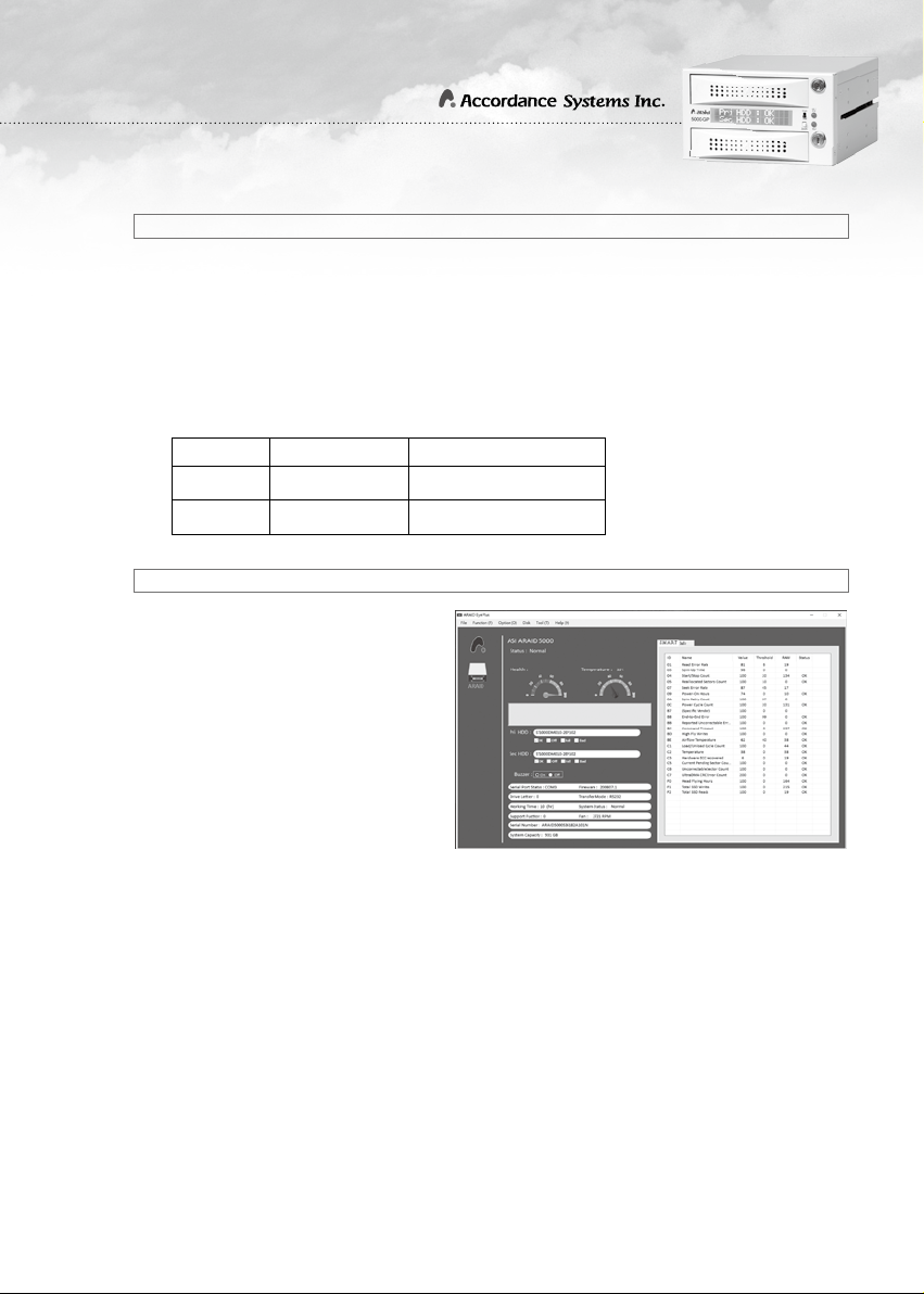
(1) It is suggested that same
type of new hard disk (same
brand, same model, same
capacity, same origin and
same firmware version) should
be used for working with this
product.You may use the
ARAID EYE PLUS software
included on the CD to check
the quality of the hard disks.
However, it is suggested that
you should prepare several of
the same and new hard disks
for backup. If the same hard disk is not available, you may use a larger-capacity
hard disk of the same brand.
Introduction of RAID 0 and RAID 1
Directions of Use
RAID Level Available Capacity Backup Hard Disk Function
0 16TB No
1 8TB Yes Table 1: RAID 0 vs RAID 1
Fig. 1: Checking the Hard Disk Quality with
ARAID EYE PLUS software

4
User's Manual
II. Product Content and Accessories
(1) Upon receiving, please check the items contained in the box. If any loss or
damage is found, contact your dealer or sales representative immediately.
(2) Optional Tray: If you want to use the same tray on both ARAID 5000 and ARAID
3500, please purchase this optional tray to use. Also refer below for the
installation of hard disk.
For ARAID 5000. Lock with hard disk
facing toward the FRONT END of the
tray.
For ARAID 3500. Lock with hard disk
facing toward the REAR END of the tray.
ARAID 5000 x 1 3.5” Hard Disk Tray x 2 Key for Tray x 4
M3x5mm Screw (for ARAID) x 8 M6x4mm Screw (for Tray) x 8
User’sManualx1
RS232 External Cable x 1 RS232 to USB Cable x 1
RS232 Internal Cable x 1
Management Programs CD x 1
Monitoring Program:
ARAID EYE PLUS
Network Management:
SNMP Agent for Windows
Firmware Upgrade Program:
Utility v0.50.9-5
Table 2: Product Content and Accessories
Fig. 2: Installing Hard Disk for the Optional Tray

5
III. Introduction of the Product
*
1. Product Features
Safety:
(1) When using RAID 1 mode, the content of both hard disks will maintain
synchronous status.
(2) A 6cm silent and cooling fan.
(3) Safety lock and key for the drive trays
(4) If ARAID uses with two hard disks, it can provide an off-line hard disk anti-virus
function under Single Disk Mode. (refer Page 18, Q2 of FAQ)
Convenience:
(1) When setting at RAID 0 Mode, it provides maximum drive performance.
(2) Supports most of the PC operating systems without the need of installing
additional drivers.
(3) Connects with SATA port of PC directly without going through a converter card.
(4) Support AHCI Mode and S.M.A.R.T.
(5) Works with most hard disk brands.
(6) Supports hard disk Hot-Swap and Hot-Plug.
Man-Machine Interface:
(1) The LCD displays system, hard disk, fan, and temperature status.
(2) The LED displays read/write activity.
(3) Includes an audible alarm (buzz) to alert of hard disk failure and abnormal status
of the fan and temperature.
Monitoring Interface:
(1) Provides real-time or simulated RS-232 port and dedicated communication
protocol through a connection with a COM or USB port.
(2) Provides SNMP function for standard network management support.

6
User's Manual
*
3. System Requirements
(1) Computer Interface: Connect the ARAID to a SATA III (6Gbps) port for maximum
performance. Backwards compatible with SATA II (3 Gbps) and SATA I (1.5
Gbps) ports.
(2) Hard Disk Interface: The SATA III (6Gbps) hard disk is suggested to demonstrate
the optimal efficiency. Backwards compatible with SATA II (3 Gbps) drives.
(3) Supported operating system (requires no additional drivers): Windows (XP only
supports AHCI Mode), Linux, SCO UNIX, FreeBSD, NetWare, Solaris, MAC OS
and QNX, etc.
*
2. Product Specifications
Table 3: ARAID 5000 Specifications
Dimensions 195mm (D) / 146mm (W) / 86mm (H)
Weight (w/o hard drives) Approx. 0.7kg
Temperature
Operating temperature: 0°C~65°C
Storage temperature: -20°C~70°C
Power Required +5V, +12V
Power Consumption Approx. 2.84W
(w/o hard disk)

7
Front View
1. LCD Display: Displays the information
relating to hard disk, fan and
temperature status.
2. Mode Selector Switch (Single/Dual):
Select Single or Dual mode.
3. Upper Hard Disk LED (HD1 R/W):
LED flashes when upper hard disk is
reading or writing the information.
4. Lower Hard Disk LED (HD2 R/W):
LED flashes when lower hard disk is
reading or writing the information.
5. Audible alarm (Buzzer On/Off): Press
this switch to temporarily disable the
alarm and press again to re-enable the
alarm.
Rear View and description
of Jumper settings
*
4. Description of Components
1 2
3
4
5
Front View
1 2 3
67
4
5
8
Fig3: Front View of ARAID 5000
Fig4:Rear View of ARAID 5000
1. 6cm silent and cooling fan.
2. UR1:RS232 port (for USB).
3. R1:RS232 port (for COM Port)
4. SATA III data connector:Connects to
the SATA port of the computer.
5. SATA power connector:Connects to
thecomputer’sSATApowersupply.
6. Jumper Setting:
7. Power Connector (4-pin power
connector):Connectstocomputer’s
4-pin power supply.
8. Fan Power Connector
Mode 0 1
RAID 0 Close Open
RAID 1 Open Close

8
User's Manual
*
1. Hardware installation
IV. ARAID Setup
(1) Disconnect the computer power source.
Connect the 3-pin RS232 Internal Cable to R1 of ARAID 5000 and attach to the
COM port of RS232 internal cable to the rear panel of the computer housing.
Next, connect the COM port and ARAID COM port of the computer with the
included RS232 External Cable.
1. If your computer has no RS-232 port, connect the 4-pin RS232 Internal Cable
to UR1 of ARAID 5000 and attach the COM port of the RS232 internal cable
to the rear panel of the computer housing. Next, connect the COM port and
ARAID COM port of the computer with RS232 to USB cable.
2. Install the provided USB-to-RS232 driver. After installing the provided driver
program, you may use the RS- 232 simulation function provided by USB Port
(normally set as following the COM3)
Caution: If your COM port is built-in to the motherboard, please
purchase your own COM port cable
(2) Connect with physical RS-232 Port:
(3) Connect the simulated RS-232 through a USB port
(ignore this step if you completed step 2 above.)
(4)SettheARAID5000intothecomputer’sopendrivebayswiththeprovided
screws and connect power cable and signal cable, and then replace the
computer cover.
Table 4: Hardware Installation Steps

9
Fig. 5: Hardware Installation Steps
SATA Cable(provide by user)
RS232 Internal Cable
Power Supply
ARAID 5000-GP
COM port
Mother Board
SATA port
USB port
ARAID 5000
RS232 External Cable
USB External Cable via RS232
4-pin power connector
0 1
SATA III
Power
UR1 R1
4
5
2
2
4
5
2
1-1/1-2
3-1/3-2
1-2 1-1
1-1
1-2
3-1
3-2

10
User's Manual
*
2. Starting and Operation (for RAID 1 Mode only)
Switch Mode
Single
Dual
Single
Dual
Single
Dual
Hard Disk
ARAID 5000
If the hard disk is inserted into the upper bay, the reading
If using one hard disk, the system can be started whether the
hard disk is inserted in upper bay or lower bay; however, it is
strongly suggested that you should set the hard disk at “Pri”
If the upper and lower bays are inserted with a hard disk, the
computer will execute the rebuilding function when shifting the
and writing can be
executed on the first
disk only.
position of upper bay
for using.
switch of the panel to
Dual Mode.
Even if the upper and lower bays are inserted with hard
disk, the reading and writing will be allowed on the upper-
bay disk only; at this time, the power of the lower-bay disk is
disconnected.
If the hard disk is inserted into the lower bay, the computer
cannot be started.
Warning: Do not remove the Primary disk before
completing the rebuilding of the hard disk to avoid
system failure, information loss or system garbling that
the computer cannot be restarted and even leading to
hard disk failure.
Single Dual

11
Switch Mode
Dual
Dual
Dual
Dual
Hard Disk
ARAID 5000
Rebuilding process (from upper bay to lower bay)
Rebuilding process (from lower bay to upper bay):
(1) Insert the hard disk into the upper bay to start the
computer.
(1) Insert the hard disk into the lower bay to start the
computer.
(2) The rebuilding function will be started after inserting the
Secondary HDD.
(2) The rebuilding function will be started after inserting the
Secondary HDD.
(3) Rebuilding
completed.
(3) Rebuilding
completed.
Placing two new hard disks that have never been used by
ARAID.
Caution: When operating under RAID 1 Mode and the switch is set at
“Dual” position, where two new hard disks never been used by ARAID are
inserted, it is required to run the Partition or the Format of the hard disk in
order to synchronize the content of these two hard disks. After that, it can
be used as the system disk or the data disk.
Caution: When using two hard disk, ARAID 5000 would start from the
Primary HDD as preset and the system would start with the Secondary
HDD unless the Primary HDD cannot be started.
Warning: When the switch is at “Dual” mode position and two hard disks
are processing rebuilding function, do not switch to Single position.
Otherwise, the power of Secondary HDD will be disconnected and cannot
execute the rebuilding in time. In this case, the system will execute the
reading and writing action on Primary HDD only.
Table 5: Starting and Operation

12
User's Manual
ARAID EYE PLUS is the management program allowing the user to monitor the
current health status of the hard disks (bad sectors) and to control the real-time status
of ARAID as well as to learn about the hard disk, and temperature related information.
If an error warning is displayed, it can also send out a notification through e-mail.
The “SNMP Agent” provides the enterprise-specific MIB, MIB II and Traps and it can
be run under Windows 2000 / Server 2003 / XP Pro. / Win 7 or later, or Redhat / SUSE
Linux. It allows the medium-large sized network administrator to manage dozens or
even thousands of ARAID disk arrays. It can also be used with HP OpenView, IBM
NetView and OpManager network software to do the central management in order to
control the hard disk, fan and temperature status for all arrays.
Fig. 6: ARAID EYE PLUS
Fig. 7: Network Management System
*
*
3. Local Monitoring
4. Network Management (Linux version is for optional purpose)

13
5. Checking for ARAID 5000 compatible drives
*
To check the suitable hard disks for ARAID, please visit our website as follows:
http://www.accordance.com.tw/web_search2/cus/index.php
※CompatibilitywithWesternDigitalharddisk:
・If selecting Western Digital drives, we suggest that the customer should use the WD
Enterprise class or RAID series and specifically not use the Caviar series (Blue/
Green/Black label).
・Western Digital warns against using Caviar series drives in a RAID array.
(http://wdc.custhelp.com/app/answers/detail/a_id/1397)

14
User's Manual
1. Power ON/OFF switch.
2. AC110~220V power socket.
3. RS232 Connector (COM port)
*
1. Description of Component
Product specifications
V. ARAID T5000 (External model)
Fig. 8: Front View and Rear View of ARAID T5000
Table 6: Specifications of ARAID T5000
Dimensions 240mm (D) /183.2mm (W)/156.15mm (H)
Weight (w/o hard disk) Approx. 2.68 kg.
Power Supply Unit 63W Standalone PSU
Power Consumption (w/o hard disk) Approx. 5.14W~7.32W
(varied depending on the model)

15
Table7: Types of ARAID T5000 External Model
2. Types (Host Interface) of ARAID T5000
*
Type of Interface Cable Description
1. SATA connector

16
User's Manual
Both hard disks are running normally.
Upper bay hard disk is normal,
but lower bay hard disk is failed or
abnormal.
Lower bay hard disk is normal, but
upper bay hard disk is failed or
abnormal.
Upper bay and lower bay hard disks
are faulty or abnormal.
Fan is abnormal
Overheat warning
(preset value is 65°C / 149°F)
The capacity of the Target HDD is less
than the Source HDD
The capacity of the Target HDD is less
than the Source HDD
Source HDD failed during automatic
rebuilding.
Source HDD failed during automatic
rebuilding.
Both hard disks are used as Source
HDD in ARAID.
Both hard disks are used as Target
HDD in ARAID.
Replace lower bay hard
disk.
Replace upper bay hard
disk.
Replace both hard disks.
Check if the fan power plug
is loose.
Check if the fan is working
normally and if the storage
temperature is over 65°C.
Replace the Target HDD
with a drive of capacity not
less than Source HDD.
Replace the Target HDD
and its capacity shall not
be less than Source HDD.
Replace it with a healthy
Source HDD.
Replace it with a healthy
Source HDD.
Insert the designated
Source HDD to start the
computer. If starting is
succeed, insert Target
HDD.
Insert the designated
Source HDD to start the
computer. If starting is
succeed, insert Target
HDD.
VI. ARAID LCD Message Comparison Table
(for RAID 1 User)
StatusStatus DescriptionDescription ActionAction

17
RAID configuration of the two hard
disks do not match.
Hard disks undetected.
Unable to find RAID configuration
information in hard disks.
Insert the designated
Source HDD and start the
computer. Once the startup
is successfully completed,
insert the Target HDD.
Check if the inserted hard
disks are functioning
normally. Then, re-insert
the designated Source
HDD and start the
computer. Once the startup
is successfully completed,
insert the Target HDD.
Insert the designated
Source HDD and start the
computer. Once the startup
is successfully completed,
insert the Target HDD.
Status Description Action
Table8 : ARAID LCD Message Comparison Table
※ Iftheharddiskfailsduringtherebuild,ARAID5000willskipthebadsectorsandthen
complete the rebuild.
※ DonotusetheharddiskwhichhasbeendeterminedfailedbyARAID5000,otherwiseit
may lead to system damage.
※ ThemeaningofLCDDisplay:Pri = Upper bay ; Sec = Lower bay.

18
User's Manual
VII. FAQ (for RAID 1 Users)
1. Power failure while hard disk rebuilding is in progress
Q:
A:
WhatshouldIdoifthepowerfailswhileauto-rebuildisinprogressandIdon’thave
UPS equipment?
Simply turn on the computer again and the Automatic Reset Function (ARF) will
continue the rebuilding progress from the interrupted point by itself. Whether
rebuilding progress was from Pri. to Sec. (upper bay to lower bay) or from Sec. to
Pri. (lower bay to upper bay), when resuming the power, the computer will boot
from the source drive by itself and continue the rebuilding automatically (in this
case, the Panel Switch should be continue to be set at “Dual Mode”).
2. Using ARAID-specific Mirror-On-Demand anti-virus function.
3. Replacement or upgrading of hard disks.
Q:
A:
Q:
A:
How to prevent the hard disk from getting infected by a virus?
(1) If one of the hard disks in the ARAID is infected, both of them will be infected
at the same time. Therefore, ARAID has been specially designed to set single disk
operation directly on the front panel in order to the limit reading and writing on the
computer to a single hard disk. After confirming the input data is accurate, the user
can proceed the rebuilding steps for achieving synchronized content of both hard
disks.
(2) Through our experiences in dealing business with customers in Japan, Taiwan
Power Plant Company, Chunghwa Telecom and Taiwan Philips as well as that
possessed by our MIS personnel, to accomplish the optimal anti-virus effect, it is
strongly suggested that the user should purchase one to several trays and several
hard disks for doing the off-line backup regularly. In the event the hard disk is
infected, the user may select a suitable backup hard disk and restart the uninfected
system and information within the shortest period of time (i.e. executing the father-
son-grandson multi-generation rebuilding function described in our catalogue).
What is the procedure when a hard drive fails?
(1) If you need to replace the hard disk or pull out the disk for other reasons, to
protect the completeness of the data, please pull out the hard disk after shutting
down the equipment as much as possible. If it is not allowed to shut down the
equipment, execute such work during the period when the ARAID reading and
writing is least frequent (when the LED indicator is not flashing). Because if you
pull out the hard disk without shutting down the equipment, the correction message
mayappearunderWindowswhenusingsuchharddisklateron;further,there’sa
risk that the data contains in the hard disk may get lost once you decide to execute
the correction.
This manual suits for next models
1
Table of contents
Languages:
Other Accordance Systems Storage manuals
Popular Storage manuals by other brands

Western Digital
Western Digital WD Dual-option user manual

Synology
Synology Disk Station DS1010+ Hardware installation guide

Addonics Technologies
Addonics Technologies CRC4HESU manual

Quantum
Quantum StorNext M660 Hardware guide

HP
HP StorageWorks 1000 - Modular Smart Array specification

Seagate
Seagate Backup Plus Desktop user guide