6
User's Manual
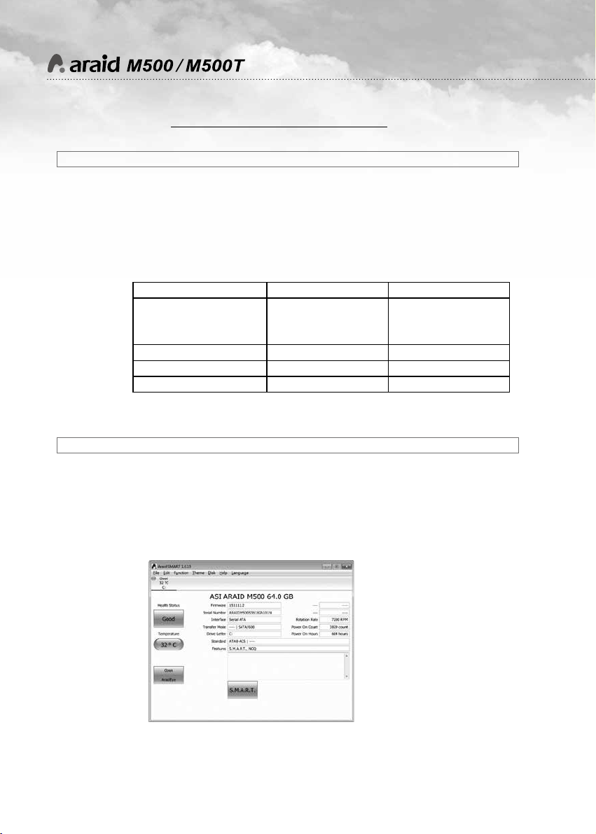
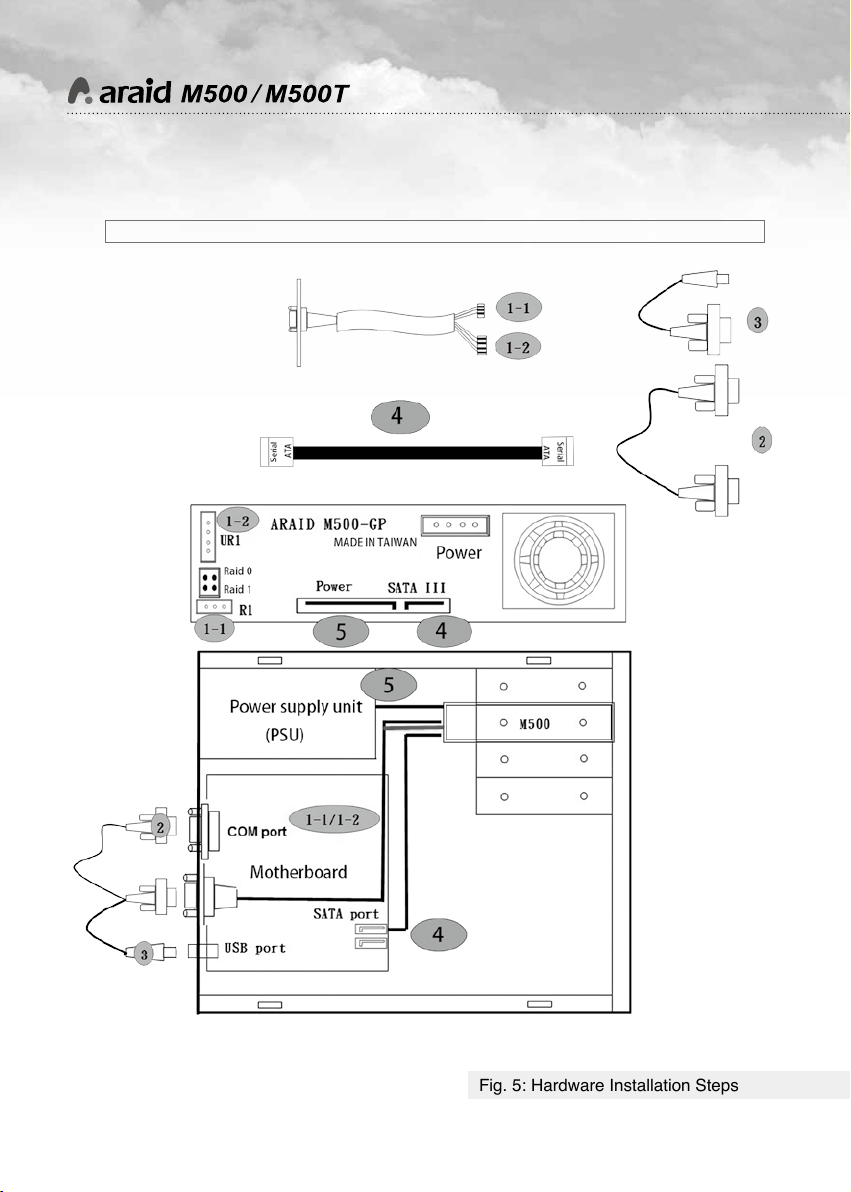
(1) Computer Interface: Connect the ARAID to a SATA III (6Gbps) port for maximum
performance.
(2) Hard Disk Interface: The 2.5” SATA III (6Gbps) hard disk or SSD is suggested to
demonstrate the optimal efficiency.
(3) Supported operating system (requires no additional drivers): Windows, DOS,
Linux, SCO UNIX, FreeBSD, NetWare, Solaris, MAC OS, IBM OS/2, and QNX, etc.
*
System Requirements
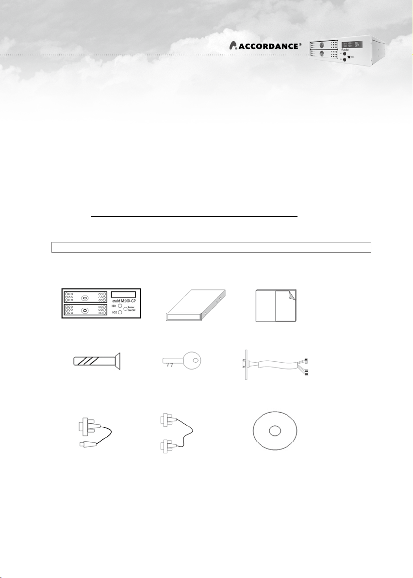
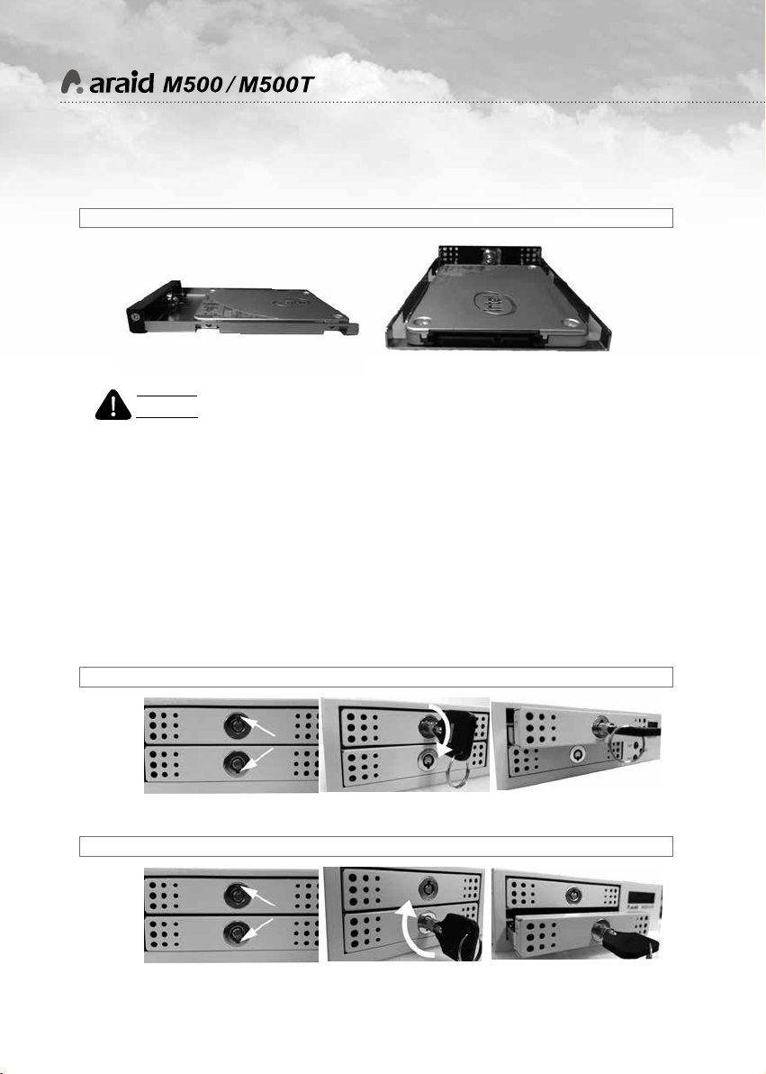
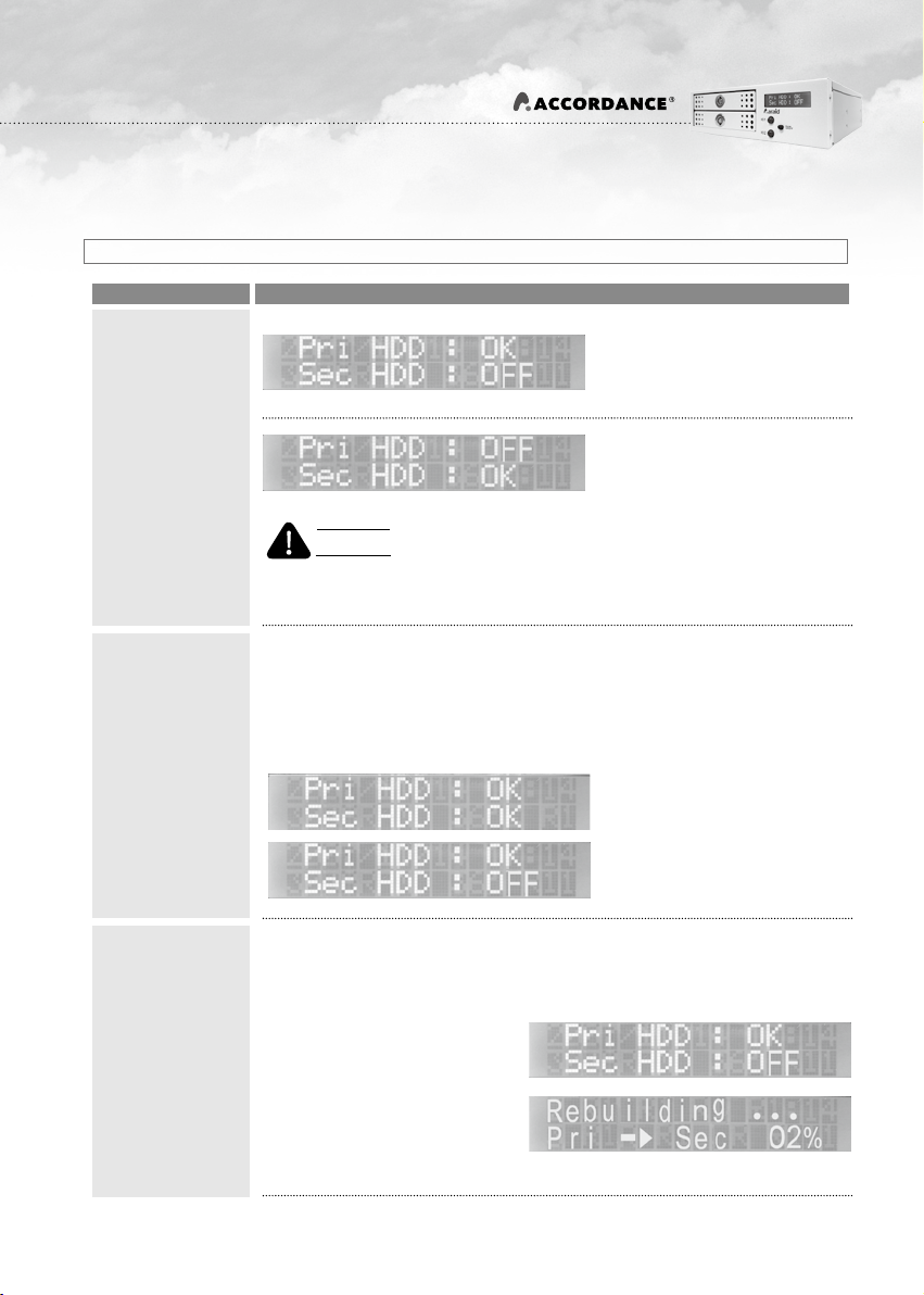
1.LCD Display:
Displays the information relating to hard
disk, fan and temperature status.
2.Audible alarm (Buzzer On/Off):
Press this switch to temporarily disable
the buzzer, press again to re-enable the
buzzer.
3.HD1 LED Read/Write indicator:
LED flashes when upper hard disk is
reading or writing the information.
4.HD2 LED Read/Write indicator:
LED flashes when lower hard disk is
reading or writing the information.
1. 4m Japan-made silent and powerful cooling fan.
2.Power connector (4-pin power connector):
Connects to computer’s 4-pin power supply.
3.SATA III data connector:
Connects to the SATA port of the computer.
4.SATA power connector
Connects to the computer’s SATA power
supply.
5. R1: RS232 port (for COM Port)
*
Description of Components
6. Jumper settings
7. UR1: RS232 port (for USB).
1234 2347 56 1
Fig. 3: Front View of ARAID M500 Fig. 4: Rear View and Jumper Setting of ARAID M500
RAID 1
(Default)
RAID 0