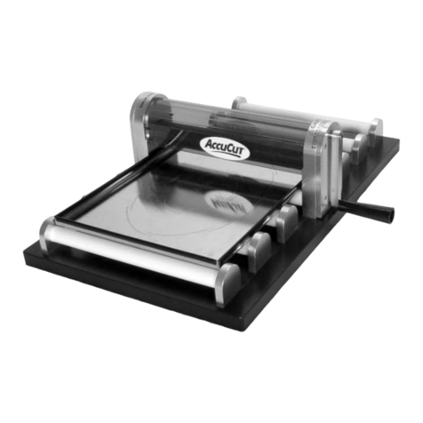
Accu-Cut IVC 15 User manual

1
OPERATOR’SMANUAL
ACCU!
!!
!CUT®IVC 15
Carpet & Vinyl Cutting and Rolling Machine
Brockie International Inc. 305A North Highway 27, Clermont, Florida 34711 USA
Phone: 800-527-7057 or 352-242-0400 Fax: 352-394-1449
E-mail: info@accu-cut.com • Website: www.accu-cut.com
For Parts or Service contact
ACCU!
!!
!CUT®Support 1800-527-7057
Manual Part Number: 8-0030-D02

2
INTRODUCTION..................................................................... 4
SAFETY PRECAUTIONS....................................................... 5
DEFINITIONS ......................................................................... 6
ABOUT THE MACHINE.......................................................... 7
OPERATING PROCEDURES................................................. 8
•Procedures for cutting
Loading the material----------------------------------8
Adjusting the shuttle cradle-------------------------8
Adjusting the size of the load cradle--------------8
Unwrapping new & tightening loose rolls --------9
Positioning the material------------------------------9
Entering the cut length-------------------------------10
Setting the speed control----------------------------10
Rolling up the material -------------------------------11
Monitoring the roll -------------------------------------11
Cutting the material-----------------------------------12
Sharpening the blade---------------------------------12
Wrapping the cut length -----------------------------12
Dumping the cut length ------------------------------13
Dumping material in the load cradle--------------13
•Measuring roll balances
Loading the material----------------------------------13
Programming the counter ---------------------------13
•Procedures for reverse rolling
Rolling up the material -------------------------------14
A few words about reverse rolling-----------------14
•ACCU
!
!!
!
CUTÆOptions
Pinch roller----------------------------------------------15
Top counter---------------------------------------------16
Manual wrapping dispenser-------------------------16
CONTENTS

om-1500-02-010506 Page 3of 37
PLC
COUNTER
FE
A
TURES
A
ND
OPTIONS
........................
17
•
Custom
izi
ng
Sett
i
ngs
Accessing the master menu
------------------------
17
Changing the password------------------------------
17
Changing the timer------------------------------------
18
Eliminating the timer
----------------------------------
18
Changing the cutter (blade reminder)
------------
18
•
PresetMeasurements
Storing a preset measurement
---------------------
19
Se
l
e
ct
i
ng a
st
o
r
ed p
r
e
s
et
m
ea
s
u
r
e
m
en
t
---------
1
9
SET UP INSTRUCTIONS
.......................................................
22
TROUBLE SHOOTING...........................................................
23
PARTS DIAGRAMS
................................................................
25
ELECTRICALDIAGRAM
.......................................................
36
LIMITATION OF LIABILITY.....................................................37

4
Congratulations on the purchase of your ACCU!
!!
!CUT®IVC15 carpet and
vinyl cutting and rolling machine. Your ACCU!
!!
!CUT®machine has been
carefully engineered and manufactured to provide you with many years of
dependable service and trouble free operation.
Proper operation and maintenance is essential to ensure precise and de-
pendable operation of your ACCU!
!!
!CUT®. We encourage you and your
employees to read this manual carefully and become familiar with the op-
erating and maintenance procedures for this machine.
This manual is designed to cover all areas of operation, maintenance, and
troubleshooting in order to minimize problems. Always follow all safety
rules and precautions when operating or performing maintenance work on
the machine.
Again, congratulations and thank you for choosing Brockie International
to provide you with quality equipment and quality service. The confidence
you and hundreds of others have placed in us has helped to make
ACCU!
!!
!CUT®and Brockie International two of the most respected names
in floor covering cutting and merchandising equipment. Should you ever
have any questions or concerns regarding your ACCU!
!!
!CUT®please do
not hesitate to contact us.
BROCKIE INTERNATIONAL, INC.
INTRODUCTION

5
SAFETY PRECAUTIONS
In order to avoid personal injury, make sure the operator(s) and/or mainte-
nance person(s) of the machine have been oriented with the machine’s op-
erating procedures and are aware of all safety precautions.
1. Unplug power cord before making any adjustments or re-
pairs.
2. A qualified electrician should perform electrical repairs.
3. Do not operate machine on a wet floor.
4. Use extreme caution when replacing cutter blades.
5. Keep hands clear of all moving components while machine is
running.
6. Keep loose clothing and articles away from all moving com-
ponents while machine is running.
7. Keep machine unplugged while not in use.
8. Do not allow children near the machine.
9. Keep machine clean of all plastic wrap, carpet fibers, and all
other debris.
10.Ensure machine is stationary and will not roll on casters.
11.Stay clear of moving load side shuttle cradle.
12.Do not remove chain covers except for servicing.
13.Keep space beside cradles (dumping areas ) clear.

6
DEFINITIONS
ACCU-CUT: Trade name of equipment you have purchased.
LOAD SIDE CRADLE: Refers to the roller carriage located on the side of the machine where the
operator places the full or partial roll of flooring.
ROLL UP CRADLE: Refers to the roller cradle located on the opposite side to the Load Side Cra-
dle which rolls up the flooring.
CONTROL PANEL: The area where your equipment is operated. This panel houses the direc-
tional controls, variable speed control, and the programmable logic control display.
PROGRAMMABLE LOGIC CONTROL: (PLC) display. This display has the foot and inch counter,
shuttle cradle control as well as other advanced controls.
INSPECTION TABLE: Area used by the operator to visually inspect the goods being measured
and cut for the customer.
HOLD DOWN ARM: This is the arm that holds flooring firmly on counting wheel.
MEASURING WHEEL: This device is connected to the advanced encoder that emits 600 pulses
per revolution.
ACCU!
!!
!CUT®IVC 15 Inspection Table
Load Shuttle Cradle
Measuring Wheel
Cutter Hold Down
Load Side Dumping
Dump Safety
Latch
Control Panel
Cutter Safety Bar
Roll Up Cradle
Foot Cable
Roll Up Arm
Roll Up Side Dumping
Mechanism
Adjustable Leg

7
ABOUT THE MACHINE
The ACCU!
!!
!CUT®IVC15 cut and roll machine consists of two sets of steel rollers that are referred to as
cradles. The side where material is loaded is the load side cradle, while the opposite side is the roll up
cradle.The roll up cradle is designed to run slightly faster than the load side to ensure a tight roll up of
material. Each cradle is chain driven by heavy duty UL & CSA approved electric motors.
The IVC15 is operated from the control panel, which includes the directional controls, variable speed
control and the Programmable Logic Control or PLC Interface display which houses the foot & inch
counter, shuttle cradle control as well as other advanced controls.
The ACCU!
!!
!CUT®IVC15 measuring system is extremely accurate. It consists of a large diameter,
knurled measuring wheel located in a cutout of the inspection table below the hold down arm.The
measuring wheel is connected to an advanced encoder that emits 600 pulses per revolution. The en-
coder communicates with the foot & inch counter in the PLC to provide you with an accurate measure-
ment.
The cutter assembly on the IVC15 consists of 5 1/2” or 4 1/2” circular blade positioned within a cutter as-
sembly inside the cutting track. The IVC15 also has a cutter bar that not only covers the blade while
making a cut but also holds the material tight. The cutter assembly is chain driven by a dedicated cutter
motor. (The 4 1/2” circular blade is used primarily for commercial vinyl.)
The circular blade is self sharpening.
(see sharpening blade on page 10 for details)
A wrap around foot control cable is provided to operate the machine “hands free” while inspecting
wrapping, unwrapping, or tending the roll. It can be set to be on only when you step on the foot cable or
as a toggle. So the machine stays in an on position.
The IVC 15 also includes a dumping mechanism on both the load side cradle and roll up cradle that
will quickly and simply offload the material onto the floor allowing another roll to be loaded without remov-
ing the goods with a forklift. The load side dumping mechanism is particularly useful when used in con-
junction with a feed table.

8
OPERATING PROCEDURES
PROCEDURES FOR UNROLLING AND CUTTING
Loading the material
Place the material on the shuttle load cradle, making sure the lead-
ing edge of the material is feeding across the inspection table from
the bottom of the roll with the pile side up and the backing
down – vinyl can be measured pattern up or down. Place the roll in
the cradle with the end of the roll just past the last belt on the front
end of the cradle
Roll-Improver
This feature is useful to position the roll in the load
cradle, as well as squaring the leading edge to the
cutting line. In normal operations make sure the roll
improver is down at both ends while roll is rotating. By
moving either end of the roll improver up and squeez-
ing the roll at the same time you can cause the roll to
walk to the front or back of the load cradle, when the
roll is positioned ensure that both ends of the roll im-
prover are down. When the leading edge of the mate-
rial is off square you may adjust this by activating the
roll improver as well as the amount of squeeze on the
roll in the load cradle. Make sure that the roll improver
is back in the lower position after material has trav-
eled several feet
Adjusting the size of the load cradle
The size of the load cradle can be adjusted by moving the load side dumping mechanism and altering
the position of the outside roller. Adjusting the size of this cradle to a size consistent with the diameter of
the material provides the operator with greater control over the material, by squeezing the roll it keeps the
roll squared to the cradle.
Adjusting the shuttle cradle
The IVC 15 is equipped with a shuttle cradle that can be used to properly line up the material on inspec-
tion table. The edge of the material should be within a few inches of the bumper at the front of the inspec-
tion table. Adjusted by arrows ( Photo 1B ) buttons on PLC.
Photo 1A
Photo 1B
Photo 1C
Shuttle Cradle Forward Position Photo 1D
Shuttle Cradle Back Position

9
Unwrapping new rolls and tightening loose rolls
After loading the wrapped roll, cut the plastic the full length of the roll and at each end. Position the load
cradle roller directional switch in the reverse position, and then step on the foot cable control while
pulling off the plastic wrapping.
If you have a loose roll, run the load cradle rollers in reverse by placing the load cradle roller directional
switch in the reverse position and pressing the jog button or stepping on the foot cable control to acti-
vate the load cradle rollers. Continue to run the rollers in reverse until the roll has tightened.
Positioning the material
Raise the hold down arm, lifting it off the measuring wheel. Set both roller directional switches to for-
ward. Step on the foot cable control or press the jog button, advancing the material to the center of the
cutting track (see photo 3A). Now lower the hold down arm back on to the measuring wheel. Failure
to lower the hold down arm will result in an inaccurate measurement.
Note:If the material is off square, line the trailing edge of the material with the
cutting track (see photo 3B).
Photo 3A Photo 3B

10
Setting the speed control
The speed at which the rollers turn can be quickly and simply adjusted
by turning the variable speed control knob located on the control
panel. It is recommended keeping the speed at a low setting when
beginning the roll up process and increasing the speed as the roll in-
creases in size.
Entering the cut length
With the material lined up in the center of the cutting track the counter must now be reset to zero by
pressing “ Count Clear” button on PLC it can now also be programmed with the desired cut length.
To enter your desired cut length:
♦Press clear to erase the previous measurement – in this example the previous meas-
urement was 18’ 6” (see photo 4A)
♦Enter the number of feet & inches to be cut – in this example 12’ (see photo 4B) –
Press enter
♦If 12 ft. 8 inches enter 1208 if 12 ft. 11 inches enter 1211
The desired cut length is now entered into the counter and the roll up process can begin.
Photo 5
Photo 4A Photo 4B
Photo 4C
Note: ENSURE THAT CARPET 1 IS SELECTED. This will be indicated in the display
by “CARPET 1” Failure to have carpet 1 selected could result in inaccurate
measurements.

11
Rolling up the material
Now that the counter is set to zero (0) advance the leading edge of the material just past the center of the
2nd. big roller on the roll up cradle, (see photo 8A) (if using a paper core, place it on top of the material in
the cradle now). Now close up roll-up arm (see photo 8B).
Warning: Keep hands clear of the roll-up arm.
Advance the material till the desired length.
NOTE: After the material has made several revolutions open roll-up arm (see photo 8C)
(If roll-up arm is not opened early enough the material may pile up on the inspection table).
Keep pressure on the roll to ensure a tight roll (see photo 8D).
(You may also tighten the roll by continuing to rotate it after the cut).
Should the roll need to be adjusted in the cradle, open roll-up arms and adjust by hand.
Photo 8A Photo 8A
Photo 8C Photo 8D

12
Cutting the material
When there is less than one foot remaining to be measured the machine will automatically slow down and
stop precisely at the programmed length. Before activating the cutter ensure the length of cut that the
counter registers is the desired length and if it is not jog the material accordingly; now lower cutter safety
bar and turn cutter switch knob in the direction the cutter needs to travel. Release knob when cutter
reaches the end.
Note: When processing 15’ wide material the cutter should be stored at the control panel end of the
machine. If the cutter is left at the far end of the machine it may interfere with the material as it
moves across the inspection table.
Sharpening the blade
The cutting system on the IVC 15 is equipped with a self-sharpening mechanism – it is not necessary to
remove the blade for sharpening. When the blade reaches the front end of the machine a “clutch” en-
gages leaving the blade stationary while rotating against the sharpening mechanism. To sharpen the
blade simply keep the cutter engaged when it reaches the end of the cutting track. It is recommended
that the blade be sharpened for 7 to 10 seconds after every 50 cuts.
Wrapping the cut length
To wrap the cut length, keep the roll-up cradle roller directional switch in the forward position and place
the load cradle roller directional switch in the off position. Place the wrapping material inside the flap of
the material you are wrapping. Stepping on the foot cable control will rotate the roll, letting you wrap the
material while it is still on the machine.
Caution: Keep hands and all loose clothing away from moving parts.
Photo 11A Photo 11B Photo 11C

13
MEASURING ROLL BALANCES
To determine the balance remaining on a roll or to check the length of a new roll perform the following
procedures:
♦Program the counter:
1. Press clear
2. Enter a large number i.e. 5000’ – since the length of
the roll is unknown it is necessary to enter a number
much larger than the estimated length of the roll
3. Press enter
♦Line up the edge of the material to be measured to the cen-
ter of the measuring wheel pile side up. (see photo 13)
♦Press clear count to reset the counter to zero
♦Follow the procedures for “Rolling up the material” detailed
on page 9
♦Continue rolling up the material until the final few feet of the
roll is reached. At this point slow down the speed of the rollers using the variable speed
control knob and continue advancing the material until it is centered with the measuring
wheel.
♦The measurement indicated on the counter is the length of the material.
♦Note: Failure to slow down the rollers at the end of the measurement may result in the
measuring wheel continuing to turn and measure even after the trailing edge of the material
has passed the wheel. This will result in an inaccurate measurement.
Dumping the cut length
The cut length can be dumped on to the floor by opening the roll-up arm fully.
To assist the dumping process jog the roll-up cradle forward.
Caution: Make sure the area is clear before dumping the cut length.
Dumping the material in the load cradle
The material in the load cradle can be dumped on to the floor by releasing the dump safety latch
( Pull latch towards you) and at the same time open load cradle fully. To assist the dumping process jog
the roll-up cradle in reverse.
Caution:Make sure the area is clear before dumping the cut length.
Photo 12A Photo 12B Photo 12C
Photo 13

14
PROCEDURES FOR REVERSE ROLLING
Reverse rolling is an effective manner of merchandising remnants. Several dealers even merchandise
full rolls pile side out. An optional top counter and pinch roller may be necessary for reverse rolling full
rolls.
The procedures for reverse rolling are identical to the procedures for “Measuring roll
balances” (page 13) with the following exceptions:
Rolling up the material
After setting the counter, either press the jog button or step on the foot cable control. Place the paper
tube in the roll-up cradle and advance the leading edge of the material until it reaches the second. big
roller on the roll-up cradle (see photo 14A). Position the material on top of the tube.
Leave the load cradle roller directional switch in the forward position but place the roll-up cradle roller
directional switch in the reverse position.
Close the roll-up arm and engage the rollers by stepping on the foot cable control or pressing the jog
button. The roll-up arm will cause the material to begin rolling in reverse around the cardboard tube and
start the roll-up procedure. (see photo 14B). After the material has made several revolutions open the roll-
up arm. (see photo 14C).
NOTE: If the material is walking up on the inspection table momentarily shut off the roll-up cradle to allow
load cradle to catch up.
A FEW WORDS ABOUT REVERSE ROLLING
Reverse rolling is a simple process but often takes time to perfect and learn – be patient. There are nu-
merous times when and how reverse rolling can occur. We have tried to list the most common below.
Reverse rolling the balance of a roll after making a cut:
After removing the cut length from the roll-up cradle, reverse the material in the load cradle so that the leading edge
is centered with the measuring wheel. Reset the counter to zero then follow the steps at the top of the page. The
measurement indicated on the counter is the length of the material.
Reverse rolling with the material coming off the top of the roll and pile side down:
If the length of a roll is already known, some operators will choose to reverse roll the material having the material
feed from the top of the roll with pile side down. This method allows the operator to keep roll-up cradles in the for-
ward position, load side reverse and use the roll-up arm in the same manner as when making a cut. Please note that
it is not possible to get an accurate measurement with the pile side down.
Photo 14A Photo 14CPhoto 14B

15
ACCU!
!!
!CUT®OPTIONS
PINCH ROLLER
This optional attachment was designed to assist dealers who like to reverse roll full rolls of carpet pile side
out for display – i.e. GCO Carpet Outlets.
NOTE: This is not a IVC15 however the Pinch Roller is the same!!
The purpose of the pinch roller is to keep the carpet close to the inspection table thus keeping the coun-
ter hold down from raising while running carpet through the machine. In order to reverse roll a full roll
the flap must be coming off of the top of the roll. If this is attempted without a pinch roller on a large roll
the material will cause the counter hold down to raise off the measuring wheel making it impossible to
reverse roll and measure at the same time.
Pinch Roller Reverse Roll Pile
Pinch Roller Lowered Pinch Roller Raised

16
TOP COUNTER
The top counter allows material to be run across the inspection ta-
ble pile side down and still receive an accurate measurement. The
top counter, consisting of two measuring wheels and a digital coun-
ter, is designed to be used in conjunction with a pinch roller provid-
ing a manner in which full rolls of carpet can be reverse rolled pile
side out and measured at the same time.
The top counter is attached directly to the hold down arm. Measure-
ments are made with top counter in the same manner as the stan-
dard counter except when measuring a roll balance, line the leading
edge of the material up with the center of the top counter wheels –
not the measuring wheel in the inspection table.
Note: The top counter uses a decimal type measurement and a conversion
table must be used to convert the measurement to feet and inches.
MANUAL WRAPPING DISPENSER
Stretch wrap will always be within arms reach with a manual wrapping dispenser. To wrap the cut length,
keep the roll-up cradle roller directional switch in the forward position and place the load cradle roller
directional switch in the off position. Place the wrapping material inside the flap of the material you are
wrapping. Stepping on the foot cable control will rotate the roll, letting you wrap the material while it is
still on the machine. Simply pull the dispenser assembly along as the roll wraps itself.
Photo 16A Photo 16B
Wheeled Dispenser Base
Track

17
COUNTER OPERATING INSTRUCTIONS Ver. 2.02
Congratulations on your purchase from Brockie International / Vidir Machine Inc. This machine is
equipped with an advanced 16-bit microprocessor PLC unit to ensure accurate measurement. To com-
municate with this PLC we have provided a user-friendly interface. Simply enter your commands into the
keypad and watch the machine do the work for you.
Keypad Familiarization
Grey keys- Data entry / Presets / Product
Yellow key- Auto run
Blue key- Carriage control
Red keys- Cutter and cutter safety
Green key- Clears measured length
Password Protection
This unit is equipped with a “Password Protection” feature. Every time the machine is turned off or is un-
used for a designated time the machine prompts the user to
“ENTER PASSWORD”
****
To enter the password: 1. Press CLEAR to remove asterisks
2. Type in the four digit security code (Factory preset is “4321”)
3. Press ENTER
You have now gained access to the machine and may begin to roll, measure and cut the product.
Setting Preset Length
This unit is equipped with a multi-preset feature that enables the user to enter the required length of mate-
rial into the machine’s memory. This will prompt the machine to automatically slow down the rolling proc-
ess approximately one foot before the desired length has been reached. It then slowly rolls to the preset
length.
To enter a preset length: 1. Press CLEAR to erase the previous measurement
2. Type in the desired amount of feet & inches
(last 2 digits are inches if imperial or centimeters if metric)
3. Press ENTER
Your desired length is now entered into the counter. You are now ready to roll and cut the product.

18
Multi-Cutting
This unit is equipped with nine pre-programmable lengths. You now have your first preset selected. To
change to another preset press SCROLL PRESET up or down. This will change your preprogrammed
length. Press clear to change the pre-programmed length. . To program all 9 presets simply repeat the
procedure described in “Setting Preset Length”. Once you have completed this, the lengths are stored in
the memory of the machine and remain present even when the machine is unplugged. This feature is
very useful when cutting a series of same size pieces for a given house plan for example.
Rolling the Product
1. Bring carpet to the center of the cutting bar.
2. Verify that your desired carpet length is in the display
3. Press CLEAR COUNT to clear the counter
4. Advance the carpet to the middle of second roller on IVC 15
5. Lift the roll-up cradle
6. Run the machine until it stops
7. Verify the count (reverse direction if necessary)
Cutting the Carpet
Now that you have accurately measured the carpet you are ready to proceed with a cut. Turning the cut-
ter switch with the cutting bar down controls the bi-directional cutter. A beep provides the user with a
warning that cut is being performed. The counter also keeps track of the number of cuts the machine has
made. This is helpful to help gauge your blade life expectancy.
CUTTER and cutting bar down: CUTTING CARPET NOW
(CUT #)
Carriage Control
Your machine is equipped with a movable carriage which may be adjusted through the interface
When CARRIAGE is pressed and the machine’s carriage travels away from the operator.
When CARRIAGE is pressed and the machine’s carriage travels towards the operator.
Multiple Scale Factors
Sometimes different products grip the count wheel differently due to their adhesive nature. We have
taken this into consideration by allowing this machine to retain six separate scale factors to accommodate
a variety of materials. Differently product may be selected at any time by pressing SCROLL PRODUCT.
This changes the screen to display another product.
Examples of different presets measuring differently:

19
IMPERIAL METRIC
Scroll product once: CUT 1 0’ 0” CUT 1 0 CM
CARPET 120’ 0” CARPET 1 608 CM
Scroll product twice: CUT 1 0’ 0” CUT 1 0 CM
CARPET 19’ 10” CARPET 2 603 CM
Scroll product thrice: CUT 1 0’ 0” CUT 1 0 CM
CARPET 3 20’ 1” CARPET 3 611 CM
(etc…)
The user is responsible to verify the accuracy of the count for the product sold and to arrange required
certification. The manufacturer or its agents cannot be held responsible for any inaccuracies in cut
lengths.
Master User’s Menu
This counter may be tailored to better suit the user of the machine. When 3 fingers are depressed on the
logo a MASTER PASSWORD is brought up.
MASTER PASSWORD
*****
To enter the master password 1. Press CLEAR to remove asterisks
2. Type in the 4 digit master password
3. Press ENTER
Upon entering the correct password you now have gained access to the Master Users Menu.
The word menu will then appear followed by a scrolling line below it:
MENU
1 CHANGE PASSWORD 2 CHANGE TIMER 3 CHANGE BLADE 4 METRIC/IMP
5 SLOW DOWN 6 CALIBRATION 7 FS AUTO RUN
The user selects one of the options by pressing 1, 2, 3, 4, 5, 6, or 7 and now has gained access to their
desired feature.
Changing the Password
The four-digit security code is changeable for your convenience.
To change the code: 1. Access the master menu as described above
2. Press 1
The following then appears: ENTER NEW PASSWORD
****
To enter a new password: 1. Press CLEAR to remove asterisks
2. Type in a new password
3. Press ENTER
Changing the Password Timer

20
When the unit is left idle for a period of time, the user is locked out. However, that period of time may be
varied by the user for up to 999 seconds. If 0 is entered, the password timer and password is disabled.
To change timer: 1. Access the master user menu as described earlier
2. Press 2
The following screen now appears: NEW PASSWORD TIMER
# SECONDS
To change the timer value: 1. Press CLEAR to remove old timer value
2. Type in the desired time in seconds
3. Press ENTER
You have now changed the length of time the machine requires before it turns itself off without input.
Factory preset is 120 seconds. If the machine will be located in a publicly accessible location we recom-
mend a time of 15 seconds. The operator should never leave the machine unattended while the pass-
word is active and the cutting blade is in the garage. The manufacturer or its agents cannot be held re-
sponsible for any injuries to anyone of any kind howsoever caused. The operator is solely responsible for
safe operations and mechanical and electrical condition of the machine at all times.
Metric/Imperial Measurement
This counter is able to measure in feet and inches as well as centimeters. It may be used in imperial
mode, metric mode, or be switched between the two at the press of a button.
To change measurement mode: 1. Access the master menu
2. Press 4
The following then appears: 1 IMPERIAL 2 METRIC
Press the number of the desired mode in which you wish to count in.
Slowdown
The user is now able to determine how many inches before completion the carpet cutting machine enters
its slow down mode.
To access slow down: 1. Access the master menu
2. Press 5
The following then appears: SLOW DONE _ _”
BEFORE STOPPING
To change the length: 1. Press CLEAR
2. Type in the desired length in inches
3. Press ENTER
Your machine will now slow down your entered amount of inches before stopping.
Calibrating the Machine
The calibration of all 6 scale factors of this machine may be changed using the master menu.
Table of contents
Other Accu-Cut Cutter manuals