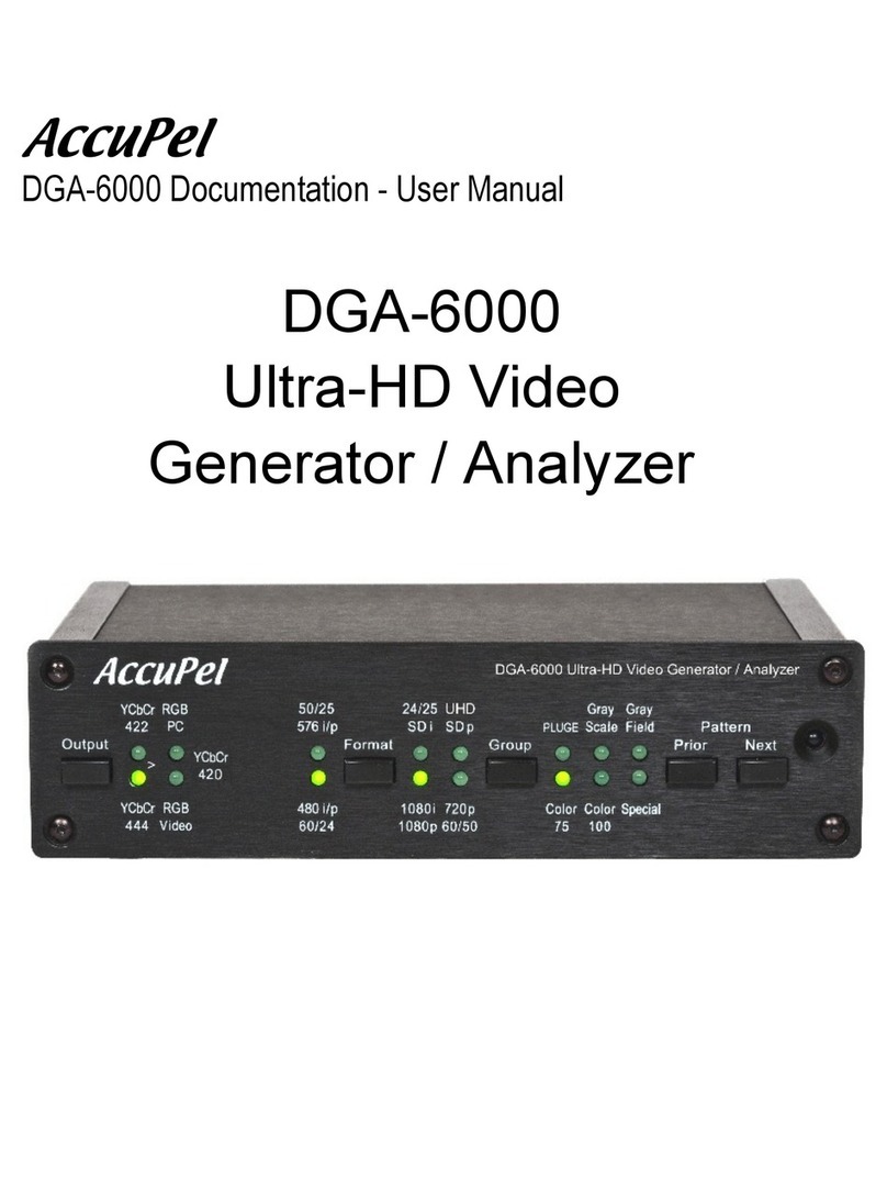
AccuPel HDG-4000 User manual

HDG-4000 ANALOG/DIGITAL VIDEO CALIBRATION GENERATOR SERIAL INTERFACE MANUAL
AccuPel
HDG-4000 Documentation – Serial Interface Manual
HDG-4000
Analog/Digital Video
Calibration Generator

HDG-4000 ANALOG/DIGITAL VIDEO CALIBRATION GENERATOR SERIAL INTERFACE MANUAL
AccuPel HDG-4000
Analog/Digital Video
Calibration Generator
SERIAL INTERFACE MANUAL
Preliminary Version 0.96

HDG-4000 ANALOG/DIGITAL VIDEO CALIBRATION GENERATOR SERIAL INTERFACE MANUAL
2
Table of Contents
TABLE OF CONTENTS ............................................................................................................................. 2
USB & RS-232 SERIAL CONTROL PORTS............................................................................................ 3
1USB PORT - USB DRIVER ...................................................................................................................... 3
2RS-232 PORT - RJ-12 CONNECTOR ...................................................................................................... 3
3SERIAL PROTOCOL ............................................................................................................................... 4
4HDG-3000 COMPATIBILITY.................................................................................................................. 4
5HDG-4000 COMMAND SYNTAX ........................................................................................................... 4
6CONFIRMATION AND ERROR MESSAGES............................................................................................... 4
7QUERY COMMANDS ............................................................................................................................. 4
8ANALOG EMBEDDED SYNC & HV SYNC MODES.................................................................................... 5
SERIAL INTERFACE COMMAND TABLES ......................................................................................... 6
OUTPUT COMMANDS.................................................................................................................................. 6
FORMAT COMMANDS ................................................................................................................................. 7
GROUP COMMANDS ................................................................................................................................... 8
PATTERN COMMANDS ................................................................................................................................ 9
SYNC COMMANDS.................................................................................................................................... 10
Y/C & CVBS COMMANDS ......................................................................................................................... 11
USER VALUE COMMANDS ........................................................................................................................ 11
SPECIAL FEATURES COMMANDS .............................................................................................................. 12
SERIAL PORT COMMANDS ........................................................................................................................ 12
QUERY COMMANDS ................................................................................................................................. 12
Copyright 2007 by AccuPel, LLC
AccuPel is a trademark of AccuPel, LLC. Specifications subject to change without notice.
All Rights Reserved.
Manufactured in USA

HDG-4000 ANALOG/DIGITAL VIDEO CALIBRATION GENERATOR SERIAL INTERFACE MANUAL
3
USB and RS-232 Serial Control Ports
The USB and RS-232 Serial Interfaces provide complete control of all HDG-4000
functions. Refer to the HDG-4000 User Manual for a description of all generator
functions and calibration patterns.
The HDG-4000 USB Control Port provides easy connectivity with the many
computers that no longer provide RS-232 connectors. The HDG-4000 USB port
emulates an RS-232 interface to provide easy compatibility with common PC or
Macintosh terminal programs such as HyperTerminal, and provides compatibility
with previous RS-232 based software written to control the AccuPel HDG-3000
Video Generator. RS-232 emulation also provides a serial control interface that is
easily accessible from software development tools for users that write their own
custom control programs.
The HDG-4000 RS-232 Control port provides backward compatibility with systems
that are already physically wired to support the AccuPel HDG-3000 Video
Generator’s RJ-12 port. It also allows long connections (50-100 feet or more)
using inexpensive, standard 4-wire telephone cables in new installations.
1 USB Port - USB Driver
To use the HDG-4000 USB port you must first download and install a USB Driver
on your computer. The USB driver is available from the AccuPel website
(www.accupel.com). Full instructions for installing the driver are included with the
download. You may then connect the HDG-4000 to a computer using a USB
cable with Type A Male connectors on both ends.
2 RS-232 Port – RJ-12 Connector
No software driver is necessary to use the HDG-4000 RJ-12 port, but you will
need to configure an inexpensive ($1-$5) DB9 Female to RJ-12 (RJ-11) adapter.
A standard 4-wire telephone cable can then be used to connect the HDG-4000
RJ-12 port to the RS-232 serial port of a personal computer. Adapters that can be
configured without any soldering are available from many on-line sources, some
computer stores, and electronic parts suppliers such as Fry’s.
The diagram shows the three wires to insert into the holes in the DB-9 connector
housing. Pin 1 is on the left side of the RJ-12 connector when facing the rear of
the HDG-4000, or when looking inside the adapter.
PC DB9
Connector
PC Function
HDG-4000 RJ-12
Connector
HDG-4000
Function
2
Rx
3
Tx
3
Tx
4
Rx
5
Ground
5
Ground
RS-232 Connector
Pin-out
RJ-12 Female
1
6
1
DB-9 Female
5

HDG-4000 ANALOG/DIGITAL VIDEO CALIBRATION GENERATOR SERIAL INTERFACE MANUAL
4
3 Serial Protocol
The USB port emulates an RS-232 connection, so the computer (controller) must
be set to the proper Com Port protocols when using the RJ-12 RS-232 port or the
USB port. The controller (computer) should be set to 8 bits, no parity, and 1 stop
bit. It must also be set to match the HDG-4000 baud rate, which can be selected
from 9600 baud to 230.4K baud in the OSD menu. Xon/Xoff flow control, or no
flow control for the RS-232 port can be selected in the OSD menu, and DTS/RTS,
Xon/Xoff, or no flow control can be selected for the USB port.
Note: It is often easier to start with a slow baud rate (e.g. 19200 baud) and no flow
control when initially setting up a connection. The high baud rates of the HDG-
4000 are primarily for use when adding new features through firmware updates.
Slower baud rates (e.g. 19200 or 9600 baud) are perfectly adequate in normal
use, and will permit very long connections (50-100 ft or more) over inexpensive 4-
wire telephone cables.
4 HDG-3000 Compatibility
Programs previously written for the HDG-3000 Video Generator may only support
9600 baud, which was the only baud rate available in the HDG-3000.
5 HDG-4000 Command Syntax
The HDG-4000 accepts ASCII text commands. Each command is 2 to 12
characters in length and must be followed by a carriage return (CR) character
(ASCII 13). You may not send multiple commands with a single CR. Partial
command strings are not valid.
Capital and non-capital characters are accepted, i.e. a = A, B= b.
All spaces and line feed (LF) characters are ignored.
6 Confirmation and Error Messages
The HDG-4000 will return “OK” (without quotes), followed by CRLF (ASCII 13,
ASCII 10), after executing each valid serial interface command.
If the HDG-4000 receives an unrecognized character string of 12 characters or
less it will return “ER “ followed by the unrecognized character string, followed by
CRLF. If more than 12 characters are received only the first 12 chars are returned
in the error message, and the remaining characters are discarded.
7 Query Commands
Query commands end with a question mark (?). Query commands return one or
more text strings (each 14 characters maximum), each followed by a CRLF. “OK”
followed by CRLF will be returned after the last text string.
To avoid a possible buffer overrun when sending multiple Query commands, wait
for the “OK” response before sending the next Query command.
Serial Protocol
Serial Command
Syntax
“OK” Message
“ER “ Message
Query
Commands

HDG-4000 ANALOG/DIGITAL VIDEO CALIBRATION GENERATOR SERIAL INTERFACE MANUAL
5
8 Analog Embedded Sync & HV Sync Modes
The analog embedded Sync (BiLevel, TriLevel, or None) and HV sync (Pos, Neg,
or None) states are stored and automatically recalled when changing the Output
or Format modes. This is necessary because certain sync modes are required by
some video standards, but prohibited by others. For instance, embedded Bi-Level
sync is always required for the 480i or 480p formats when using YPbPr or YPbPrs
output modes, but embedded Bi-Level sync is not required for RGB or RGBs
output modes. Tri-Level sync is never permitted for 480i or 480p formats.
Hence, to conform to the various video standards, the sync modes must follow
several rules when the Format mode is changed between HD (720p/1080i/1080p)
and SD (480i/480p/576i/576p), or the Output mode is changed between
RGB/RGBs and YPbPr/YPbPrs. The generator stores 4 states for the (embedded)
Sync mode, and 4 states for the analog HV Sync mode, which each depend on
the current Output and Format modes.
Sync_Mode [Output] [Format] = Bi-Level, Tri-Level or None
HV_Mode [Output] [Format] = Pos, Neg or SoG (None)
where Output = YPbPr/YPbPrs or RGB/RGBs
Format = HD or SD
The HDG-4000 will recall the previous Embedded Sync and HV Sync states when
changing Format or Output, or you can send new Embedded Sync and HV Sync
modes after changing Format and/or Output. But don’t send a new Embedded
Sync or HV Sync mode before sending a new Format or Output mode, because
the Sync mode may be changed when the previous states are recalled.
Automatically Recalled
Sync States
Send Sync Commands
After Format or Output
Commands

HDG-4000 ANALOG/DIGITAL VIDEO CALIBRATION GENERATOR SERIAL INTERFACE MANUAL
6
Serial Interface Command Tables
Output Commands
Output
Command
Notes
Output Types
YPbPr
YCbCr444
RGB
RGBVideo
YPbPrs
YCbCr422
RGBs
RGBPC
YC
CVBS
Analog YPbPr signals without 7.5 IRE setup.
Digital YCbCr 4:4:4 signals.
Same signal types as YPbPr command.
Analog RGB signals without 7.5 IRE setup.
Digital RGB-video signals (levels: 16-235).
Same signal types as RGB command.
Analog YPbPr signals with 7.5 IRE setup.
Digital YCbCr 4:2:2 signals
Same signal types as YPbPrs command.
Analog RGB signals with 7.5 IRE setup.
Digital RGB-PC signals (levels: 0-255).
Same signal types as RGBs command.
Y/C (S-video) signals
(forces 480i or 576i format)
CVBS (Composite video)
(forces 480i or 576i format)
Output
Commands

HDG-4000 ANALOG/DIGITAL VIDEO CALIBRATION GENERATOR SERIAL INTERFACE MANUAL
7
Format Commands
Formats
Command
Notes
Formats
480i
480p
720p
720p60
1080i
1080i60
1080p24
1080p24sf
1080p30
1080p48
1080p60
576i
576p
720p50
1080i50
1080p25
1080p50
Don’t use – will be removed in the future
Produces 720p59.94 or 720p60
Don’t use – will be removed in the future
Produces 1080i59.94 or 1080i60
Produces 1080p23.98 or 1080p24
Produces 1080p23.98sf or 1080p24sf
Produces 1080p29.97 or 1080p30
Produces 1080p47.95 or 1080p48
Produces 1080p59.94 or 1080p60
only available on HDG-4000 L2
Only 480i or 576i are permitted in Y/C or CVBS
modes, other formats commands are ignored.
HD
Frame/Field
Rate
HDFR59.94
HDFR60.00
59.94 based field/frame rates (default)
60.00 based field/frame rates
Group Commands
Groups
Command
Notes
Groups
Color75
Color100
Special
PLUGE
Grayscale
Grayfield
These commands are usually not needed.
Send Pattern commands instead.
NormalGs
LowGS
HighGS
LowIREOff
LowIREOn
10% - 100% Grayscale patterns (default)
1% - 10% Grayscale patterns
100% - 109% Grayscale patterns
Do not use – will be removed in the future.
Format
Commands
Group
Commands

HDG-4000 ANALOG/DIGITAL VIDEO CALIBRATION GENERATOR SERIAL INTERFACE MANUAL
8
Pattern Commands
Pattern
Group
Command
Notes
Color75
SplitCB75
CB75
Red75
Green75
Blue75
Yellow75
Cyan75
Magenta75
White75
UColorWin
Split 75% Color Bars
75% Color Bars
75% Red Window
75% Green Window
75% Blue Window
75% Yellow Window
75% Cyan Window
75% Magenta Window
75% White Window
User Color Window
Color100
SplitCB100
CB100
Red100
Green100
Blue100
Yellow100
Cyan100
Magenta100
White100
UColorField
Split 100% Color Bars
100% Color Bars
100% Red Field
100% Green Field
100% Blue Field
100% Yellow Field
100% Cyan Field
100% Magenta Field
100% White Field
User Color Field
Special
XHatch
InvXHatch
NeedlePulse
CMultiBurst
CBandwidth
MultiBurst
CrossHair
Sharpness
CheckerBrd
InvChkerBrd
UCheckerBd
UInvChkerBd
Crosshatch
Inverse Crosshatch
Dual Needle Pulses
Color Pixel Multiburst (Non-YC/CVBS) *
Chroma Bandwidth Sweep (YC/CVBS) *
Pixel Multiburst
Cross Hair and 4:3 Sizing
Sharpness & Detail Enhancement
Checkboard
Inverse Checkerboard
User Checkerboard
User Inverse Checkerboard
* Both commands produce the same results
now, but each command may produce a
unique pattern in the future
Pattern
Commands

HDG-4000 ANALOG/DIGITAL VIDEO CALIBRATION GENERATOR SERIAL INTERFACE MANUAL
9
Pattern Commands (cont)
Pattern
Groups
Command
Notes
PLUGE
PLUGE0
PLUGE50
PLUGE100
PLUGEW25
PLUGEW50
PLUGEW75
PLUGEW100
PLUGEW10098
PLUGEW10050
0%/0%, 0% APL, +/-4% PLUGE
0%/50%, 25% APL, +/-4% PLUGE
0%/100%, 50% APL, +/-4%, 98/102% PLUGE
25% Window, +/-4% PLUGE
50% Window, +/-4% PLUGE
75% Window, +/-4% PLUGE
100% Window, +/-4% PLUGE
100% Window, +/-4%, 98/100% PLUGE
100%/50% Window, +/-4%, 98/100% PLUGE
Gray Scale
GSVert
GSSplitVert
GSHoriz
GSUser
GS10
GS20
GS30
GS40
GS50
GS60
GS70
GS80
GS90
GS100
10-step Vertical Grayscale Bars
10-step Split Vertical Grayscale Bars
10-step Horizontal Grayscale Bars
User Value Grayscale Window
10%, 1%, or 100.9% Grayscale Window
20%, 2%, or 101.8% Grayscale Window
30%, 3%, or 102.7% Grayscale Window
40%, 4%, or 103.6% Grayscale Window
50%, 5%, or 104.5% Grayscale Window
60%, 6%, or 105.4% Grayscale Window
70%. 7%, or 106.3% Grayscale Window
80%, 8%, or 107.2% Grayscale Window
90%, 9%, or 108.1% Grayscale Window
100 %, 10%, or 109% Grayscale Window
Use NormalGS, LowGS, or HighGS command
to select 10%-100%, 1%-10%, or 100%-109%
patterns.
Gray Field
Overscan
InvOverscan
GFUser
GF0
GF25
GF50
GF75
GF100
Overscan 1% Lines
Inverse Overscan 1% Lines
User Value Gray Field
0% Gray Field
25% Gray Field
50% Gray Field
75% Gray Field
100% Gray Field
Pattern
Commands

HDG-4000 ANALOG/DIGITAL VIDEO CALIBRATION GENERATOR SERIAL INTERFACE MANUAL
10
Sync Commands
Sync
Modes
Command
Notes
HD Y Sync
(Analog YPbPr)
BiHDYSync
TriHDYSync
Bi-level HD Y Sync
Tri-level HD Y Sync (default)
HD G Sync
(Analog RGB SoG)
BiHDGSync
TriHDGSync
Bi-level HD G Sync
Tri-level HD G Sync (default)
HV/SoG Sync
(Analog RGB)
HVCOff
SoG
NegASync
PosASync
Same as SoG, Don’t use – will be removed
Analog RGB Sync-on-Green
Negative Analog RGB HV Sync (default)
Positive Analog RGB HV Sync
HD Analog HV
Sync Position
(Analog RGB)
NormHDHVPos
SyncPosFall
SMPTEHDHVPos
SyncPosRise
Consumer Analog HV sync position (default)
Don’t use – will be removed in the future
SMPTE Analog HV sync position
Don’t use – will be removed in the future
HV HD Sync
(Digital output)
NegDHDSync
PosDHDSync
Negative Digital HV HD sync
Positive Digital HV HD sync (std mode)
HV SD Sync
(Digital output)
NegDSDSync
PosDSDSync
Negative Digital HV HD sync (std mode)
Positive Digital HV HD sync
Analog Embedded
Sync Phase
SyncDel+5
SyncDel0
SyncDel-5
Plus Delay
Zero Delay
Minus Delay
Scope Trigger
VTrigOff
VTrigOn
Normal/Calibration Analog HV Sync (default)
Scope Trigger Analog HV Sync
Sync
Commands

HDG-4000 ANALOG/DIGITAL VIDEO CALIBRATION GENERATOR SERIAL INTERFACE MANUAL
11
Y/C & CVBS Commands
Y/C & CVBS
Modes
Command
Notes
480i
CVBS/YC
Setup
CVBSYC0
CVBSYC7.5
Disable 7.5 IRE black level setup
Enable 7.5 IRE black level setup (default)
CVBS
Chroma BW
CVBSCBW0.65
CVBSCBW1.0
CVBSCBW1.3
CVBSCBW2.0
CVBSCBW3.0
0.65 MHz Chroma Bandwidth
1.0 MHz Chroma Bandwidth (default)
1.3 MHz Chroma Bandwidth
2.0 MHz Chroma Bandwidth
3.0 MHz Chroma Bandwidth
Y/C Chroma
BW
YCCBW0.65
YCCBW1.0
YCCBW1.3
YCCBW2.0
YCCBW3.0
0.65 MHz Chroma Bandwidth
1.0 MHz Chroma Bandwidth
1.3 MHz Chroma Bandwidth
2.0 MHz Chroma Bandwidth
3.0 MHz Chroma Bandwidth (default)
User Value Commands
User Value
Commands
Command
Notes
User Field
Value
UvalField
Send command, wait for OK, send integer %
text value from 0 to 109
ex. “UvalField”(CR), [“OK”], “65”(CR)
User Window
Value
UvalWindow
Send command, wait for OK, send integer %
text value from 0 to 109
ex. “UvalWindow”(CR), [“OK”], “83”(CR)
User
Checkerboard
Value
UvalChkrBd
Send command, wait for OK, send integer %
text value from 0 to 109
ex. “UvalChkrBd”(CR), [“OK”], “70”(CR)
User R Color
Value
UvalColorR
Send command, wait for OK, send integer %
text value from 0 to 109
ex. “UvalColorR”(CR), [“OK”], “80”(CR)
User G Color
Value
UvalColorG
Send command, wait for OK, send integer %
text value from 0 to 109
ex. “UvalColorG”(CR), [“OK”], “60”(CR)
User B Color
Value
UvalColorB
Send command, wait for OK, send integer %
text value from 0 to 109
ex. “UvalColorB”(CR), [“OK”], “40”(CR)
User Factory
Value
UvalColorF
Restores User Color75 Window to 75% gray.
Restores User Color100 Field to 100% white.
Y/C & CVBS
Commands
User Value
Commands

HDG-4000 ANALOG/DIGITAL VIDEO CALIBRATION GENERATOR SERIAL INTERFACE MANUAL
12
Special Features Commands
Special
Features
Command
Notes
Enable Channels
ChGBR
ChG
ChB
ChR
ChGB
ChGR
ChBR
All channels enabled
G or Y channel only enabled
B or Pb channel only enabled
R or Pr channel only enabled
G/B or Y/Pb channels only enabled
G/R or Y/Pr channels only enabled
B/R or Pb/Pr channels only enabled
Color Matrix
Encoding
(YCbCr/PbPr
CVBS/YC)
CMatrixStd
CMatrixRev
Standard color matrix encoding (default)
Reverse Standard color matrix encoding
Edge Transition
Rates
YFilterOff
FastEdge
YFilterOn
SlowEdge
Don’t use – will depreciate in future
Fast video edges (default)
Don’t use – will depreciate in future
Slower video edges
Output LEDs will blink when slow edge
mode is enabled
Mute
MuteOn
MuteOff
Produces black screen
Reset
ResetAll
Resets all settings to power up state
Serial Port Commands
Flow Control
Command
Notes
RS-232 Flow
Control
RS232FlowNo
RS232FlowXP
None
Xon/Xoff Flow Control (default)
USB Flow
Control
USBFlowNo
USBFlowXP
USBFlowCTSP
None
Xon/Xoff Flow Control
CTS/RTS Flow Control (default)
Query Commands
Query
Commands
Command
Notes
Ver?
Returns software version number
Special Features
Commands
Serial Port
Commands
Query
Commands
Other manuals for HDG-4000
1
Table of contents
Other AccuPel Inverter manuals
Popular Inverter manuals by other brands

Goodwe
Goodwe UT Series Quick installation guide

MIOX
MIOX RIO-S Series Installation, operation and maintenance manual

SolarEdge
SolarEdge StorEdge SE5000-xxS0 series installation guide

Growatt
Growatt MIN 3000TL-XH-US Installation and operation manual

TRU Components
TRU Components 1570889 operating instructions

Kramer
Kramer SG-6006 user manual

Northern Lights
Northern Lights Lugger OM673 Operator's manual

Lenze
Lenze 8200 vector Mounting instructions

SEW-Eurodrive
SEW-Eurodrive Movidrive MDX61B manual

Teledyne
Teledyne WaveStation 3000 Operator's manual

Audiovox
Audiovox ADC120 - DC to AC Power Inverter user manual

Hitachi
Hitachi SH1 Series Basic guide