Accusys ACS-75170 User manual

Preface
1
P
P
Pr
r
re
e
ef
f
fa
a
ac
c
ce
e
e
Notice
Product features and specifications described in this manual are subject to change without
notice.
The manufacturer shall not be liable for any damage, or for the loss of information resulting
from the performance or use of the information contained herein.
Trademarks
Accusys and the names of Accusys products and logos referenced herein are either
trademarks and/or service marks or registered trademarks and/or service marks of Accusys,
Inc.
Microsoft, Windows, Windows NT, MS-DOS are either trademarks or registered trademarks of
Microsoft Corporation. Intel and Pentium are registered trademarks of Intel Corporation.
Other product and company names mentioned herein may be trademarks and/or service
marks of their respective owners.
All contents of this manual are copyrighted by Accusys, Incite information contained herein is
the exclusive property of Accusys, Inc. and shall not be copied, transferred, photocopied,
translated on paper, film, electronic media, or computer-readable form, or otherwise
reproduced in any way, without the express written permission of Accusys Inc.
© Copyright 2008 Accusys, Inc.
All rights reserved.
This manual version 1.3

Accusys 75170
2
About this manual
Intended user
This manual is designed and written for users of the ACS-75170 RAID controller. The user
should ideally be familiar with RAID planning and data storage operations and have
experience in electronic or computer engineering.
Organization of the manual
This manual consists of the following sections:
Chapter 1: Introduction provides details of key features, checklists of package contents
and user requirements, and an overview of the RAID box and its features.
Chapter 2: Before you begin contains all the information about RAID 1 array and lists
important pre-installation notices.
Chapter 3: Setting up the controller guides you through process of installing ACS-75170
in a system or externally and explains how to replace drives.
Chapter 4: Applications explains how to use the RAID according to different
configuration.
Appendix A: FAQ helps you deal with encountered problems in the form of Q&A.
Appendix B: Glossary defines relevant technical terms used in this manual.
Appendix C: Specifications list technical specification of ACS-75170.
Appendix D: Regulatory Information provides information of related certification and
standards.
Appendix E: Contact Us lists contact details of Accusys business units around the world.

Preface
3
Using this manual
This guide contains all the information you need to set up and start using your RAID controller
and to monitor its performance in real time. The setup process will follow these steps:
Prepare: Familiarize yourself with the features and capabilities of
ACS-75170 (Chapter 1)
Information about RAID 1 array (Chapter 2)
Install: Attach the necessary cables and either mount the RAID
box inside your system or set up the RAID box externally
(Chapter 3)
Applications: How to use the RAID according to different configuration
(Chapter 4)
When you have reached this point, your RAID controller will be ready for use. To get the most
from your controller, you should also set up the ACSView GUI on your system. With this
browser you can monitor the status of your array at any time and from any computer on your
LAN. You will find full installation instructions and information on the monitoring capabilities of
ACSView in the ACSView (7series GUI) User’s Manual. Ask your vendor for details.

Accusys 75170
4
Guide to Conventions
Important information that users should be aware of is indicated with the following icons:
This icons indicates the existence of a potential hazard that could result in
personal injury, damage to your equipment or loss of data if the safety
instruction is not observed.
This icon indicates useful tips on getting the most from your RAID controller.
Important terms, commands and programs are put in Boldface font.
Screen text is given in screen font.

Table of Contents
5
T
T
Ta
a
ab
b
bl
l
le
e
e
o
o
of
f
f
C
C
Co
o
on
n
nt
t
te
e
en
n
nt
t
ts
s
s
P
P
PR
R
RE
E
EF
F
FA
A
AC
C
CE
E
E
................................................................................................................. 1
NOTICE....................................................................................................................... 1
TRADEMARKS ............................................................................................................ 1
ABOUT THIS MANUAL................................................................................................. 2
Intended user........................................................................................................ 2
Organization of the manual ................................................................................. 2
USING THIS MANUAL.................................................................................................. 3
GUIDE TO CONVENTIONS ........................................................................................... 4
T
T
TA
A
AB
B
BL
L
LE
E
E
O
O
OF
F
F
C
C
CO
O
ON
N
NT
T
TE
E
EN
N
NT
T
TS
S
S
.................................................................................. 5
CHAPTER 1 .................................................................................................................... 7
I
I
IN
N
NT
T
TR
R
RO
O
OD
D
DU
U
UC
C
CT
T
TI
I
IO
O
ON
N
N
................................................................................................. 7
OVERVIEW ................................................................................................................. 7
KEY FEATURES........................................................................................................... 8
Hard drive hot swapping ..................................................................................... 8
Automatic drive rebuilding .................................................................................. 8
MAKING SURE YOU HAVE EVERYTHING...................................................................... 8
What's in the box.................................................................................................. 8
What else you need............................................................................................... 8
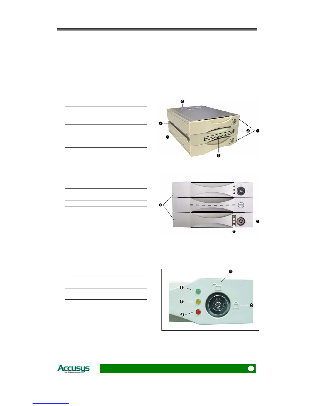
FAMILIARIZING YOURSELF WITH THE CONTROLLER ................................................... 9
Overview.............................................................................................................. 9
Front view............................................................................................................ 9
Rear view ........................................................................................................... 11
CHAPTER 2 .................................................................................................................. 12
B
B
BE
E
EF
F
FO
O
OR
R
RE
E
E
Y
Y
YO
O
OU
U
U
B
B
BE
E
EG
G
GI
I
IN
N
N
.................................................................................... 12
PRE-INSTALLATION PLANNING ................................................................................. 12
RAID 1 ............................................................................................................... 12
PRE-INSTALLATION NOTICES.................................................................................... 14
CHAPTER 3 .................................................................................................................. 15
S
S
SE
E
ET
T
TT
T
TI
I
IN
N
NG
G
G
U
U
UP
P
P
T
T
TH
H
HE
E
E
C
C
CO
O
ON
N
NT
T
TR
R
RO
O
OL
L
LL
L
LE
E
ER
R
R
....................................................... 15
INSTALLATION FLOWCHART..................................................................................... 15
MOUNTING RAID BOX............................................................................................. 16

Accusys 75170
6
Mounting RAID box in system ........................................................................... 16
LOADING DRIVES IN THE RAID BOX......................................................................... 17
Fixed connector drive carrier............................................................................ 17
REMOVING /REPLACING A DRIVE ............................................................................. 19
Swapping drives................................................................................................. 19
What if a disk fails?............................................................................................ 19
Removing a drive from a fixed connector drive carrier..................................... 19
FIRMWARE UPDATING STEPS.............................................................................. 20
CHAPTER 4 .................................................................................................................. 22
A
A
AP
P
PP
P
PL
L
LI
I
IC
C
CA
A
AT
T
TI
I
IO
O
ON
N
N
.................................................................................................... 22
Application 1: Two new disk drives (identical or non-identical)....................... 22
Application 2: Installing one drive with data and one new drive ...................... 22
APPENDIX A................................................................................................................ 23
F
F
FA
A
AQ
Q
Q
............................................................................................................................. 23
APPENDIX B................................................................................................................ 24
G
G
GL
L
LO
O
OS
S
SS
S
SA
A
AR
R
RY
Y
Y
........................................................................................................... 24
APPENDIX C................................................................................................................ 26
S
S
SP
P
PE
E
EC
C
CI
I
IF
F
FI
I
IC
C
CA
A
AT
T
TI
I
IO
O
ON
N
NS
S
S
............................................................................................ 26
APPENDIX D................................................................................................................ 27
R
R
RE
E
EG
G
GU
U
UL
L
LA
A
AT
T
TO
O
OR
R
RY
Y
Y
I
I
IN
N
NF
F
FO
O
OR
R
RM
M
MA
A
AT
T
TI
I
IO
O
ON
N
N
........................................................... 27
APPENDIX E................................................................................................................ 28
C
C
CO
O
ON
N
NT
T
TA
A
AC
C
CT
T
T
U
U
US
S
S
...................................................................................................... 28
ACCUSYS,INC.......................................................................................................... 28
ACCUSYS U.S.A., INC. ............................................................................................. 28
ACCUSYS KOREA,INC.............................................................................................. 28
ACCUSYS CHINA,INC............................................................................................... 28
ACCUSYS EU, BV.................................................................................................... 29

Chapter 1 – Introduction
7
C
Ch
ha
ap
pt
te
er
r
1
1
I
I
In
n
nt
t
tr
r
ro
o
od
d
du
u
uc
c
ct
t
ti
i
io
o
on
n
n
This chapter introduces the features and capabilities of
ACS-75170.
You will find:
A full introduction to your ACS-75170 controller
Details of key features
A checklist of package contents
A checklist of what else you need to start installation
An overview of the RAID box and its features, including
connectors, LEDs and jumpers
Overview
Congratulations on your selection of the Accusys 75170 (ACS-75170). The ACS-75170 is a
high-performance and extremely flexible solution for RAID 1 disk mirroring. With a cost
effective SATA approach, the ACS-75170 mirrors data to the other disk drive simultaneously,
and delivers optimized performance. If one drive fails, data is secured by the other drive and
alarm sounds to alert you.
Featuring intelligent online recovery, ACS-75170 let you hot swap a failed drive and it
automatically rebuilds the data to the new drive without any system down time. The 75170
RAID box features a user-friendly rack design that lets you easily install a backup drive, or
replace a drive that fails. Each hard drive carrier supports a one-inch high 3.5 inch for factor
disk drive. Additional data security is provided by a key-locking system, that prevents
unauthorized access to each disk drive.

Accusys 75170
8
Key features
The ACS-75170 supports the following features:
Support 2 SATA-I disk channels
Support one SATA-I host channel
Support RAID level 1
OS independent (No driver needed)
2MByte memory buffer
Support front panel disk operation LED indicator
Disk hot swapping supported
Automatic drive failure detection
Automatic on-line drive re-build
Audible alarm on drive failure
Battery backup for disk rebuild status
Support ATA-6 big drive function
Support GUI 7 series spec. (Rev. 1.01 or above)
Hard drive hot swapping
Hot Swapping allows for the removal and installation of disk drives without the need to power
down the system while ACS-75170 is configured as a RAID 1 array.
Automatic drive rebuilding
If a member drive in a RAID 1 array is replaced on-line, the controller will automatically start to
rebuild data to the new drive.
Making sure you have everything
What's in the box
Some vendors may ship certain components as standard, while other vendors treat the same
component as optional. In its most basic configuration, your package should include the
following:
ACS-75170 RAID Box
ACS-75170 Controller User’s Manual and GUI management software
Two disk drive carriers with key locks
Disk drive mounting screws
Two keys for drive carriers (identical)
What else you need
In order to setup a working system the following user-supplied items are required:
System with SATA Interface
Case with two half-height 5 ¼” drive bays with front bezel access
One SATA channel cable connector
One free power supply connector at least
One 3-pin RS232 cable connector (data connection for GUI interface, if required)

Chapter 1 – Introduction
9
Familiarizing yourself with the controller
Overview
The RAID box has two drive carriers, accessed from the front.
The sides of the box each feature a guide rail channel and mounting screw holes to enable
the box to be secured inside a computer case.
The connectors and jumpers are located on the rear panel.
Top /Down Drive carrier
Rebuilding activity/Error message
indicator
Disk status/ Rebuild indicators
Guide rail channel
Holes for mounting screws
Rear / Connectors & jumpers
Front view
Two Drive Carriers
Disk Activity Indicators
Drive Carrier Lock
Each drive carrier can hold a one-inch high 3.5-inch form factor hard disk drive. This makes it
easy to hot swap a drive in the event of a failure, without affecting the status of the remaining
drives.
Drive Carrier Lock – Unlocked
orientation
Drive Carrier Lock – Locked
orientation
Green Disk Activity Indicator
Amber Disk Activity Indicator
Red Disk Activity Indicator

Accusys 75170
10
Disk Activity Indicators
These indicators show the status of each individual disk drive.
Indicator Disk Activity
Green Disk drive is properly installed and locked
Amber Disk drive is being accessed
Red Disk drive is not present, is not properly
installed, is unlocked, or disk has failed
Red Flashing Disk drive is rebuilding data.
In the event that a drive fails, the Red indicator turns on and an alarm sounds. You can turn off
the alarm by unlocking the drive carrier.
The drive carrier lock acts as an On/Off switch for the drives and
provides security by preventing non-key holders from accessing the
drives.
To lock each carrier, insert the key and turn it in a clockwise
direction. To unlock a carrier, turn the key in a counterclockwise
direction.
Disk Status/ Rebuild Indicators
The upper indicator represents the top drive carrier, the lower indicator represents the bottom
drive carrier. If a drive fails, the appropriate indicator turns on and an audible alarm sounds.
You can turn off the audible alarm by unlocking the drive carrier.
The red indicator of the target disk will light up and blink while rebuilding.
Rebuilding Activity/ Error Message Indicator
Rebuilding Activity:
This row of eight indicators shows disks rebuilding activity. In normal operation, a green light
scans across the bank of indicators. If you are using the online recovery feature to rebuild a
drive, all the indicators will turn on at the same time. The left-side indicator blinks and then
turns off when 12.5% of the data has been mirrored. Then the next indicator blinks and turns
off when 25% of the data has been mirrored, and so on.
Error Message
The chart offers the all-possible error messages, and can help you to identify certain
problems.
★Drive carriers LED Error Status Display
☆Disk Fail (Replace the failed disk with another disk)
☆Target Disk Size small than Source Disk (Replace the failed target disk with a disk
that its size is greater or equal to the source disk.)

Chapter 1 – Introduction
11
☆Disk has bad sector (replace the failed disk with another disk)
☆Fan Fail (Contact with Accusys product support center)
☆No battery (Contact with Accusys product support center)
☆Power ON Channel 1 Fail (Call or email Accusys product support center)
☆Power ON Channel 2 Fail (Call or email Accusys product support center)
Rear view
Connector for SATA interface
cable
RAID level configuration jumper
pins
Power connector
3-pin RS232 connector (Terminal
port)
Cooling fan vent
The SATA cable is the route used for reading and writing to the array.
The power connector supplies power to the controller box. In order to provide stable power,
we recommend to connect both power connectors on the RAID box.
The 3-pin RS-232 cable is used for remote monitoring of ACS-75170. The RS-232 port is
configured with DTE and PC compatible pin assignments.
There is a triangular symbol “▲” on both PCB connector and RS-232 cable connector,
please make sure you connect in the right direction (both triangle symbols match each
other). Connecting in wrong direction will not damage RAID controller, however the terminal
or GUI will not work.
The cooling fan inside the RAID box provides air circulation for the disk drives.
DO NOT change the RAID level configuration jumpers. They have been set
and ready for use when the controller is delivered.

Accusys 75170
12
C
Ch
ha
ap
pt
te
er
r
2
2
B
B
Be
e
ef
f
fo
o
or
r
re
e
e
y
y
yo
o
ou
u
u
b
b
be
e
eg
g
gi
i
in
n
n
This chapter contains includes all the information about RAID
level and preparing for installation. You will find:
A full introduction to and comparison of RAID level 1
Important notices on the safe operation and installation of
ACS-75170
Pre-installation planning
RAID 1
The ACS-75170 can support the following RAID level 1. RAID 1 is commonly referred to as
Disk Mirroring, Disk Shadowing or Disk Duplexing as all data is duplicated across both disks.
RAID 1 can only be performed with two hard drives (with four drives, RAID 0+1 is configured
automatically). As data is identical on both disks, storage capacity is that of the smaller disk.
RAID 1 has poor performance for write operations but very high performance for read
intensive operations. Further information on RAID concepts can be found in Appendix B,
Glossary.
RAID 1: Mirroring
Characteristics: Recommended use:
Better Read transaction rate then single disks,
same Write transaction rate as single disks.
100% redundancy of data means no rebuild of
data is necessary in case of disk failure, just a
copy to the replacement disk.
All the disks have the same data.
Raid level 1 requires two drives.
Storage capacity = Capacity of smaller disk
Accounting
Payroll
Financial
Any application
requiring high
availability

Chapter 2 – Before you begin
13
Arrangement of data blocks saved on a Level 1 array

Accusys 75170
14
Pre-installation notices
Before starting any kind of hardware installation, please ensure that all power
switches have been turned off and all power cords disconnected to prevent
personal injury and damage to the hardware.
To avoid overheating, ACS-75170 should be installed in a well-ventilated area
and in such a way that sufficient airflow is maintained across the controller
chips.
Static electricity can damage electronic components. To guard against such
damage:
Work in a static-free environment
Wear a grounded anti-static wrist strap
Store uninstalled components in anti-static bags
Handle PCBs by their edges and avoid touching chips and connectors.
Environmental requirements: Temperature: 0-50
℃
Operating Humidity: 5-95%, non-condensing
Storage Humidty: 5-75%

Chapter 3 –Setting up the controller
15
C
Ch
ha
ap
pt
te
er
r
3
3
S
S
Se
e
et
t
tt
t
ti
i
in
n
ng
g
g
u
u
up
p
p
t
t
th
h
he
e
e
c
c
co
o
on
n
nt
t
tr
r
ro
o
ol
l
ll
l
le
e
er
r
r
This chapter explains how to:
Check RAID level on RAID box
Install the RAID controller in a system or externally
Load hard drives into ACS-75170
Swap drives
Installation flowchart
Installation of ACS-75170 is simple. This chapter will lead you though the following steps:
When the controller is fully configured, connect a power and
SATA cable and install it either in a system or externally.
When the controller is installed, load a hard drive into each of
the drive carriers
Install
controller
Load hard
drives

Accusys 75170
16
Mounting RAID box
The ACS-75170 RAID box can be installed inside a computer case or set up externally. This
section describes both procedures.
Turn off and disconnect all electrical power from the system before beginning
installation.
Mounting RAID box in system
The ACS-75170 RAID box fits into the space of the half-height 5¼-inch drive bay.
1. Remove the cover and front bezel from
the system case.
2. Feed a power cable through the
opening.
3. Feed an SATA cable through the
opening.
4. Connect the two cables to the connectors
on the rear of the RAID box.
5. If planning to use the ACSView GUI to
monitor the status of your RAID, you
should also connect a 3-pin RS-232 cable
to the terminal on the RAID box.
6. Insert the RAID box into the bay, and
secure it in place with the screws provided.
(If your case uses guide rails to install
5¼-inch devices, you can use them on the
RAID box.)
In order to provide stable power, we recommend to connect both power connectors on the RAID box.

Chapter 3 –Setting up the controller
17
Loading drives in the R
R
RA
A
AI
I
ID
D
D
b
b
bo
o
ox
x
x
There one type of drive carrier available for ACS-75170 controller:
1. Fixed SATA connector
Drive Carrier
Fixed SATA Connector
Fixed connector drive carrier
The ACS-75170 should be fitted with two hard disk drives. Load each drive into a drive carrier
as follows:
Unlock the drive carrier and slide it out of the
controller box.
2. Place the disk drive in the drive carrier, so
that the SATA connector is lined up with
the connector inside the carrier.
3. Carefully push the disk drive so that the
drive’s SATA connector is seated securely
into the SATA connector in the disk carrier.
4. Secure the disk drive by screwing it to the
drive carrier case.
5. Slide the loaded disk drive carrier into the
ACS-75170 RAID Box and lock it.

Accusys 75170
18
The disk carrier connector at the back of each RAID box disk carrier slot can
be damaged if the disk carrier is not properly aligned when inserted. Insert the
disk carrier gently to avoid damage.

Chapter 3 –Setting up the controller
19
Removing / replacing a drive
Swapping drives
The hot swap function is available on the RAID 1 array and can be operated during run time.
RAID rebuilding will be processed automatically in the background and the ACS-75170 RAID
subsystem will record its progress. If the host system is shut down or powered off abnormally,
the ACS-75170 RAID subsystem will continue the disk rebuilding process after power is turned
on again.
A hard disk should not be replaced when the system is turned off. Doing so
may leads to loss of data.
What if a disk fails?
If a disk drive fails, or a key switch is turned off, the red disk activity indicator of its disk carrier
will light and the alarm will sound (sound when only disk fails). When this happens, you can
replace the failed disk with a new one, then turn the key switch on.
Removing a drive from a fixed connector drive carrier
1. Unlock the appropriate disk carrier. The
red disk activity indicator will light.
2. Slide the drive carrier out of its slot.
3. Slide the disk drive to the front of the
carrier so that the SATA connector is freed
from the drive carrier.
4. Lift out the disk drive.

Accusys 75170
20
F
Fi
ir
rm
mw
wa
ar
re
e
u
up
pd
da
at
ti
in
ng
g
s
st
te
ep
ps
s
1. Ensure the ACS-75170 is turned off.
2. Connect the RS-232 cable to the RS-232 3pin port (Please refer the page 11 “Rear View”),
and connect the other end to one of the host computer’s COM port.
3. Launch HyperTerminal from the host computer: Start > Programs > Accessories >
Communications > HyperTerminal.
4. Select COM1 or COM2 from the Connect using: dropdown menu, depending on which port
is connecter to ACS-75170.
5. The COM properties dialog box will appear. Set the following values:
Bit per second: 19200
Data bits: 8
Parity: None
Stop bits: 1
Flow Control: Xon/Xoff
Table of contents
Other Accusys Computer Hardware manuals