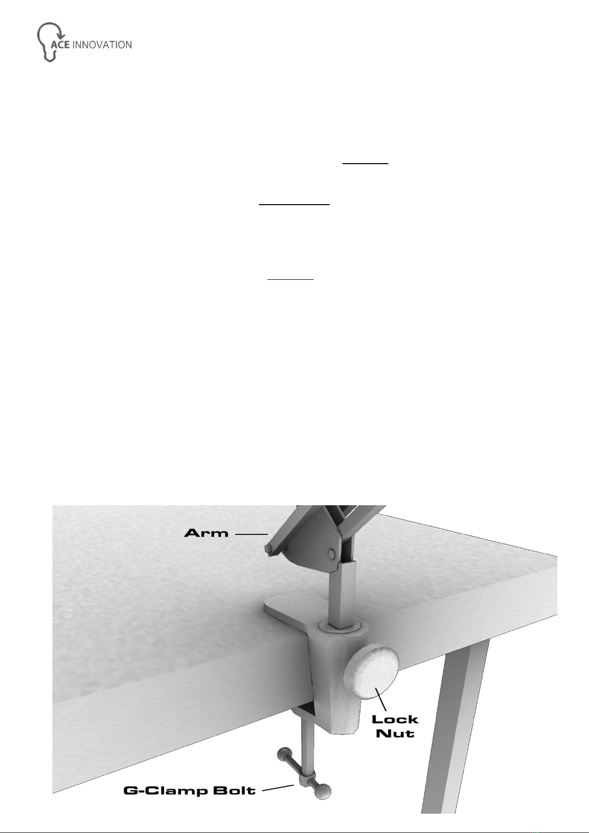
Ace Innovation SuperVisor Owner's manual

www.aceinnovation.co.uk
08455 199181
SuperVisor®
Assembly & User Instructions
Thank you for purchasing an Ace Innovation SuperVisor®
PLEASE READ THESE INSTRUCTIONS CAREFULLY BEFORE ATTEMPTING ASSEMBLY
Assembly
Assembly Step 1 –Use the diagram below to help
1. Attach the supplied G-Clamp to a suitable stable surface and secure it tightly using
the integrated bolt. *WARNING* DO NOT attach the G-Clamp if you feel that it may
cause any damage to the surface you are mounting it on. If the G-Clamp is not
suitable you will need to contact your supplier and order the SuperVisor® weighted
base.
2. *WARNING* Care should be taken when unpacking the SuperVisor® Arm as it is
spring operated and unbalanced until the Visor element is installed [See Fig 2].
3. Once the G-Clamp or weighted base is secure, loosen off the lock nut [See Fig 1]
and lower the end of the SuperVisor® Arm into the top hole of the clamp or base.
Once the Arm is fully inserted, tighten the lock nut to secure it.
Fig 1

Assembly Step 2 –Use the diagram below to help
1. Unscrew and remove ONLY the Upper Flange Nut from the SuperVisor® Arm.
*WARNING* DO NOT attempt to unscrew the Lower Flange Nut as it has already
been fixed in the correct position.
2. Ensure that the Ball Socket Assembly is in an upright position (see Fig 2) and fully
tighten the Upper Arm Lock Nut (See Fig 3).
3. Remove the SuperVisor® Lightweight Visor from its protective sleeve. As shown in
[Fig 2] the diagram, please ensure that the Visor is mounted on the Arm with the
socket for the Upper Flange Nut and the SuperVisor® logo facing upwards.
4. Lower the Visor onto the rubber grip surface of the Lower Flange Nut by pushing
the Screw Thread through the hole in the Visor. The Screw Thread is a snug fit, so
on a new Visor you may also have to gently rotate or rock the Visor from side to
side in order to encourage the thread through the hole.
5. Please ensure that the Lower Flange Nut always remains at the bottom of the
Screw Thread. If it has started to move up the Screw Thread, simply rotate it back
to the bottom.
6. Once the Visor is in position on the rubber grip, screw the Upper Flange Nut back
onto the Screw Thread on top of the Visor. As the Upper Flange Nut is tightened it
will begin to lower into the recess on the top of the Visor. Please be careful not to
over tighten the nut.
Fig 2

Adjustments
Adjustments –Use the diagrams below to help
The SuperVisor® is extremely versatile and can be adjusted in many different ways in
order to meet your requirements. When adjusting the Angle and Tilt level of your Visor;
to prevent damage please ONLY handle the Visor at the end which is connected to the
Arm.
Height –The SuperVisor® is so well balanced the height of the Arm can be adjusted
using a single finger to simply raise or lower it. The closer you have the
Visor, the larger the area blocked from your visual field. This can be
extremely useful if you are affected by more than one ceiling light.
Angle –The angle of the Visor can be adjusted by loosening the Ball Joint Lock Nut
[see Fig 3] located directly below the Visor. Once the desired angle has been
achieved, simple re-tighten the Ball Joint Lock Nut. Adjusting the angle of the
Visor is perfect for blocking light which is not located directly above you. The
Ball Joint also has a special slot which allows the Visor to be angled vertically.
This can be ideal for blocking light from side windows.
Tilt –The Tilt of the Visor can be adjusted by loosening the Ball Joint Lock Nut [see
Fig 4] located on the Ball Joint directly below the Visor. Once the desired Tilt
level has been achieved, simple re-tighten the Ball Joint Lock Nut. Adjusting
the Tilt and Angle of the Visor is extremely useful for blocking light which is
emanating from a more challenging location and causing problems.
Fig 3

Fig 4
Warranty
Ace Innovation warrants the SuperVisor®, when purchased new, to be free from defects
in material and workmanship and will repair or replace, at Ace Innovation’s discretion, any
equipment which exhibits such defects; provided that the equipment has been installed
and operated under normal conditions and has not been tampered with by any persons
not authorised by Ace Innovation or its agents.
On no occasion shall Ace Innovation or its agents be liable for indirect, incidental or
consequential damages; the original user’s remedies being limited to repair or
replacement.
Ace Innovation makes no other or further warranty, express or implied, including
warranty of fitness for a specific purpose or warranty of merchantability.
This warranty is valid for a period of 12 months effective from the date of delivery.
Disclaimer
The Visor element of the SuperVisor® is made from a lightweight material which, during
manufacture and general use, may acquire superficial marks and indentations. This does
not affect the function, or impact on the operation of your SuperVisor® and is therefore
not covered by the warranty.
Note that this product is not designed for use by individual minors or unsupervised
children due to the mechanical operation of its components.
Due to the operating nature of this product care must be taken to ensure articles of
clothing or limbs do not foul the operating mechanism.
www.aceinnovation.co.uk
08455 199181
Table of contents