Full manuals available online or use QR code
14300 De La Tour Drive
South Beloit, IL 61080
Phone: (815) 624-6915
Fax: (815) 624-6965
www.americancontrolelectronics.com
1Q PWM Chassis Adjustable Speed Drive
with Quick Disconnect Terminal
for PMDC Brushed Motors
PWP100
An ISO 9001:2008 Certified Company
PWP100-QDT
.............................................................115 VAC ± 10%, 50/60 Hz, single phase
..........................................................................................................................1.05
..............................................................................................1 second
............................................................................................2 seconds
.................................0 - 5 VDC
....................................................................................> 100K ohms
..................................................................................................1% base speed
........................................................................................................................80:1
............................................................................................0.5G maximum
...............................................................................................0.1G maximum
...................................................................................10°C - 40°C
..............................................................................................................................0.6 lbs
AC Line Voltage
Form Factor
Acceleraon Time Range
Deceleraon Time Range
Analog Input Voltage Range (Signal must be isolated; S1 to S2)
Input Impedance (S1 to S2)
Load Regulaon
Speed Range
Vibraon (0 - 50 Hz)
(>50 Hz)
Ambient Temperature Range
Weight
1/20 - 1/6
Horsepower
Range
2.0
Connuous
Armature
Current (Amps)
0 - 130
Armature
Voltage Range
(VDC)
115
Line
Voltage
(VAC)
PWP100-2-QDT
Model
Specifications Safety Warnings
• DO NOT INSTALL, REMOVE, OR REWIRE THIS EQUIPMENT WITH POWER APPLIED. Have a
• qualified electrical technician install, adjust and service this equipment. Follow the Naonal
• Electrical Code and all other applicable electrical and safety codes, including the provisions of the
• Occupaonal Safety and Health Act (OSHA), when installing equipment.
• Circuit potenals are at 115 VAC above earth ground. Avoid direct contact with the printed
• circuit board or with circuit elements to prevent the risk of serious injury or fatality. Use a non-
• metallic screwdriver for adjusng the calibraon trim pots. Use approved personal protecon
• equipment and insulated tools if working on this drive with power applied.
• Reduce the chance of an electrical fire, shock, or explosion by using proper grounding techniques,
• over-current protecon, thermal protecon, and enclosure. Follow sound maintenance procedures.
• ACE strongly recommends the installaon of a master power switch in the line voltage input. The
• switch contacts should be rated for 250 VAC and 200% of motor nameplate current.
• Do not disconnect any of the motor leads from the drive unless power is removed or the drive is
• disabled. Opening any one lead while the drive is running may destroy the drive.
• Under no circumstances should power and logic level wires be bundled together.
• Be sure potenometer tabs do no make contact with the potenometer’s body. Grounding the
• input will cause damage to the drive.
ALL DIMENSIONS IN INCHES [MILLIMETERS]
Dimensions
3.58 [91]
0.74 [19]
1.75 [44]
0.19 [5]
0.65 [16]
3.80 [97]
4.30 [109]
2.15 [55]
0.97 [25]
1.28 [33]
0.19 [5]
MAX SPD
P501
TORQUE
P502
MIN SPD
P503
IR COMP
P504
Installation
Mounng
• Drive components are sensive to electrostac discharge. Avoid direct contact with the circuit
• board. Hold the drive by the chassis or heat sink only.
• Protect the drive from dirt, moisture, and accidental contact.
• Provide sufficient room for access to the terminal block and calibraon trim pots.
• Mount the drive away from heat sources. Operate the drive within the specified ambient operang
• temperature range.
• Prevent loose connecons by avoiding excessive vibraon of the drive.
• Mount the drive with its board in either a horizontal or vercal plane. Six 0.19” (5 mm) wide slots
• in the chassis accept #8 pan head screws. Fasten either the large base or the narrow flange of the
• chassis to the subplate.
• The chassis should be earth grounded. Use a star washer beneath the head of at least one of the
• mounng screws to penetrate the anodized chassis surface and to reach bare metal.
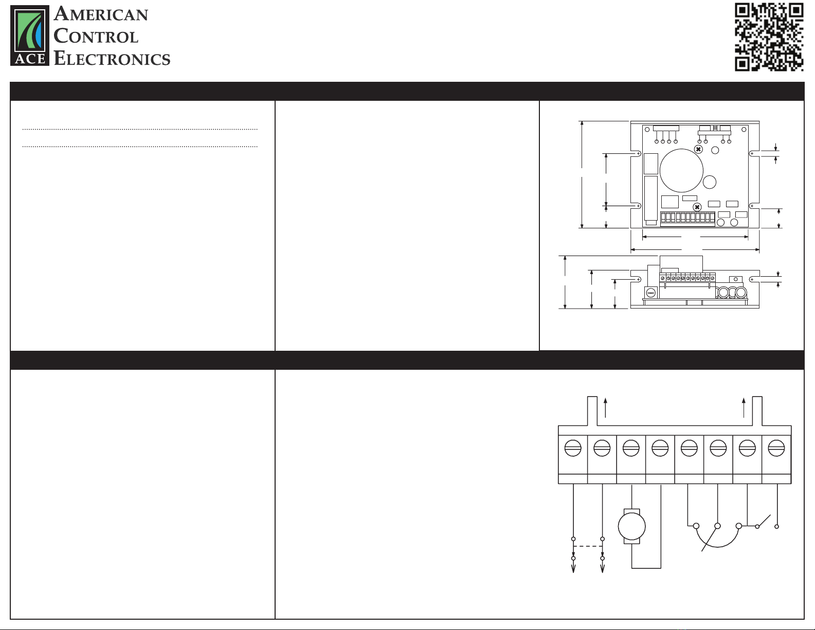
Wiring
Use 18 - 24 AWG wire for logic wiring. Use 14 - 16 AWG wire for AC line and motor wiring.
Shielding Guidelines
As a general rule, ACE recommends shielding of all conductors. If it is not praccal to shield power
conductors, ACE recommends shielding all logic-level leads. If shielding of logic-level leads is not
praccal, the user should twist all logic leads with themselves to minimize induced noise. It may be
necessary to earth ground the shielded cable. If noise is produced by devices other than the drive,
ground the shield at the drive end. If noise is generated by the drive, ground the shield at the end
away from the drive. Do not ground both ends of the shield.
Fusing
PWP100-QDT series drives provide an on board fuse for the AC line (L1). Fuse is a fasng acng fuse
rated for 5A at 250 VAC.
Line Input
Connect the AC line power leads to terminals L1 and L2. ACE recommends the use of a double-pole,
single-throw master power switch. The switch should be rated at a minimum of 250 VAC and 200% of motor
current.
Motor
Connect the DC armature leads to terminals A1 and A2. If the motor does not spin in the desired direcon,
power down the drive and reverse these connecons.
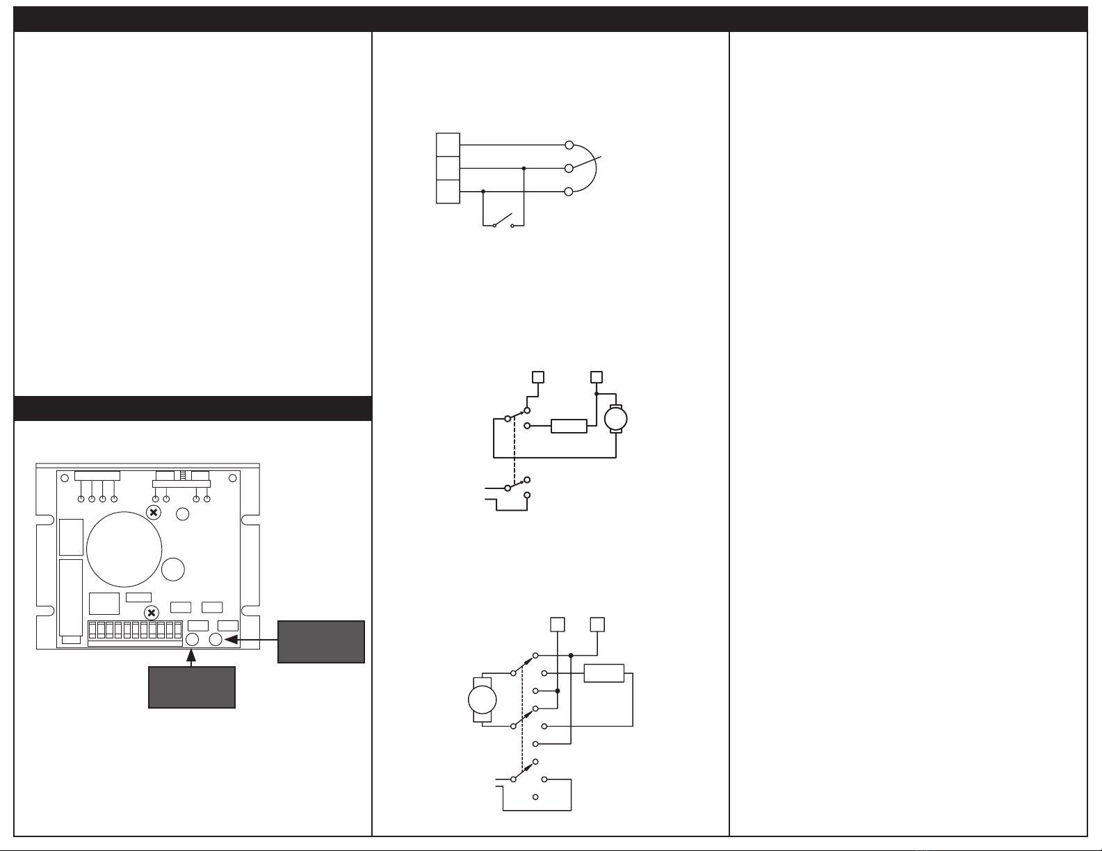
Speed Potenometer
Use a 10K ohm, 1/4 W potenometer for speed control. Connect the counter-clockwise end of the
potenometer to S1, the wiper to S2, and the clockwise end to S3. If the potenometer works inversely of
desired funconality, (i.e. to increase motor speed, you must turn the potenometer counterclockwise),
power off the drive and swap the S1 and S3 connecons.
Run/Stop Switch
Wire a normally open switch to terminals H1 and H2. Closing the switch will stop the motor. If no Run/Stop
is desired, do not connect anything between terminals H1 and H2. Do not use Run/Stop switch for
emergency stopping.
Connections
STOP
SWITCH
A1 A2L1 L2 H2
S1
S2S3
10K OHM
SPEED ADJUST
POTENTIOMETER
CW
MOTOR
ARMATURE
CONNECT TO HEADER BLOCK
H1
RUN
STOP
POWER
LOGIC