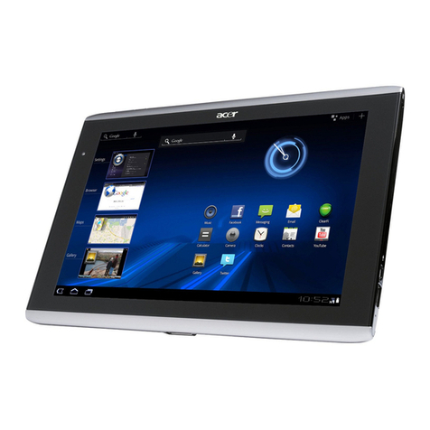
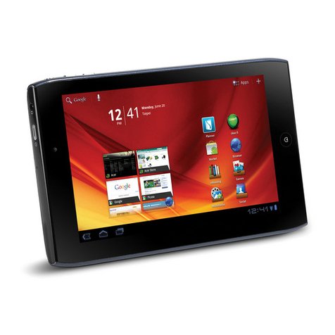
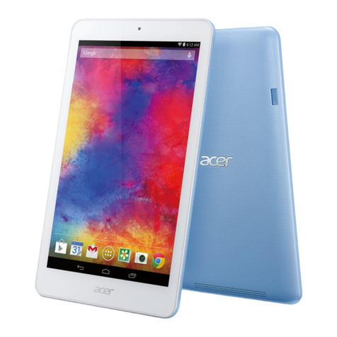
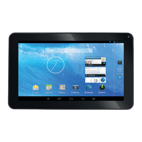
Acer TD070VA1 User manual

TD070VA1
SERVICE GUIDE

Table of Contents
Chapter 1. Hardware Specifications and Configurations
Features . . . . . . . . . . . . . . . . . . . . . . . . . . . . . . . . . . . . . . . . . . . . . . . . . . . . . . . . . . . .
Tablet tour. . . . . . . . . . . . . . . . . . . . . . . . . . . . . . . . . . . . . . . . . . . . . . . . . . . . . . . . . . .
Front View . . . . . . . . . . . . . . . . . . . . . . . . . . . . . . . . . . . . . . . . . . . . . . . . . . . .
Rear View . . . . . . . . . . . . . . . . . . . . . . . . . . . . . . . . . . . . . . . . . . . . . . . . . . . .
Top View . . . . . . . . . . . . . . . . . . . . . . . . . . . . . . . . . . . . . . . . . . . . . . . . . . . . .
Bottom View. . . . . . . . . . . . . . . . . . . . . . . . . . . . . . . . . . . . . . . . . . . . . . . . . . .
Right View . . . . . . . . . . . . . . . . . . . . . . . . . . . . . . . . . . . . . . . . . . . . . . . . . . . .
System Block Diagram . . . . . . . . . . . . . . . . . . . . . . . . . . . . . . . . . . . . . . . . . . . . . . . . .
Specifications Table . . . . . . . . . . . . . . . . . . . . . . . . . . . . . . . . . . . . . . . . . . . . . . . . . . .
1-2
1-5
1-5
1-6
1-7
1-7
1-8
1-9
1-10
Chapter 2. Diagnostic Utilities
Introduction . . . . . . . . . . . . . . . . . . . . . . . . . . . . . . . . . . . . . . . . . . . . . . . . . . . . . . . . . . 2-2
Diagnostic Tool SOP . . . . . . . . . . . . . . . . . . . . . . . . . . . . . . . . . . . . . . . . . . . . . . . . . . 2-2
Main Menu . . . . . . . . . . . . . . . . . . . . . . . . . . . . . . . . . . . . . . . . . . . . . . . . . . . 2-3
Chapter 3. Jumper and Connector Locations
Mainboard Top View . . . . . . . . . . . . . . . . . . . . . . . . . . . . . . . . . . . . . . . . . . . . . . . . . . . 3-2
Mainboard Bottom View . . . . . . . . . . . . . . . . . . . . . . . . . . . . . . . . . . . . . . . . . . . . . . . . 3-3
Chapter 4. Troubleshooting
General Information . . . . . . . . . . . . . . . . . . . . . . . . . . . . . . . . . . . . . . . . . . . . . . . . . . .
Power On Issues . . . . . . . . . . . . . . . . . . . . . . . . . . . . . . . . . . . . . . . . . . . . . . .
No Display Issues . . . . . . . . . . . . . . . . . . . . . . . . . . . . . . . . . . . . . . . . . . . . . .
LCD Picture Failure . . . . . . . . . . . . . . . . . . . . . . . . . . . . . . . . . . . . . . . . . . . . .
Touch Screen Failure. . . . . . . . . . . . . . . . . . . . . . . . . . . . . . . . . . . . . . . . . . . .
Internal Speaker Failure. . . . . . . . . . . . . . . . . . . . . . . . . . . . . . . . . . . . . . . . . .
Internal Microphone Failure . . . . . . . . . . . . . . . . . . . . . . . . . . . . . . . . . . . . . . .
Extend Earphone Failure . . . . . . . . . . . . . . . . . . . . . . . . . . . . . . . . . . . . . . . . .
USB Test Failure . . . . . . . . . . . . . . . . . . . . . . . . . . . . . . . . . . . . . . . . . . . . . . .
Front Camera Failure . . . . . . . . . . . . . . . . . . . . . . . . . . . . . . . . . . . . . . . . . . . .
WiFi Function Test Failure . . . . . . . . . . . . . . . . . . . . . . . . . . . . . . . . . . . . . . . .
GPS Function Test Failure. . . . . . . . . . . . . . . . . . . . . . . . . . . . . . . . . . . . . . . .
Other Functions Failure . . . . . . . . . . . . . . . . . . . . . . . . . . . . . . . . . . . . . . . . . .
4-2
4-3
4-4
4-5
4-6
4-7
4-8
4-9
4-10
4-11
4-12
4-13
4-14
Chapter 5. Service and Maintenance
Introduction . . . . . . . . . . . . . . . . . . . . . . . . . . . . . . . . . . . . . . . . . . . . . . . . . . . . . . . . . .
Recommended Equipment . . . . . . . . . . . . . . . . . . . . . . . . . . . . . . . . . . . . . . . . . . . . . .
Maintenance Flowchart. . . . . . . . . . . . . . . . . . . . . . . . . . . . . . . . . . . . . . . . . . . . . . . . .
Getting Started . . . . . . . . . . . . . . . . . . . . . . . . . . . . . . . . . . . . . . . . . . . . . . . . . . . . . . .
Micro SD Card Removal . . . . . . . . . . . . . . . . . . . . . . . . . . . . . . . . . . . . . .
Micro SD Card Installation . . . . . . . . . . . . . . . . . . . . . . . . . . . . . . . . . . . . ..
Rear Cover Removal. . . . . . . . . . . . . . . . . . . . . . . . . . . . . . . . . . . . . . . . . .
Rear Cover Installation . . . . . . . . . . . . . . . . . . . . . . . . . . . . . . . . . . . . . . . .
Mainboard Removal . . . . . . . . . . . . . . . . . . . . . . . . . . . . . . . . . . . . . . . . . .
Mainboard Installation . . . . . . . . . . . . . . . . . . . . . . . . . . . . . . . . . . . . . . . .
TP Removal . . . . . . . . . . . . . . . . . . . . . . . . . . . . . . . . . . . . . . . . . . . . . . . .
TP Installation . . . . . . . . . . . . . . . . . . . . . . . . . . . . . . . . . . . . . . . . . . . . . . .
LCD Removal . . . . . . . . . . . . . . . . . . . . . . . . . . . . . . . . . . . . . . . . . . . . . . .
LCD Installation . . . . . . . . . . . . . . . . . . . . . . . . . . . . . . . . . . . . . . . . . . . . .
WIFI Antenna Removal . . . . . . . . . . . . . . . . . . . . . . . . . . . . . . . . . . . . . . . .
5-2
5-2
5-3
5-4
5-5
5-6
5-7
5-11
5-8
5-18
5-17
5-9
5-17
5-10
5-9
i

WIFI Antenna Installation . . . . . . . . . . . . . . . . . . . . . . . . . . . . . . . . . . . . . . .
Camera Module Removal . . . . . . . . . . . . . . . . . . . . . . . . . . . . . . . . . . . . . . . .
Camera Module Installation . . . . . . . . . . . . . . . . . . . . . . . . . . . . . . . . . . . . . .
Battery Removal . . . . . . . . . . . . . . . . . . . . . . . . . . . . . . . . . . . . . . . . . . . . . . .
Battery Installation . . . . . . . . . . . . . . . . . . . . . . . . . . . . . . . . . . . . . . . . . . . . .
5-19
5-9
5-21
5-9
5-22
Chapter 6. FRU (Field Replaceable Unit) List
Exploded Diagram . . . . . . . . . . . . . . . . . . . . . . . . . . . . . . . . . . . . . . . . . . . . . . . . . . 6-3
FRU List . . . . . . . . . . . . . . . . . . . . . . . . . . . . . . . . . . . . . . . . . . . . . . . . . . . . . . . . . . 6-5
Screw List . . . . . . . . . . . . . . . . . . . . . . . . . . . . . . . . . . . . . . . . . . . . . . . . . . . . . . . . . 6-7
Chapter 7. Test Compatible Components
Android OS Environment Test . . . . . . . . . . . . . . . . . . . . . . . . . . . . . . . . . . . . . . . . . . 7-2
TD070VA1 . . . . . . . . . . . . . . . . . . . . . . . . . . . . . . . . . . . . . . . . . . . . . . . . . . 7-2
Chapter 8. Online Support Information
Introduction . . . . . . . . . . . . . . . . . . . . . . . . . . . . . . . . . . . . . . . . . . . . . . . . . . . . . . . . . . 8-2
ii

Revision History
Please refer to the table below for the updates made on this service guide.
Date
Chapter
Updates
Copyright
Copyright © 2013 by Acer Incorporated. All rights reserved. No part of this publication may be
reproduced, transmitted, transcribed, stored in a retrieval system, or translated into any language
or computer language, in any form or by any means, electronic, mechanical, magnetic, optical,
chemical, manual or otherwise, without the prior written permission of Acer Incorporated.
Disclaimer
The information in this guide is subject to change without notice.
Acer Incorporated makes no representations or warranties, either expressed or implied, with
respect to the contents hereof and specifically disclaims any warranties of merchantability or fitness
for any particular purpose. Any Acer Incorporated software described in this manual is sold or
licensed "as is". Should the programs prove defective following their purchase, the buyer (and not
Acer Incorporated, its distributor, or its dealer) assumes the entire cost of all necessary servicing,
repair, and any incidental or consequential damages resulting from any defect in the software.
Acer is a registered trademark of Acer Corporation.
VIA is a registered trademark of VIA Corporation.
Other brand and product names are trademarks and/or registered trademarks of their respective
holders.
iii

Conventions
The following conventions are used in this manual:
WARNING:
Indicates a potential for personal injury.
CAUTION:
Indicates a potential loss of data or damage to equipment.
IMPORTANT:
Indicates information that is important to know for the proper completion of a
procedure, choice of an option, or completing a task.
NOTE:
Gives bits and pieces of additional information related to the current topic.
The following typographical conventions are used in this document:
•
Book titles, directory names, file names, path names, and program/process names are shown
in italics.
Example:
the DRS5 User's Guide
/usr/local/bin/fd
the /TPH15spool_M program
•
Computer output (text that represents information displayed on a computer screen, such as
menus, prompts, responses to input, and error messages) are shown in constant width.
Example:
[01] The server has been stopped
•
User input (text that represents information entered by a computer user, such as command
names, option letters, and words) are shown in constant width bold. Variables contained within
user input are shown in angle brackets (< >).
Example:
At the prompt, type run <file name> -m
•
Keyboard keys are shown in bold italics.
Example:
After entering data, press Enter.
•
Screen output (text that represents information displayed on the system, such as menus,
prompts, responses to input, and error messages) are shown in bold.
Example:
On the main menu, select OK.
iv

General Information
This Service Guide provides you with all technical information relating to the basic configuration for
Acer's global product offering. To better fit local market requirements and enhance product
competitiveness, your regional office may have decided to extend the functionality of a machine
(e.g. add-on card, modem, or extra memory capabilities). These localized features are not covered
in this generic service guide. In such cases, contact your regional offices or the responsible
personnel/channel to provide you with further technical details.
When ordering FRU parts:
Check the most up-to-date information available on your regional web or channel. If, for whatever
reason, a part number change is made, it may not be noted in this printed service guide.
For Acer-authorized service providers:
Your Acer office may have a different part number code than those given in the FRU list of this
printed service guide. The list provided by your regional Acer office must be used to order FRU
parts for repair and service of customer machines.
v

CHAPTER 1
Hardware Specifications and Configurations
Hardware Specifications and Configurations . . . . . . . . . . . . . . . . .1-2
Features . . . . . . . . . . . . . . . . . . . . . . . . . . . . . . . . . . . . . . . . . . . . . . . . . . . . . . . 1 -2
Tablet tour . . . . . . . . . . . . . . . . . . . . . . . . . . . . . . . . . . . . . . . . . . . . . . . . . . . . . 1-5
Front View . . . . . . . . . . . . . . . . . . . . . . . . . . . . . . . . . . . . . . . . . . . . . . . . . . 1-5
Rear View . . . . . . . . . . . . . . . . . . . . . . . . . . . . . . . . . . . . . . . . . . . . . . . . . . 1-6
Bottom View . . . . . . . . . . . . . . . . . . . . . . . . . . . . . . . . . . . . . . . . . . . . . . . . 1-7
Right View . . . . . . . . . . . . . . . . . . . . . . . . . . . . . . . . . . . . . . . . . . . . . . . . . . 1-8
System Block Diagram . . . . . . . . . . . . . . . . . . . . . . . . . . . . . . . . . . . . . . . . . . . 1-9
Specifications Table . . . . . . . . . . . . . . . . . . . . . . . . . . . . . . . . . . . . . . . . . . . . 1-10

Hardware Specifications and Configurations
Features
The following is a summary of the computer’s many features:
Form Factor
•
7” Tablet
Operating System
•
Android 4.2.1
Platform
•
Cortex-A9 WM8880 1.5GHZ Dual Core Processor
System Memory
•
•
RAM: DDR3 1GB
eMMC: Nand flash 8GB/16GB
Display
LCM
•
7’’ WSVGA Color TFT LCD,1024X600 Image resolution
Low voltage
70-degree view angle
Audio Subsystem
•
•
•
Microphone
Speaker
3.5mm Audio Jack
Camera
Front Camera
0.3M Camera
Image capture at 30fps @ VGA 640 x 480
Video capture at 30fps @ VGA 640 x 480
Rear camera
1.9M Camera
Image capture at 30fps @ VGA 1280 x 720
Video capture at 30fps @ VGA1280 x 720
1-2
Hardware Specifications and Configurations

Connectivity
Wi-Fi
•
Bluetooth
•
USB
•
•
Micro USB 2.0 port
Support USB 2.0 Client
N/A
IEEE 802.11 b/g/n
Expansion Slot
MicroSD memory card up to 32G
•
Special Keys and Controls
•
•
•
Capacitive Multi-Touch Screen
Touch controller - 5 point support/
Function buttons
Side (mechanical key):
•
•
Volume Up, Volume Down
Power
G+G
Sensors
•
G-Sensor
I/O Ports
MicroSD memory Card slot
Micro USB 2.0
Micro HDMI
Headphone/Microphone-in
Dimensions and Weight
Dimension
•
Weight
•
191 (H) x 112 (W) x 9.9 (D) mm (with bezel)
289g
Hardware Specifications and Configurations
1-3

Power Adapter and Battery
Battery
•
•
Li-Polymer battery
Capacity: 3000mAh
Power Adapter
•
•
Voltage range/frequency: 100~ 240V AC, 50/60Hz
DC output: 5V,1.5A
Others
•
Reset hole
Green Requirement
•
•
•
Rohs compliance
WEEE compliance
SMT Green process
1-4
Hardware Specifications and Configurations

Tablet tour
Front View
Figure 1-1. Front View
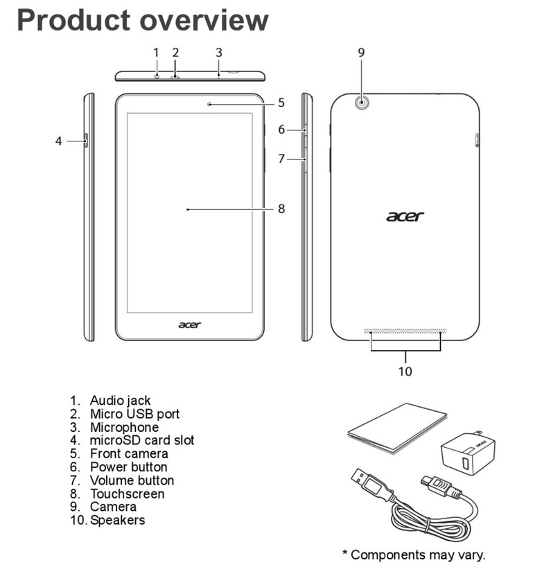
2 Front View
1 Touch Screen
Table 1-1. Front View
#
1
2
Item
Touch Screen
Front Camera
Description
7-inch, 1024 x 600 capacitive touch screen.
A 0.3-megapixel camera for video chatting and self-portrait
images.
Hardware Specifications and Configurations
1-5

Rear View
2 Rear View
1 Speakers
Figure 1-2. Rear View
Table 1-2. Rear View
#
1
Item
Speakers
Rear View
Description
Emits stereo audio.
2
1.9M Pixel Rear camera
1-6
Hardware Specifications and Configurations

Bottom View
Figure 1-4. Bottom View
#
1
2
3
4
5
6
Item
3.5mm headphone port
Microphone
Micro SD port
Mini USB port
Reset Hole
Description
General 3.5mm headphone
Receives audio input
EXT sd card
Even the computers to do data exchange
Insert a pointed object, such as a paper clip, into the reset
hole to reset the tablet to its factory defaults.
HDMI port
HDMI output
Hardware Specifications and Configurations
1-7

Right View
Figure 1-5. Right View
Table 1-5. Right View
#
1
Item
Up volume
Description
Increases the tablet volume
2
Down Volume
decreases the tablet volume.
• Press and hold to turn the tablet on or off.
• Press briefly to turn the screen on/off or enter sleep
mode.
3
Power Button
1-8
Hardware Specifications and Configurations

System Block Diagram
Figure 1-6. System Block Diagram
Hardware Specifications and Configurations
1-9

Specifications Table
Computer specifications
Item
Dimensions
Length
Width
Height (front to rear)
Weight
Input power
Operating voltage
Operating current
Temperature
Operating
Non-operating
Relative humidity
Operating
Non-operating
Maximum altitude (unpressurized)
Operating
Non-operating
Shock
Operating
Non-operating
Random vibration
Operating
Non-operating
NOTE:
Applicable product safety standards specify thermal limits for plastic surfaces. The computer
operates well within this range of temperatures.
1.644 grms
Amplitude: 105 g
Amplitude: 220 g
0 ~ 63 cm
0 ~ 2.48 in.
0% ~ 80%
0% ~ 80%
-25º~ 60ºC
-30º~ 70ºC
-13º~ 140ºF
-22º~ 158ºF
AC Input: 100~ 240V AC, 50/60Hz / DC Output: 5 V
AC Input: 0.3A / DC Output: 2.0A
191 mm
112 mm
9.9 mm
289 g
7.52 in
4.41 in
0.39 in
0.64 lb
Metric
Imperial
1-10
Hardware Specifications and Configurations

System Board Major Chips
Item
Specification
CPU
Cortex-A9 WM8880 1.5GHZ Dual Core Processor
Graphics Processor
LVDS transmitter
PMU
DDR3L
ULPI Phy for USB
Bluetooth
Wireless
GPS
GPS Low-Noise Amplifier
TOUCH controller
eMMC
Mali-400 DP
N/A
N/A
DDR3 1G
N/A
N/A
WI-FI802.11B/G/N
N/A
N/A
ZET6221/GSL1680
8G / 16G
CAMERA
1.9MP rear camera,0.3MP front camera
Thermal Sensor
Audio codec
Audio Amplifier
Echo Cancellation
Battery Charger
Embedded Controller IC
Compass
Gyro
G-Sensor
ALS/Proximity
N/A
Embedded in CPU
Embedded in PMU
N/A
VT1603A
N/A
N/A
N/A
NC3230
N/A
Hardware Specifications and Configurations
1-11

Processor
Item
Specification
Cortex-A9 WM8880 1.5GHZ Dual Core Processor+ Mali-400 DP
CPU
CPU package
N/A.
Processor Specifications
Item
CPU
Speed
Cores
Bus Speed
(FSB/DMI/QBI) Mfg Tech
Cache
Size
Package
Core
Voltage
WM8880
1.5
GHz
Dual
Core
N/A
N/A
N/A
N/A
0.9V-1.2V
No CPU Fan for this product
No BIOS Setup Menu for this product
No Keyboard for this product
System Memory-DDR3L
Item
Memory controller
Memory size
Embedded in CPU
1 GB DDR3
Specification
Hardware Specifications and Configurations
1-12

LED 7.0”
Item
Vendor/model name
Screen Diagonal (mm)
Active Area (mm)
Display resolution (pixels)
Pixel Pitch (mm)
Typical White Luminance (cd/m2)
also called Brightness
Contrast Ratio
Response Time (Optical Rise
Time/Fall Time) msec
Typical Power Consumption (watt)
Weight (without inverter)
Physical Size (mm)
Electrical Interface
Viewing Angle (degree)
Horizontal (Right) CR = 10 (Left)
Vertical (Upper) CR = 10 (Lower)
Specification
TD070VA1
177.8mm
153.6(W) ×90.0(H) mm
1024 ×3(RGB) ×600
0.05(W) ×0.15(H) mm
250
700
10/25
0.35W (Typ.) 0.56W(Max)
112 g (Typ.)/122 g(Max)
165.75 (W) ×105.39(H) ×3.4(D) mm
Digital
L/R/T/B
75/75/70/75
No LCD Inverter for this product
Display Supported Resolution (LCD Panel Supported Resolution)
Resolution
1024 ×3(RGB) ×600
16 bits
32 bits
36 bits
48 bits
others
6bit/8bit
Front Camera
Item
Vendor and model
Type
Specification
OTHER No MIC OTHER ZC-TV07-2035+0329 S4.0 卓呈
0.3M
Hardware Specifications and Configurations
1-13

Rear Camera
Item
Vendor and model
Type
Specification
OTHER No MIC OTHER ZC-TV07-2035+0329 S4.0 卓呈
1.9M
Mini Card
Item
Number supported
Features
N/A
N/A
Specification
3G Card
Item
Features
N/A
Specification
Hardware Specifications and Configurations
1-14
Other manuals for TD070VA1
1
Table of contents
Other Acer Tablet manuals

Acer
Acer B3-A20 Original instructions

Acer
Acer A500 User manual

Acer
Acer B1-860 User manual

Acer
Acer Iconia Tab 8 User manual

Acer
Acer ICONIA User manual

Acer
Acer B1-870 User manual

Acer
Acer ICONIA TAB A200 User manual

Acer
Acer HARLEY TAB A3-A20 User manual

Acer
Acer ICONIA TAB A210 User manual

Acer
Acer B3-A50 User manual
Popular Tablet manuals by other brands

Motorola
Motorola moto tab g62 LTE Safety, warranty & quick start guide

Samsung
Samsung SM-X700 user manual

Avalue Technology
Avalue Technology OFT-15WR1 Quick reference guide

Fujitsu
Fujitsu T4410 - LifeBook Tablet PC Getting started

Huawei
Huawei MediaPad M5 Faqs

Lenovo
Lenovo TB3-X70F Hardware Maintenance Manual