Clear-Com FOR-22 User manual

DUAL 4-WIRE INTERACE
INSTRUCTION MANUAL
FOR-22

FOR-22 Dual 4-Wire Interface Instruction Manual
©1997, 2005 Vitec Group Communications, Inc.
All Rights Reserved
Part Number 810306, Rev. A
Vitec Group Communications, Inc.
4065 Hollis Street
Emeryville, CA 94608-3505
U.S.A
Clear-Com is a registered trademark of Vitec Group Communications, Inc.
The Clear-Com Logo is a registered trademark of Vitec Group Communications, Inc.
Eclipse is a registered trademark of Vitec Group Communications, Inc.
Windows is a trademark of Microsoft Corp.

FOR-22 4-WIRE INTERFACE i
CONTENTS
IMPORTANT SAFETY INSTRUCTIONS iii
OPERATING THE FOR-22 INTERFACE 1-1
Description . . . . . . . . . . . . . . . . . . . . . . . . . . . . . . . . . . . . . . . . . . . . . . . . . . 1-1
Operation . . . . . . . . . . . . . . . . . . . . . . . . . . . . . . . . . . . . . . . . . . . . . . . . . . . 1-2
INSTALLING THE FOR-22 INTERFACE 2-1
Interface Frames and Power Supplies . . . . . . . . . . . . . . . . . . . . . . . . . . . . . . . 2-1
Installing the FOR-22 in an Interface Frame . . . . . . . . . . . . . . . . . . . . . . . . . 2-3
Wiring. . . . . . . . . . . . . . . . . . . . . . . . . . . . . . . . . . . . . . . . . . . . . . . . . . . . . . 2-5
Configuration . . . . . . . . . . . . . . . . . . . . . . . . . . . . . . . . . . . . . . . . . . . . . . . . 2-7
MAINTENANCE 3-1
Assembly Drawing for FOR-22 Module PCB . . . . . . . . . . . . . . . . . . . . . . . . 3-1
Bill of Materials for FOR-22 Module PCB . . . . . . . . . . . . . . . . . . . . . . . . . . 3-2
Schematic for FOR-22 Module PCB. . . . . . . . . . . . . . . . . . . . . . . . . . . . . . . 3-3
Assembly Drawing for FOR-22 Level Detect PCB . . . . . . . . . . . . . . . . . . . . 3-4
Bill of Materials for FOR-22 Level Detect PCB. . . . . . . . . . . . . . . . . . . . . . . 3-5
Schematic for Level Detect PCB . . . . . . . . . . . . . . . . . . . . . . . . . . . . . . . . . . 3-6
SPECIFICATIONS 4-1
VITEC GROUP COMMUNICATIONS WARRANTY 5-1
Technical Support . . . . . . . . . . . . . . . . . . . . . . . . . . . . . . . . . . . . . . . . . . . . . 5-1
Exceptions. . . . . . . . . . . . . . . . . . . . . . . . . . . . . . . . . . . . . . . . . . . . . . . . . . . 5-1
Warranty Repairs. . . . . . . . . . . . . . . . . . . . . . . . . . . . . . . . . . . . . . . . . . . . . . 5-2
Non-Warranty Repairs. . . . . . . . . . . . . . . . . . . . . . . . . . . . . . . . . . . . . . . . . . 5-2

FOR-22 4-WIRE INTERFACE
ii

FOR-22 4-WIRE INTERFACE iii
IMPORTANT SAFETY INSTRUCTIONS
For your safety, it is important to read and follow these instructions before
operating the FOR-22 4-wire/radio interface:
(1) WARNING: To reduce the risk of fire or electric shock, do not expose the
FOR-22 4-wire/radio interface to rain or moisture. Do not operate the FOR-22
near water, or place objects containing liquid on it. Do not expose the FOR-22
to splashing or dripping water.
(2) For proper ventilation, make sure ventilation openings are not blocked.
Install the FOR-22 according to the directions in the Installation Chapter of this
manual.
(3) Do not install the FOR-22 near a heat source such as a radiator, heat register,
stove, or other apparatus (including amplifiers) that produces heat. Do not place
naked flame sources such as candles on or near the FOR-22.
(4) Do not defeat the safety purpose of the polarized or grounding-type plug. A
polarized plug has two blades, with one blade wider than the other. A
grounding-type plug has two blades and a third grounding prong. The wide
blade or the third prong is provided for your safety. If the provided plug does not
fit into your outlet, consult an electrician for replacement of the obsolete outlet.
(5) Protect the power plug from being walked on or pinched particularly at
plugs, convenience receptacles, and the point where they exit from the i-station’s
chassis.
(6) Only use attachments/accessories specified by Clear-Com Communication
Systems.
(7) Unplug the FOR-22 during lightning storms or when unused for long
periods of time.
(8) Refer all servicing to qualified service personnel. Servicing is required when:
•The FOR-22 station has been damaged in any way, such as when a
power-supply cord or plug is damaged.
•Liquid has been spilled or objects have fallen into the FOR-22.
•The FOR-22 has been exposed to rain or moisture.
•The FOR-22 does not operate normally.
•The FOR-22 has been dropped.
Please familiarize yourself with the safety symbols in Figure 1. When you see
these symbols on the FOR-22, they warn you of the potential danger of electric
shock if the station is used improperly. They also refer you to important
operating and maintenance instructions in the manual.
Please read and follow these
instructions before operating
the FOR-22 4-wire/radio
interface.

FOR-22 4-WIRE INTERFACE
iv
Figure 1: Safety Symbols
CAUTION
RISK OF ELECTRIC SHOCK
DO NOT OPEN
This symbol alerts you to the presence of uninsulated dangerous
voltage within the product's enclosure that might be of sufficient
magnitude to constitute a risk of electric shock. Do not open
the product's case.
This symbol informs you that important operating and main-
tenance instructions are included in the literature accompanying
this product.

FOR-22 4-WIRE INTERFACE 1-1
OPERATING THE FOR-22
INTERFACE
This chapter describes how to use the FOR-22 dual 4-wire interface. System
operators can use this manual once the Eclipse System is correctly installed and
configured with the Eclipse Configuration System (ECS) software, and after the
FOR-22's internal jumpers are set.
For information on configuring the FOR-22 interface, see the separate manual
for the Eclipse Configuration System.
DESCRIPTION
The FOR-22 dual 4-wire/radio unit forms an interface between an Eclipse
matrix and two external 4-wire devices, allowing the matrix and the 4-wire
devices to communicate with each other.
The external 4-wire devices that you can connect to the matrix with the FOR-22
interface include camera intercoms, two-way radios, microwave and satellite
links, IFBs, and program audio.
Each of the two channels of the FOR-22 unit provides the following functions
for a port in the Eclipse System:
• Transformer isolation between an external 4-wire audio device or system and
the port.
• A set of relay contacts which are activated by a call signal from the matrix.
• An LED indicator that lights when the relay is active.
• An optically isolated call signal input (from the external device to the matrix).
• Separate "send" (to external device) and "receive" (from external device) level
controls on front panel.
• Send levels adjustable for line level, IFB feed level, and microphone level (set
by internal jumpers).
• A 2-color LED indicates correct signal level to external device.
The FOR-22 occupies one slot in an IMF-3 or IMF-102 interface module
frame. The two FOR-22 channels connect to the matrix frame via two 8-pin
RJ-45 connectors, and connect to external devices via two DB-9 9-pin
connectors.
The installation chapter of this manual gives more information on interface
frames and on wiring the FOR-22 unit to the matrix and to external devices.
1

FOR-22 4-WIRE INTERFACE
1-2
OPERATION
In normal use, the FOR-22 interface does not require operator interaction. Each
channel features the same set of front panel controls:
• A "send" level control
• A "receive" level control
• A "send level" LED
• A "relay active" LED
"SEND" CONTROLS
The "send" controls affect the level of the signals from the matrix to the external
devices. This control should be adjusted so that the "send level" LED (see below)
lights green when a signal is present. Occasional red flashes due to peaks in the
audio signal are acceptable. The "send" controls have a range of ± 10 dB.
"SEND LEVEL" LEDS
The 2-color "send level" LED lights green when the audio signal is being sent to
the external device at a typical acceptable level. The LED lights red when the
audio output signal level is too high.
"RECV" CONTROLS
The "recv" ("receive") level controls affect the level of the signals sent from the
external devices to the matrix. The "recv" controls have a range of ± 10 dB.
RELAY ACTIVE LED
The amber "relay" LED lights whenever the relay is activated.

FOR-22 4-WIRE INTERFACE 2-1
INSTALLING THE FOR-22
INTERFACE
This chapter includes the following topics about installing the FOR-22 interface:
• Overview of interface frames and power supplies.
• Installing the interface in an interface frame.
• Wiring the interface to the matrix and to external devices.
• Adjusting the interface’s front-panel controls after installation.
INTERFACE FRAMES AND POWER SUPPLIES
Interface modules convert the 4-wire signals of a central matrix port to some
other form of communication, such as for telephones, camera intercoms,
two-way radios, and so on.
Each interface module connects to both the central matrix and to the external
device through cable attached to hardware connectors on the rear of the interface
module. To house these interface modules, Clear-Com offers various types of
interface frames. The two frames which can house the FOR-22 dual 4-wire/radio
interface are the IMF-3 and the IMF-102 frames, which are described below.
IMF-3 Interface Module Frame
The IMF-3 interface frame holds up to 11 interface modules in three rack units
(3 RU) of a standard Electronics Industry Association 19-inch wide (48.26 cm)
rack. The frame holds a modular, rear-mounted connector panel for each
interface, containing two RJ-45 connectors for connecting cable to matrix ports,
and two DB-9 connectors for connecting cable to external devices. Figure 1
illustrates the rear panel of an IMF-3 interface frame, with 11 rear-panel
assemblies installed.
The frame uses an external PSU-101 rack-mounted power supply to supply
power to the interface modules. A second PSU-101 can be attached for
redundancy.
As a rule-of-thumb, one PSU-101 power supply unit is required for every two
IMF-3 frames. A PSU-101 power supply unit requires 90 to 260 VAC at 45 to
65 Hz with a maximum dissipation of 80 watts. A PSU-101 connected for
redundancy requires very little current unless used.
For more information on the IMF-3 frame, refer to its manual in the Eclipse
manual set.
2

FOR-22 4-WIRE INTERFACE
2-2
Figure 1: IMF-3 Interface Frame Rear Panel
Note: The IMF-3 frame has an individual rear panel for each interface. All interfaces
use the same rear panel; however the use of the rear-panel connectors will vary with
the type of interface.
Each interface features indicators and controls that must be accessible to
operators, so put the interface module frame(s) in a convenient location. Usually
interface module frames are located near the matrix frame, but they can be
located farther away. The maximum distance between the matrix frame and the
interface frame is 500 feet (150 meters).
Each Eclipse frame contains its own power supplies and does not supply any
power for interfaces. A separate power supply (PSU-101) is only necessary for
interfaces mounted in IMF-3 frames. If redundant power supply pairs are used
for interfaces, mount them together.
It is required that you leave an extra rack unit (1.75 in. or 44.45 mm) above and
below each external power supply unit. This allows for needed cooling for larger
system loads.
IMF-102 Interface Module Frame
The IMF-102 interface frame has slots for two interface modules in one rack unit
(1 RU) of a standard Electronics Industry Association 19-inch wide (48.26 cm)
rack.
It has an internal power supply and a connector for a redundant power supply.
The IMF-102 requires 90 to 250 VAC with a maximum dissipation of 20 watts.
Its rear input/output connector panel has two RJ-45 connectors and two DB-9
connectors for the two interface modules. Figure 2 illustrates the rear panel of an
IMF-102 interface frame, with two installed rear-panel assemblies.
Figure 2: IMF-102 Interface Frame Rear Panel
For more information on the IMF-102 interface frame, refer to its manual in the
Eclipse manual set.
CH. A
Matrix
CH. A
I/O
CH. B
Matrix
CH. B
I/O
PHONE
LINE A
PHONE
LINE B
CH. A
Matrix
CH. A
I/O
CH. B
Matrix
CH. B
I/O
PHONE
LINE A
PHONE
LINE B
CH. A
Matrix
CH. A
I/O
CH. B
Matrix
CH. B
I/O
PHONE
LINE A
PHONE
LINE B
CH. A
Matrix
CH. A
I/O
CH. B
Matrix
CH. B
I/O
PHONE
LINE A
PHONE
LINE B
CH. A
Matrix
CH. A
I/O
CH. B
Matrix
CH. B
I/O
PHONE
LINE A
PHONE
LINE B
CH. A
Matrix
CH. A
I/O
CH. B
Matrix
CH. B
I/O
PHONE
LINE A
PHONE
LINE B
CH. A
Matrix
CH. A
I/O
CH. B
Matrix
CH. B
I/O
PHONE
LINE A
PHONE
LINE B
CH. A
Matrix
CH. A
I/O
CH. B
Matrix
CH. B
I/O
PHONE
LINE A
PHONE
LINE B
CH. A
Matrix
CH. A
I/O
CH. B
Matrix
CH. B
I/O
PHONE
LINE A
PHONE
LINE B
CH. A
Matrix
CH. A
I/O
CH. B
Matrix
CH. B
I/O
PHONE
LINE A
PHONE
LINE B
CH. A
Matrix
CH. A
I/O
CH. B
Matrix
CH. B
I/O
PHONE
LINE A
PHONE
LINE B
POWER SUPPLY #1
POWER SUPPLY #2
CH.A
Marix CH.A
I/O CH.B
Matrix CH.B
I/O CH.A
Marix CH.A
I/O CH.B
Matrix CH.B
I/O

FOR-22 4-WIRE INTERFACE 2-3
INSTALLING THE FOR-22 IN AN INTERFACE FRAME
IMF-3 INTERFACE FRAME
This section describes how to install an FOR-22 unit in an IMF-3 frame. There
are certain options available on the FOR-22 that can be changed before
installation. The audio output level can be set to different ranges depending on
the type of input is being driven. The input of a channel can have a bridged pad
added to allow higher input levels.
To install the FOR-22 interface module in the IMF-3 interface frame:
1. Select a slot to install the interface in.
2. Remove the blank plate covering the slot.
3. Set any necessary Audio Output Level Jumpers.
4. Set any necessary Audio Input Level modifications.
5. Slide the FOR-22 in the slot and ensure that the card is fully seated.
6. Tighten the FOR-22's front panel mounting screws.
IMF-102 INTERFACE FRAME
The IMF-102 interface frame contains two slots for installing interfaces.
Interfaces are installed horizontally in one rack unit (1 RU) of a standard
Electronics Industry Association equipment rack.
You install the FOR-22 interface in an IMF-102 interface frame as you would
install an interface in an IMF-3 interface frame.
AUDIO OUTPUT LEVEL JUMPER
The audio output is transformer isolated. There is a jumper field for each
channel that allows three basic operating levels depending on what type of
external input is being driven. The following levels can be produced by each
channel:
Line level ----------------------------- 0.0 dBv at 600 ohms
Clear-Com IFB level ------------ -15 dBv at 200 ohms
Microphone level ----------------- -55.0 dBv at 20 ohms
To set channel 1 for the desired level:
1. Find jumper block JP100 on the circuit board.
2. Move the jumper so that it connects the pair of jumper pins labeled with the
desired level (Line, IFB, or Mic).
To set channel 2, repeat the above procedure using JP200.
Each FOR-22 channel can also be adjusted using its "Send" front panel control.

FOR-22 4-WIRE INTERFACE
2-4
AUDIO INPUT LEVEL GREATER THAN +10 DBV
To accommodate input levels greater than +10 dBv on either channel, the
FOR-22 circuit board can be modified to build bridging pads on the primary
side of each channel's input transformer. To build a bridging pad:
1. Find the jumpers labeled R111 and R112 (for channel 1) or R211 and R212
(for channel 2). These jumpers are located under the "Level Detect"
daughterboard; it may be necessary to disassemble the FOR-22 module to
access them. The jumpers look like 1/4 watt resistors with a single black band
(indicating "0 ohms").
2. Replace the jumpers with resistors according to the values shown in Table 1.
3. Install R113 (for channel 1) or R213 (for channel 2) according to the values
shown in Table 1.
Table 1: Resistor Values for Audio Input Bridging Pads
Attenuation
(dBv)
R111/R211
(Ohm)
R112/R212
(Ohm)
R113/R213
(Ohm)
15
20
25
30
470
1k
1k
1.2k
470
1k
1k
1.2k
1.2k
1k
470
470
FOR-22 4-WIRE INTERFACE 2-5
WIRING
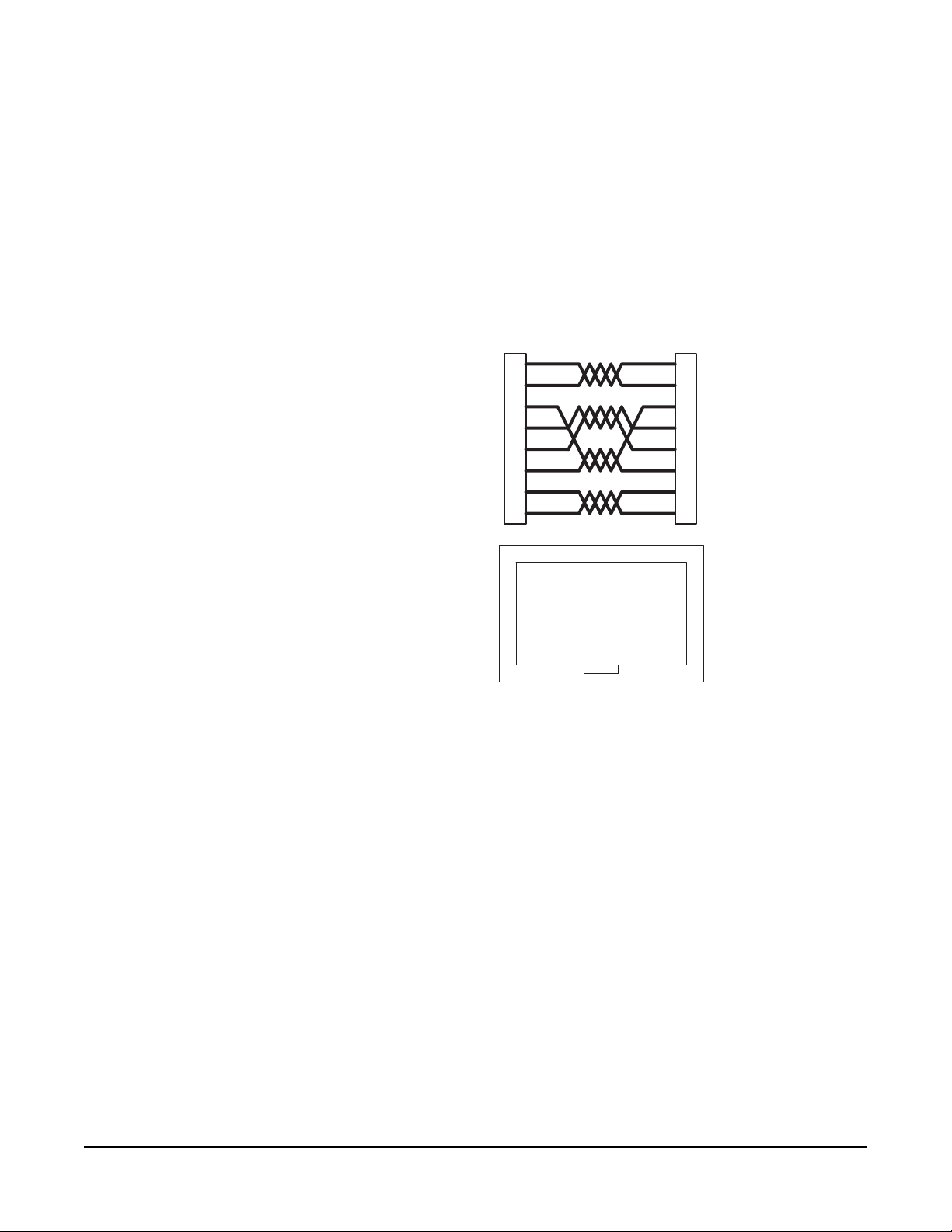
The FOR-22 interface connects to an Eclipse matrix through the two RJ-45
connectors on the IMF-3 or IMF-102 rear-panel assembly to which the FOR-22
unit is connected. One RJ-45 connector is for the first channel of the interface.
The second RJ-45 connector is for the second channel. Figure 3 shows pin
assignments of the RJ-45 connectors used to connect the interface to an Eclipse
matrix.
Figure 3: Matrix to Interface Frame Wiring
The "user" side of the FOR-22 for each channel is on a DB-9M connector on the
rear of the IMF-3 or IMF-102 frame. Figure 4 shows the pinout of either one of
these connectors. Each channel is identical.
The following sections describe how to wire for the various type of inputs and
outputs available on this connector:
• External Audio Devices
• Call Signal Input
• Relay Contacts
1
2
3
4
5
6
7
8
Matrix Frame End
Call Receive +
Call Receive -
Audio Receive +
Audio Send +
Audio Send -
Audio Receive -
Call Send +
Call Send -
Call Send +
Call Send -
Audio Send +
Audio Receive +
Audio Receive -
Audio Send -
Call Receive +
Call Receive -
Interface End
ATT-T568B (Modular Jumpers Wired One to One)
Pair 2
Pair 1
Pair 3
Pair 4
Interface Wiring
1 2 3 4 5 6 7 8
Rear View of
Connector
1
2
3
4
5
6
7
8

FOR-22 4-WIRE INTERFACE
2-6
Figure 4: Pinout of the DB-9M I/O Connectors for FOR-22s
EXTERNAL AUDIO DEVICES
Connect external audio devices to the FOR-22 ports through the two DB-9M
connectors labeled "I/O" on the rear panel assembly panel. Both audio input
and output are transformer isolated. Refer to Fig. 4 for pinouts.
CALL SIGNAL INPUT
The Call Signal input is used to receive a "call signal" or logic input from an
external device and send it to the matrix. The voltage across the pins required to
receive a call signal ranges from 4 Volts to 50 volts; it can be either positive or
negative polarity or AC. The input will draw between 4 and 8 milliamps. Refer
to Figure 4 for pinouts.
RELAY CONTACTS
Each FOR-22 channel features a relay that is associated with the logical "call
signal" output of a port. A relay's function depends on the function assigned to
the FOR-22 port in the configuration software. A relay can be assigned to
operate with any label in the system: when that label is activated (either by a talk,
listen, or both as set from the configuration program), the relay will be activated.
Or it can be assigned to be activated by a call signal, for example to operate a
2-way radio transmitter.
You can use the relay to activate an external device, such as an applause light in a
studio, a cue light, or a security door lock. The relays feature both "normally
open" and "normally closed" contacts. The contacts are rated at 1 Amp at 24
volts DC; they are not designed for switching mains AC line voltage. Refer to
Figure 4 for pinouts.
Audio Input
Logic Input (+/- 4 to 50 V)
Relay Normally Open
Audio Output
Audio Output
Audio Input
Relay Normally Closed
Relay Wiper
FOR-22 I/O DB-9M
Logic Input (+/- 4 to 50 V)
1
2
9
8
7
6
5
4
3

FOR-22 4-WIRE INTERFACE 2-7
ADJUSTMENTS
After installation the front-panel controls should be set to accommodate the
normal range of input and output levels encountered. The following is a
discussion of the controls and indicators on the front of the interface.
"Send Level" Control
The "send level" control allows adjustment of the output level of the channel
from the matrix to the external device/system.
"Send Level" LED
The 2-color "send level" LED lights green when an audio signal is being sent to
the external device or system at a typical acceptable level. The LED lights red
when the audio output signal level is too high.
"Recv" Control
The "recv" ("receive") level controls affect the level of signals sent from external
devices or system to the matrix. The "recv" controls have a range of ± 10 dB.
Relay Active LED
The yellow "relay" LED lights whenever the relay is activated. Intermittent fast
blinking on this LED is normal.
CONFIGURATION
You configure a central matrix port to work with the FOR-22 interface by setting
parameters in the Eclipse Configuration System (ECS) programming software.
Refer to the Eclipse Configuration System Instruction Manual for more
information.

FOR-22 4-WIRE INTERFACE
2-8

FOR-22 4-WIRE INTERFACE 3-1
MAINTENANCE
This chapter provides schematics, assembly drawings, and component lists for
the FOR-22 dual 4-wire interface module.
ASSEMBLY DRAWING FOR FOR-22 MODULE PCB
Figure 1: Assembly Drawing for FOR-22 Main Board PCB, Rev. B
3

FOR-22 4-WIRE INTERFACE
3-2
BILL OF MATERIALS FOR FOR-22 MODULE PCB
Component Part Component Description Qty Designator
151118 33PF 50V 5% NPO SMD 0805 12 C103,C105,C107,C110,C115,
C119,C203,C205,C207,C210,
C215,C219
151172 .1UF 50V 10% X7R SMD 0805 12 C104,C106,C111,C114,C117,
C118,C204,C206,C211,C214,
C217,C218
151176 .22UF 50V 10% X7R SMD 1210 6 C101,C102,C109,C201,C202,
C209
151200 22UF ALU 50V 20% SMD 8X6MM 2 C113,C112
170318 FOR-22 MAIN SMT PCB FAB 1
210174 EURO CARD RT ANG CONN 64
PIN M
1 J1
210226 JUMP JACK .1IN WITH HANDLE 2 JP100,JP200
210230 7 PIN DUAL ROW SOCKET
SPECIAL
1 J2
210273 DUAL ROW HEADER 3 POS
.230IN
2 JP200,JP100
240058 PIHER TRIMPOT SHAFT #5116
BLAC
4 P101,P102,P201,P202
280255 RIVET AVDEL #1189-2510 2 J1(2)
390029 T1 RT ANG PC MTG 5mA AMBER
LED
2 LED101,LED201
411197 10.0 1/10W 1% SMD 0805 4 R110,R122,R123,R210
411269 56.2 1/10W 1% SMD 0805 4 R118,R119,R218,R219
411285 82.5 1/10W 1% SMD 0805 2 R125,R225
411293 100 1/10W 1% SMD 0805 2 R115,R215
411310 150 1/10W 1% SMD 0805 2 R229,R129
411326 221 1/10W 1% SMD 0805 2 R109,R209
411389 1.00K 1/10W 1% SMD 0805 2 R130,R230
411431 2.74K 1/10W 1% SMD 0805 2 R208,R108
411454 4.75K 1/10W 1% SMD 0805 6 R120,R121,R124,R220,R221,
R224
411485 10.0K 1/10W 1% SMD 0805 18 R105,R106,R114,R116,R117,
R126,R127,R131,R132,R205,
R206,R214,R216,R217,R226,
R227,R231,R232
411527 27.4K 1/10W 1% SMD 0805 8 R101,R102,R103,R104,R201,
R202,R203,R204
411550 47.5K 1/10W 1% SMD 0805 2 R228,R128
450006 SPDT 12V MINI PC RELAY
ITT#SZ1
2 RL101,RL201
470059 50K TRIMPOT PIHER#PT10WH-
50K
4 P101,P102,P201,P202
481019 BAV70 DUAL DIODE COMMON
CATHOD
2 D201,D101
481020 BAW56 DUAL DIODE COMMON
ANODE.
4 D103,D104,D203,D204
481023 833 DUAL OPAMP... SOIC8 6 IC101,IC102,IC104,IC201,
IC202,IC204
481026 PMBT2222A NPN 40V 600MA
SOT-23
4 Q101,Q103,Q201,Q203
481032 M0C211 OPTOCOUPLER... S0IC8 2 IC203,IC103
FOR-22 4-WIRE INTERFACE 3-3
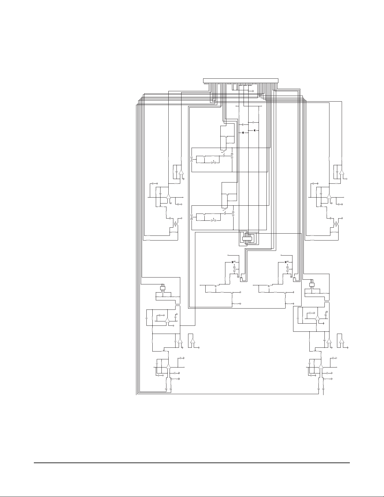
SCHEMATIC FOR FOR-22 MODULE PCB
Figure 2: Schematic for FOR-22 Main Board PCB, Rev. B
+
TO
MATRIX
FROM
IFB
CALL
RECEIVE
4-50VDC EITHER
POLARITY
4-8mA
IFB
MIC
LINE
SEND
MATRIX
CALL
CALL
RECEIVE
CW
MIC
CW
LINE
CCW
MATRIX
4-50VDC EITHER
POLARITY
TO
FOR CALL LOGIC
RECEIVE
FOR CALL LOGIC
RECEIVE
+
4-8mA
CCW
RECEIVE
MATRIX
CW
RECEIVE
CCW
* R113
NOT
LOADED
TO
MATRIX SEND
FROM
CCW
CW
*R213
NOT
LOADED
CHANNEL
A
CHANNEL
B
CHANNEL
A
CHANNEL
B
TO LEVEL
DETECT
PCB
SEND
SEND
CALL
CH. A
CH. B
CH. A CH. B
TO
MATRIX
-8V
+8V
+8V
-8V
+8V
-8V
+8V
-8V
+8V
-8V
-8V
+8V
-8V
+8V
+8V
-8V
-8V
+8V
T102
AUDIO 10K : 10K
1
6
5
3
4
2
JP100
LEVEL SELECT JUMPER
1
3
5
2
4
6
+
+
+
+
+
+
C111
.1 uF
12
Q104
MMBTA56
R132
10.0K
1 2
R212
0
12
R109
221
12
C219
33 pF
1 2
R111
0
12
R112
0
12
C205
33 pF
1 2
R113
*
12
R121
4.75K
1 2
R124
4.75K
1 2
C215 33 pF
1 2
R117
10.0K
1 2
R115
100
1 2
+
-
IC104B
LM833
5
6
7
D103
BAW56
1 2
3
P102
50K
13
2
R221
4.75K
1 2
R204
27.4K
1 2
C102
.22 uF
1 2
D203
BAW56
1 2
3
Q204
MMBTA56
IC203
MOC211
12
5 6
7
R213
*
12
C117
.1 uF
12
C113
22uF
35V
12
+
-
IC101A
LM833
3
2
1
84
R106
10.0K
1 2
C110
33 pF
1 2
R118
56.2
1 2
R125
82.5
1 2
D102
BAV99
12
3
C207
33 pF
1 2
C101
.22 uF
1 2
R101
27.4K
1 2
..
T201
AUDIO 600 : 600
211
5 8
C218
.1 uF
1 2
+
-
IC101B
LM833
5
6
7
C211
.1 uF
12
R208
2.74K
12
Q201
MMBT2222A
3
1
2
D201 BAV70
12
3
JP200
LEVEL SELECT JUMPER
1
3
5
2
4
6
+
+
+
+
+
+
R203
27.4K
1 2
R224
4.75K
1 2
C107
33 pF
1 2
R228
47.5K
12
LED101
AMBER
21
R215
100
1 2
R220
4.75K
1 2
+
-
IC201A
LM833
3
2
1
84
R229
150
1 2
RL101
1
4
3
2
5
..
T101
AUDIO 600 : 600
211
5 8
C202
.22 uF
1 2
R211
0
12
D2
GF1A
2 1
R103
27.4K
1 2
+
-
IC102A
LM833 SOIC
3
2
1
84
C209
.22 uF
12
R110
10.0
12
R102
27.4K
1 2
Q202
MMBT5551
3
1
2
R120
4.75K
1 2
R205
10.0K
1 2
R219
56.2
1 2
R227
10.0K
1 2
+
-
IC202B
LM833
5
6
7
R209
221
12
D104
BAW56
1 2
3
J1
EURO 64 M
1A
1C
2A
2C
3A
3C
4A
4C
5A
5C
6A
6C
7A
7C
8A
8C
9A
9C
10A
10C
11A
11C
12A
12C
13A
13C
14A
14C
15A
15C
16A
16C
17A
17C
18A
18C
19A
19C
20A
20C
21A
21C
22A
22C
23A
23C
24A
24C
25A
25C
26A
26C
27A
27C
28A
28C
29A
30A
30C
31A
31C
32A
32C
29C
R104
27.4K
1 2
R225
82.5
1 2
R105
10.0K
1 2
R126
10.0K
1 2
+
-
IC204B
LM833
5
6
7
C204
.1 uF
12
J2
1
3
5
7
9
11
13
2
4
6
8
10
12
14
+
+
+
+
+
+
+
+
+
+
+
+
+
+
Q101
MMBT2222A
3
1
2
+
-
IC201B
LM833
5
6
7
R231
10.0K
1 2
C106
.1 uF
12
C214
.1 uF
12
Q102
MMBT5551
3
1
2
P202
50K
13
2
C217
.1 uF
12
C203
33 pF
12
R226
10.0K
1 2
Q103
MMBT2222A
3
1
2
C104
.1 uF
12
R130
1.00k
1 2
R201
27.4K
1 2
D101 BAV 70
12
3
R202
27.4K
1 2
C112
22uF
35V
12
D202
BAV99
12
3
C118
.1 uF
1 2
RL201
1
4
3
2
5
R131
10.0K
1 2
R123
10.0
12
T202
AUDIO 10K : 10K
1
6
5
3
4
2
+
-
IC202A
LM833
3
2
1
84
R108
2.74K
12
C103
33 pF
12
+
-
IC204A
LM833
3
2
1
84
+
-
IC102B
LM833
5
6
7
R128
47.5K
12
LED201
AMBER
21
R232
10.0K
1 2
C210
33 pF
1 2
IC103
MOC211
12
5 6
7
R230
1.00k
1 2
C115 33 pF
1 2
R129
150
1 2
Q203
MMBT2222A
3
1
2
R218
56.2
1 2
C119
33 pF
1 2
R122
10.0
12
R114
10.0K
1 2
R116
10.0K
1 2
R206
10.0K
1 2
R127
10.0K
1 2
C206
.1 uF
12
+
-
IC104A
LM833
3
2
1
84
D1
GF1A
2 1
P101
50K
13
2
C105
33 pF
1 2
R217
10.0K
1 2
R214
10.0K
1 2
C201
.22 uF
1 2
C114
.1 uF
12
D204
BAW56
1 2
3
R119
56.2
1 2
C109
.22 uF
12
P201
50K
13
2
R210
10.0
12
R216
10.0K
1 2
FOR-22 4-WIRE INTERFACE
3-4
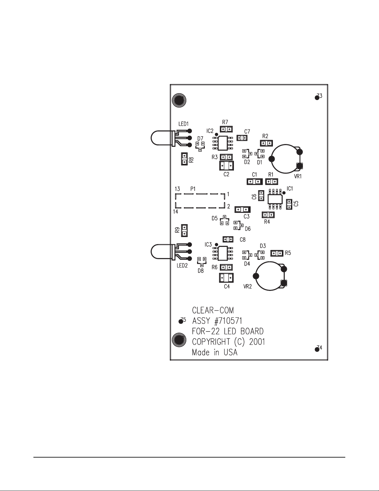
ASSEMBLY DRAWING FOR FOR-22 LEVEL DETECT
PCB
Figure 3: Assembly Drawing for FOR-22 Level Detect PCB, Rev. B
Table of contents
Other Clear-Com Recording Equipment manuals

Clear-Com
Clear-Com Encore TW-47 User manual

Clear-Com
Clear-Com ECLIPSE MATRIX User manual

Clear-Com
Clear-Com CCI-22 User manual

Clear-Com
Clear-Com PL-PRO EF-1M User manual

Clear-Com
Clear-Com LQ series User manual

Clear-Com
Clear-Com FIM-108 User manual

Clear-Com
Clear-Com ECLIPSE AES-6 User manual

Clear-Com
Clear-Com LQ series User manual

Clear-Com
Clear-Com RS-100A Troubleshooting guide

Clear-Com
Clear-Com Eclipse 13.1 HX User manual


