aci PIDS3 User manual

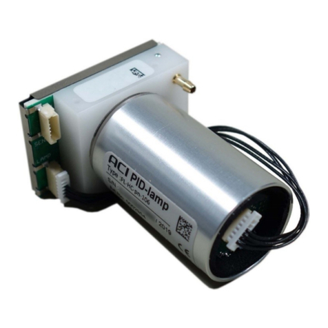
Smart Photoionization Detector Module PIDS3
User Manual
PIDS3 - User Manual (en) - 1.03.docx
Analytical Control Instruments GmbH, Volmerstraße 9A, 12489 Berlin, Germany, www.aci-berlin.com
Page 1 of 58
Smart Photoionization Detector Module
PIDS3
User Manual
from software version: 1.01.002

Smart Photoionization Detector Module PIDS3
User Manual
PIDS3 - User Manual (en) - 1.03.docx
Analytical Control Instruments GmbH, Volmerstraße 9A, 12489 Berlin, Germany, www.aci-berlin.com
Page 2 of 58
Analytical Control Instruments GmbH
Volmerstraße 9A
D-12489 Berlin
Germany
© Analytical Control Instruments GmbH. All rights reserved.

Smart Photoionization Detector Module PIDS3
User Manual
PIDS3 - User Manual (en) - 1.03.docx
Analytical Control Instruments GmbH, Volmerstraße 9A, 12489 Berlin, Germany, www.aci-berlin.com
Page 3 of 58
EU-Konformitätserklärung / EU-Declaration of conformity
Der Hersteller oder sein in der Gemeinschaft niedergelassener Bevollmächtigter /
The manufacturer or the European Authorized Representative:
Analytical Control Instruments GmbH
Volmerstraße 9A
D-12489 Berlin
Germany
erklärt hiermit, dass das Produkt / declares that the product:
Smart Photoionization Detector Module Version 3
Artikelnummer / Part No.:
0003143
Dieses Produkt erfüllt die Bestimmungen der Richtlinie 2014/30/EG (elektromagnetische Verträglichkeit) / This product is in conformance with the
EMC-Directive 2014/30/EU (electromagnetic compatibility):
Normen / Harmonized standards:
EN 50270:2015 –evaluation criteria “B”
Analytical Control Instruments GmbH
Dipl.-Ing. Andreas Otto
Managing Director
Berlin, March 2023

Smart Photoionization Detector Module PIDS3
User Manual
PIDS3 - User Manual (en) - 1.03.docx
Analytical Control Instruments GmbH, Volmerstraße 9A, 12489 Berlin, Germany, www.aci-berlin.com
Page 4 of 58
1Content
2 General.........................................................................................................................................................6
2.1 Correct Use ..........................................................................................................................................6
2.2 Liability Information.............................................................................................................................7
2.3 Safety and Precautionary Measures to be adopted ............................................................................7
2.4 Permanent Instrument Warranty ........................................................................................................7
3 Safety and Usage Instructions......................................................................................................................9
3.1 Terms and Symbols..............................................................................................................................9
4 Technical data............................................................................................................................................10
5 Safety and usage instructions ....................................................................................................................11
5.1 Terms and Symbols............................................................................................................................11
5.2 Correct use.........................................................................................................................................12
5.3 Liability Information...........................................................................................................................12
5.4 Safety and Precautionary Measures to be adopted. .........................................................................13
5.5 Permanent Instrument Warranty ......................................................................................................14
6 Smart Photoionization Detector Modul PIDS3 briefly ...............................................................................15
6.1 Installation .........................................................................................................................................16
6.2 Mechanical Installation......................................................................................................................17
6.3 Electrical Installation..........................................................................................................................18
6.4 Gas supply..........................................................................................................................................20
6.4.1 Using the internal optional pump..............................................................................................20
6.4.2 Using external pump..................................................................................................................21
6.4.3 Using without pump...................................................................................................................21
7 Installation hints ........................................................................................................................................22
8 Operation...................................................................................................................................................23
8.1 Using the module...............................................................................................................................23
8.2 Measurement values .........................................................................................................................25
8.3 Measurement result resolution.........................................................................................................25
9 Measurement config..................................................................................................................................27
9.1 Calibration method............................................................................................................................27
9.2 Gas identification and response factor..............................................................................................27
10 Calibration..............................................................................................................................................28
11 UART Communication............................................................................................................................31
11.1 Message frame...................................................................................................................................32
11.1.1 Checksum calculation.................................................................................................................33

Smart Photoionization Detector Module PIDS3
User Manual
PIDS3 - User Manual (en) - 1.03.docx
Analytical Control Instruments GmbH, Volmerstraße 9A, 12489 Berlin, Germany, www.aci-berlin.com
Page 5 of 58
11.1.2 Message section format.............................................................................................................34
11.2 Module commands ............................................................................................................................35
11.2.1 Module information commands................................................................................................35
11.2.2 Module control commands........................................................................................................36
11.2.3 Module data commands............................................................................................................37
11.2.4 Module Modbus config commands ...........................................................................................40
11.2.5 Module current loop config commands ....................................................................................40
11.2.6 Module autostart config commands..........................................................................................40
11.2.7 Module save config data command...........................................................................................41
11.2.8 Module relays commands..........................................................................................................41
11.2.9 Module lamp commands ...........................................................................................................42
11.2.10 Module sensor commands.....................................................................................................42
12 Modbus Communication .......................................................................................................................43
12.1 Register map ......................................................................................................................................43
12.1.1 Module information register .....................................................................................................43
12.1.2 Module measurement values data registers .............................................................................44
13 Current loop...........................................................................................................................................46
13.1 Connection.........................................................................................................................................46
13.2 Signals and states...............................................................................................................................47
13.3 Configurate measurement range.......................................................................................................47
14 Mechanical Drawing ..............................................................................................................................49
15 Maintenance and Service.......................................................................................................................50
15.2 How To –Replace the PID lamp/front isolation/sensor block...........................................................51
15.3 How To –Clean the PID Lamp............................................................................................................53
15.4 Maintenance Intervals .......................................................................................................................53
16 Ordering information.............................................................................................................................54
16.1 Photoionization Detector Module PIDS3...........................................................................................54
16.2 Type Definition...................................................................................................................................54
17 Spare parts and Accessories ..................................................................................................................55
18 Contact...................................................................................................................................................58

Smart Photoionization Detector Module PIDS3
User Manual
PIDS3 - User Manual (en) - 1.03.docx
Analytical Control Instruments GmbH, Volmerstraße 9A, 12489 Berlin, Germany, www.aci-berlin.com
Page 6 of 58
2General
The company Analytical Control Instruments GmbH (hereinafter the 'manufacturer') provides with the Smart
Photoionization Detector Module PIDS3 (hereinafter the 'module') a complete photoionization detector as a
closed module.
The module detects volatile organic compounds (VOC) with an ionization potential < 10.6 eV in air*.
Other ionization sources are available.
The ionization source is a high-performance vacuum ultraviolet (VUV) hollow cathode lamp with an energy
of 10.6 eV. With its ceramic discharge channel, the stability is improved and a longer service life of up to
15 000 hours and more will be achieved.
With its built-in electronics and microcontroller as well as a combined humidity/temperature sensor, it
provides a flexible and easy to use adaptation into your measurement system. The module comes with a
built-in linearization and temperature/humidity compensation. Built-in barometric pressure sensors offer
later compensation and gas flow monitoring.
The RS485 interface allows additional flexibility to choose the right interface for industrial and laboratory
applications. The optional analog 4 …20 mA output represents the linearized and compensated
concentration value in different scaling.
The module is available in different measurement ranges, with optional included pump and 4 …20 mA
output and MODBUS.
2.1 Correct Use
The device is suitable for outdoor and indoor applications that do not requires explosion protection, e.g.
offshore industry, chemical and petrochemical industry, water and sewage industry. The device comes in a
robust enclosure with dust and water protection.
It is imperative that this user manual be read and observed when using the product. In particular, the safety
instructions, as well as the information for the use and operation of the product, must be carefully read and
observed. Furthermore, the national regulations applicable in the user´s country must be considered for a
safe use.
WARNING
This product is supporting life and health. Inappropriate use, maintenance or servicing may
affect the function of the device and thereby seriously compromise the user`s life.
Before use, the product operability must be verified. The product must not be used if the
function test is unsuccessful, it is damaged, a competent servicing/maintenance has not
been made, genuine manufacturer spare parts have not been used.
Alternative use or use outside this specification will be considered as non-compliance. This also applies
especially to unauthorized alterations to the product and to commissioning work that has not been carried
out by manufacturer or authorized persons.

Smart Photoionization Detector Module PIDS3
User Manual
PIDS3 - User Manual (en) - 1.03.docx
Analytical Control Instruments GmbH, Volmerstraße 9A, 12489 Berlin, Germany, www.aci-berlin.com
Page 7 of 58
2.2 Liability Information
The manufacturer accepts no liability in cases where the product has been used inappropriately or not as
intended. The selection and use of the product are the exclusive responsibility of the individual operator.
Product liability claims, warranties also as guarantees made by manufacturer with respect to the product are
voided, if it is not used, serviced, or maintained in accordance with the instructions in this manual.
2.3 Safety and Precautionary Measures to be adopted
WARNING
The following safety instructions must be observed implicitly. Only in this way can the
safety and health of the individual operators, and the correct functioning of the
instrument, be guaranteed.
•The device described in this manual must be installed, operated, and maintained in strict accordance
with their labels, cautions, instructions, and within the limitations stated.
•The device is designed to detect volatile organic compounds or vapors in air.
•Do not mount the device in direct sunlight as this could cause overheating of the sensor.
•The device must be installed vertical with cable gland and the filter port unit downward to avoid
plugging of the gas inlets by particles or liquids.
•The only absolute method to ensure proper overall operation of the device is to check it with a known
concentration of the gas for which it has been calibrated. Consequently, calibration checks must be
included as part of the routine inspection of the system.
•As with all devices of these types, high levels of, or long exposure to, certain compounds in the tested
atmosphere could contaminate the sensor. In atmospheres where the device may be exposed to such
materials, calibration must be performed frequently to ensure that the operation is dependable and
display indications are accurate.
•Use only genuine manufacturer replacement parts when performing any maintenance procedures
provided in this manual. Failure to do so may seriously impair instrument performance. Repair or
alteration of the device, beyond the scope of these maintenance instructions or by anyone other than an
authorized manufacturer service personnel, could cause the product to fail to perform as designed.
•The device is designed for applications in hazardous areas under atmospheric conditions.
•Significant dust deposits on the gas inlets will increase the response time of the device. Checks for dust
deposits must be done at regular intervals.
2.4 Permanent Instrument Warranty
Warranty
Seller warrants that this product is designed and manufactured to the latest internationally recognized
standards by manufacturer under a quality management system that is certified to ISO 9001. As such the
manufacturer warrants that this product will be free from defective parts and workmanship and will repair
or (at its option) replace any instruments which are or may become defective under proper use within
twenty-four [24] months from date of commissioning by an approved manufacturer representative. This
warranty does not cover wearing parts,
i.e., parts inside the gas way like valves, pumps, lamp and other or damage caused by accident, abuse or
abnormal operating conditions.
Defective goods must be returned to manufacturer premises accompanied by a detailed description of any
issue. Where return of goods is not practicable manufacturer reserves the right to charge for any site
attendance where any fault is not found with the equipment. Manufacturer shall not be liable for any loss or

Smart Photoionization Detector Module PIDS3
User Manual
PIDS3 - User Manual (en) - 1.03.docx
Analytical Control Instruments GmbH, Volmerstraße 9A, 12489 Berlin, Germany, www.aci-berlin.com
Page 8 of 58
damage whatsoever or howsoever occasioned which may be a direct or indirect result of the use or
operation of the Contract Goods by the Buyer or any Party.
This warranty covers instrument and parts sold to the buyer only by authorized distributors, dealers and
representatives as appointed by manufacturer. The warranties set out in this clause are not pro rata, i.e. the
initial warranty period is not extended by virtue of any works carried out there under.
In no event will manufacturer be liable for any incidental damages, consequential damages, special
damages, punitive damages, statutory damages, indirect damages, loss of profits, loss of revenues, or loss of
use, even if informed of the possibility of such damages. Manufacturer is liability for any claims arising out of
or related to this product will in no case exceed the order value. To the extent permitted by applicable law,
these limitations and exclusions will apply regardless of whether liability arises from breach of contract,
warranty, tort (including but not limited to negligence), by operation of law, or otherwise.

Smart Photoionization Detector Module PIDS3
User Manual
PIDS3 - User Manual (en) - 1.03.docx
Analytical Control Instruments GmbH, Volmerstraße 9A, 12489 Berlin, Germany, www.aci-berlin.com
Page 9 of 58
3Safety and Usage Instructions
3.1 Terms and Symbols
In this manual, certain common terms and symbols used to warn you of dangers or to give you cautions that
are important in avoiding injury or damage. Observe and follow these cautions and regulations to avoid
accidents and damage. These terms and symbols explained below.
DANGER
Indicates a hazardous situation, which, if not avoided, WILL result in death or serious injury.
WARNING
Indicates a hazardous situation, which, if not avoided, COULD result in death of serious injury.
CAUTION
Indicates a hazardous situation, which, if not avoided, MAY in minor or moderate injury.
NOTICE
Indicates a property damage message.
Usage
Indicates a helpful information, hints or recommendation.

Smart Photoionization Detector Module PIDS3
User Manual
PIDS3 - User Manual (en) - 1.03.docx
Analytical Control Instruments GmbH, Volmerstraße 9A, 12489 Berlin, Germany, www.aci-berlin.com
Page 10 of 58
4Technical data
*
The indicated values were obtained under standardized conditions with 10.6 eV lamp.
Test gas was Isobutene in synthetic air.
Detector principle
VUV-Photoionization with 10.6 eV hollow cathode lamp
with Ceramic Discharge Channel technology and integrated high voltage supply.
(optional 11.8 eV and 10.0 eV lamp available)
Detection ranges
R0 –0 …2 000 ppm Isobutene *
R1 –0 … 20 ppm Isobutene *
R2 –0 … 5 000 ppm Isobutene *
Lower detection limit
R0 –typical 10 ppb *
R1 –typical 1 ppb *
R2 –typical 1 ppm*
Signal resolution
Dynamic up to 0.01 ppm (0.5 ppb at low range, 0.1 ppm at high range) or
raw precision with 3 digits (5 at low range, 2 at high range)
Response time
T90 < 10 s *
Signal integrity
Up to 100 ppm typical > 98 % *
Up to 5 000 ppm typical > 95 % *
Influence of humidity
Humidity and temperature compensation at 0 ... 60 °C and 0 …90 % rH
residual effect less than < 10 %
Operating conditions
-20 …+50 °C 0 …90 % rH, non-condensing
(-10 …+50 °C with integrated pump)
Storage conditions
-20 …+60 °C 0 …95 % rH, non-condensing
Gas flow
Required 200 …300 ml/min,
Sample inlet with dust and water protection filter
Optional with integrated pump available
Gas connection
Viton tube 1/8” ID (recommended)
Dust and water protection filter required
PID lamp lifetime
Min. 8 000 hours, typical more than 15 000 hours
Handling
Device configuration via RS485 UART
Digital interface
RS485 (UART or MODBUS) galvanic isolated
Analog interface
Current loop, 4 …20 mA (optional)
optional 3 SPDT 30 V / 2 A Relays (surge current)
Power supply
10.0 …28.0 VDC, max 1.5 W, recommended 24.0 VDC
Cable
Cable gland for cable diameter 5 mm … 9 mm
Screw connection inside
Conductor cross section solid max. 1.5 mm²
Conductor cross section stranded max. 1.5 mm²
Calibration
Two-point calibration
Ingress Protection
IP65 enclosure only, IP53 in operation due to gas inlet requirement
Dimension, weight
191 mm x 133 mm x 60 mm (L x W x H), about 1000 g
Warranty
2 years, except for components in gas path and wearing parts

Smart Photoionization Detector Module PIDS3
User Manual
PIDS3 - User Manual (en) - 1.03.docx
Analytical Control Instruments GmbH, Volmerstraße 9A, 12489 Berlin, Germany, www.aci-berlin.com
Page 11 of 58
5Safety and usage instructions
5.1 Terms and Symbols
In this manual, certain common terms and symbols are used to warn you of dangers or to give you cautions
that are important in avoiding injury or damage. Observe and follow these cautions and regulations to avoid
accidents and damage. These terms and symbols are explained below.
DANGER
Indicates a hazardous situation, which, if not avoided, WILL result in death or serious injury.
WARNING
Indicates a hazardous situation, which, if not avoided, COULD result in death or serious injury.
CAUTION
Indicates a hazardous situation, which, if not avoided, MAY result in minor or moderate
injury.
NOTICE
Indicates risk of property damage.
Usage
Indicates a helpful information, hint or recommendation.

Smart Photoionization Detector Module PIDS3
User Manual
PIDS3 - User Manual (en) - 1.03.docx
Analytical Control Instruments GmbH, Volmerstraße 9A, 12489 Berlin, Germany, www.aci-berlin.com
Page 12 of 58
5.2 Correct use
WARNING
This product may be supporting life and health. Inappropriate use, maintenance or servicing
may affect the function of the device and thereby seriously compromises the user`s life.
Before use, the product operability must be verified.
The product must not be used if the function test is unsuccessful, it is damaged, a competent
servicing/maintenance has not been made as required, genuine manufacturers spare parts
have not been used.
It is imperative to read this operating manual and observed when using the product. In particular, the safety
instructions, as well as the information for the use and operation of the product, must be carefully read and
observed. Furthermore, the national regulations applicable in the user´s country must be considered for a
safe use.
Alternative use or use outside this specification will be considered as non-compliance. This also applies
especially to unauthorized alterations to the product and to commissioning work that has not been carried
out by manufacturer or authorized persons.
5.3 Liability Information
The manufacturer accepts no liability in cases where the product has been used inappropriately or not as
intended or if seal is broken. The selection and use of the product are the exclusive responsibility of the
individual operator. Product liability claims, warranties also as guarantees made by the manufacturer with
respect to the product are voided, if it is not used, serviced, or maintained in accordance with the
instructions in this manual.

Smart Photoionization Detector Module PIDS3
User Manual
PIDS3 - User Manual (en) - 1.03.docx
Analytical Control Instruments GmbH, Volmerstraße 9A, 12489 Berlin, Germany, www.aci-berlin.com
Page 13 of 58
5.4 Safety and Precautionary Measures to be adopted.
WARNING
The following safety instructions must be observed implicitly. Only in this way can the safety
and health of the individual operators, and the correct functioning of the instrument, be
guaranteed.
•The module described in this manual must be installed, operated, and maintained in strict
accordance with their labels, cautions, instructions, and within the limitations stated.
•The module is designed to detect volatile organic compounds or vapors in air.
•The module is intended for installation in a higher-level device or as standalone instrument.
•The module must be installed in thermal isolated environment to achieve the full measurement
performance.
•The only absolute method to ensure proper overall operation of the device is to check it with a
known concentration of the gas for which it has been calibrated.
Consequently, calibration checks must be included as part of the routine inspection of the system.
•As with all modules of these types, high levels of, or long exposure to, certain compounds in the
tested atmosphere could contaminate the sensor. In atmospheres where the module may be
exposed to such materials, calibration must be performed frequently to ensure that the operation is
dependable and display indications are accurate.
•Use only genuine manufacture replacement parts when performing any maintenance procedures
provided in this manual. Failure to do so may seriously impair instrument performance. Repair or
alteration of the device, beyond the scope of these maintenance instructions or by anyone other
than an authorized manufacture service personnel, could cause the product to fail to perform as
designed.
•The module itself is NOT designed for applications in explosion hazardous areas.
•The functionality of the module will be influenced by pollution. Checks for dust deposits must be
done at regular intervals.

Smart Photoionization Detector Module PIDS3
User Manual
PIDS3 - User Manual (en) - 1.03.docx
Analytical Control Instruments GmbH, Volmerstraße 9A, 12489 Berlin, Germany, www.aci-berlin.com
Page 14 of 58
5.5 Permanent Instrument Warranty
Seller warrants that this product is designed and manufactured to the latest internationally recognized
standards by manufacturer under a quality management system that is certified to ISO 9001. As such the
manufacturer warrants that this product will be free from defective parts and workmanship and will repair
or (at its option) replace any instruments which are or may become defective under proper use within
twenty-four [24] months from date of commissioning by an approved manufacturer representative. This
warranty does not cover wearing parts, i.e., parts inside the gas way like lamp and sensor chamber or
damage caused by accident, abuse or abnormal operating conditions.
Defective module must be returned to manufacturer premises accompanied by a detailed description of any
issue. Where return of module is not practicable manufacturer reserves the right to charge for any site
attendance where any fault is not found with the equipment. Manufacturer shall not be liable for any loss or
damage whatsoever or howsoever occasioned which may be a direct or indirect result of the use or
operation of the contract goods by the buyer or any party.
This warranty covers modules and parts sold to the buyer only by authorized distributors, dealers and
representatives as appointed by manufacturer. The warranties set out in this clause are not pro rata, i.e., the
initial warranty period is not extended by virtue of any works carried out there under.
In no event will manufacturer be liable for any incidental damages, consequential damages, special
damages, punitive damages, statutory damages, indirect damages, loss of profits, loss of revenues, or loss of
use, even if informed of the possibility of such damages. Manufacturer is liability for any claims arising out of
or related to this product will in no case exceed the order value. To the extent permitted by applicable law,
these limitations and exclusions will apply regardless of whether liability arises from breach of contract,
warranty, tort (including but not limited to negligence), by operation of law, or otherwise.

Smart Photoionization Detector Module PIDS3
User Manual
PIDS3 - User Manual (en) - 1.03.docx
Analytical Control Instruments GmbH, Volmerstraße 9A, 12489 Berlin, Germany, www.aci-berlin.com
Page 15 of 58
6Smart Photoionization Detector Modul PIDS3 briefly
The inlet and outlet for gas and the cable gland are located at the following positions.
The sample gas will be conducted through the sample gas inlet. A glass-fiber syringe-filter protects the
device against material pollution.
Gas Inlet
Type
male luer
Fit to tube Inner diameter
3.0 mm to 3.5 mm
Gas Outlet
Type
thread hole M5
Fit to connectors with M5 thread
E.g., SMC M5-AU-3
CAUTION
Do not remove the filter for measurement this may damage the instrument.
Gas flow
Minimum
300 ml/min
Maximum
500 ml/min
Cable gland M 16 X 1,5
Minimum outer diameter
5 mm
Maximum outer diameter
9 mm

Smart Photoionization Detector Module PIDS3
User Manual
PIDS3 - User Manual (en) - 1.03.docx
Analytical Control Instruments GmbH, Volmerstraße 9A, 12489 Berlin, Germany, www.aci-berlin.com
Page 16 of 58
6.1 Installation
The device should be installed where gas leaks are expected. The installation position depends on the gas
density, either in the upper area of the room under the ceiling for gases lighter than air or close to the
ground for gases heavier than air. Also, consider how air movement may affect the ability of the device to
detect gas. The display on the front of the instrument must always be clearly visible; the view must not be
obstructed.
Before beginning the installation, check that the delivered components are complete and
correct referring to the shipping documents and the sticker on the shipment carton.
When preparing the assembly, make sure that the mounting arrangement is correct for the
device.

Smart Photoionization Detector Module PIDS3
User Manual
PIDS3 - User Manual (en) - 1.03.docx
Analytical Control Instruments GmbH, Volmerstraße 9A, 12489 Berlin, Germany, www.aci-berlin.com
Page 17 of 58
6.2 Mechanical Installation
Mounting
The housing of Smart PID module must be mounted at the following positions:
•Indoor, or inside housings with minimum splash water protection –arbitrary orientation.
•In all other cases –cable gland and gas ports downside (IP 54 rating).
The device must be installed vertical with cable glands and filter downward to avoid plugging
of the inlets by particles or liquids if can occur.

Smart Photoionization Detector Module PIDS3
User Manual
PIDS3 - User Manual (en) - 1.03.docx
Analytical Control Instruments GmbH, Volmerstraße 9A, 12489 Berlin, Germany, www.aci-berlin.com
Page 18 of 58
6.3 Electrical Installation
•Shielded cable for measuring devices is recommended.
•All cable shields to be terminated to ground earth at one end only.
•Water or impurities can penetrate the instrument through the cable. In hazardous areas, it is
recommended to install the cable in a loop just before entry into the instrument or to slightly bend it
to prevent water from entering.
NOTICE
The power supply is defined as 10 … 28 VDC.
How To –Install Electrical Connection
1. Open the device.
2. Unscrew clamping nut at the cable gland.
3. Put clamping nut on the cable. Prepare cable for installation, enable shield to connect with cable
gland.
4. Insert cable for connection into the device.
5. Tighten cable gland clamping nut including shield, check that cable cannot move within the cable
gland.
6. Connect cable to the corresponding pin numbers of the terminal.
7. Set up enclosure lid and the screws.
WARNING
The device must be installed only in compliance with the applicable regulations, otherwise
the safe operation of the instrument is not guaranteed.

Smart Photoionization Detector Module PIDS3
User Manual
PIDS3 - User Manual (en) - 1.03.docx
Analytical Control Instruments GmbH, Volmerstraße 9A, 12489 Berlin, Germany, www.aci-berlin.com
Page 19 of 58
X1
1
2
3
4
Power
V+ 24 VDC
CL 4 …20 mA
V- 0 VDC
SHIELD
[ Positive Supply ]
[ Current Loop Output ]
[ Negative Supply ]
[ for cable with add. inner shield ]
1
2
3
4
X2
1
2
3
RS485 (MODBUS)
A
GND
B
[ Non Inverting Terminal ]
[ Isolated Ground ]
[ Inverting Terminal ]
1
2
3
J1
COMM SELECT
Jumper plugged in
Jumper not
plugged
[ RS485 UART communication ]
[ RS485 MODBUS communication ]
Relays (optional)
X3
1
2
3
ERROR
Relay NC
Relay COM
Relay NO
[ Normally Closed De-Energized Contact ]
[ Common Contact ]
[ Normally Open De-Energized Contact ]
1
2
3
X4
1
2
3
ALARM HIGH
Relay NC
Relay COM
Relay NO
[ Normally Closed De-Energized Contact ]
[ Common Contact ]
[ Normally Open De-Energized Contact ]
1
2
3
X5
1
2
3
ALARM LOW
Relay NC
Relay COM
Relay NO
[ Normally Closed De-Energized Contact ]
[ Common Contact ]
[ Normally Open De-Energized Contact ]
1
2
3

Smart Photoionization Detector Module PIDS3
User Manual
PIDS3 - User Manual (en) - 1.03.docx
Analytical Control Instruments GmbH, Volmerstraße 9A, 12489 Berlin, Germany, www.aci-berlin.com
Page 20 of 58
6.4 Gas supply
NOTICE –WATCH THE GAS FLOW
The module requires a uniform gas flow.
Gas must be free of dust and liquids.
Dust and liquids must be kept away from module internal gas paths.
The module comes with an integrated gas flow monitoring. The current gas flow indicator can be read with
measurement values of UART command and Modbus data registers.
The module status information contains two flow indications:
•‘flow low’ - gas flow too low, measurement result integrity loss and module may be damaged
•‘flow over’ - gas flow too high, measurement result integrity loss
6.4.1 Using the internal optional pump
The internal optional pump ensures ambient measurement gas flow through the PID sensor.
For usage of a constant measurement gas source e.g., from a pressure line, the module gas input must be
bypassed.
NOTICE –WATCH THE GAS FLOW
Gas input must be nearly having ambient pressure (deviation recommended less than 20
mbar) in pump operation.
Constant flow from active gas source will need a bypass line for surplus measurement gas.
Gas source should support at least 400 ml/min to realize 200 to 300 ml/min flow in module.
Gas flow scheme with internal optional pump and constant flow of measurement gas source at gas input
PIDS MODULE
with optional pump
DUST AND WATER
PROTECTION FILTER
GAS
IN
GAS
OUT
at least 400 ml/min
MEASUREMENT
GAS ONLY SOURCE
Bypass out
This manual suits for next models
1
Table of contents
Other aci Control Unit manuals
Popular Control Unit manuals by other brands

Bray
Bray 19L Series Installation, operation and maintenance manual

ETAS
ETAS ES650.1 user guide

APARIAN
APARIAN J1939/B Series quick start guide
Carrier
Carrier 50CO Series Installation, operation and maintenance instructions

Honeywell
Honeywell S4567A 1001 instruction sheet
Vimar
Vimar Elvox RS15 Installation and operation manual
