OPERATION
Est blishing communic tion from the p nel
In order to establish communication, press the call button on the panel. If the called monitor is in the system, it will start
to ring (the call lasts for 45 s). Otherwise, the panel will generate a "busy" signal. During a call to a monitor, it is possible
to temporarily mute the ring by touching the – icon.
To receive a call, touch the telephone receiver icon. In the conversation mode, volume can be adjusted with + and –
icons. If a conversation is totally muted (the volume bar grayed out), the microphone in the monitor is switched off as
well. An established connection can last up to 4 minutes. After this period, it is terminated. The monitor has the function
of signalling an unreceived call from the panel. In case a call from the panel is not received, the monitor icon will blink.
The signal is cancelled by touching the icon.
Use of codes nd proximity keyc rds
In order to open the door (usually by activating the electric strike), the user should key in a correct code or bring
a proximity keycard close to the bottom field with a surname (by default, no keycards are registered in the device).
If a non-registered keycard is brought close to the device, the panel will generate a sequence of three sound signals.
It is easiest to manage codes and keycards with the Family PRO computer application. The following codes are factory-
set:
bottom button: 1111 (for address 1)
second button from the bottom: 2222 (for address 2)
third button from the bottom: 3333 (for address 3)
administrator's code: 4444
Attention! It is recommended to change all the codes, once the Panel has been installed.
If the key button is pressed before code keying or using a proximity keycard, an additional device is activated, e.g. a gate
(a special PRO-I/O module is required).
The user can modify codes in the following manner: Introduce the current code. Then, during 1.5 second, press and hold
the “key” button, until (after about 4 s) the panel will issue a single sound. Then, introduce the new four-digit code.
The panel will confirm with a sequence of three sound that it has been accepted.
Restoring factory-defined codes and adding/deleting keycards
It is possible to restore factory-defined opening codes and add/delete proximity keycards if “Block restoration of factory-
defined codes and keycards” option is not enabled. To do this, switch the panel power supply off, wait 5 seconds, press
the call button corresponding to the flat, which an ascribed code and cards are to be restored/deleted, switch the panel
power supply on, hold the button, until the panel issues a long continuous sound. After this operation, the panel will start
to generate a fast intermittent sound signal, which means that it has restored the factory-set code and entered the
keycard adding procedure (while deleting all the keycards that could have been ascribed before). If a keycard is applied
to the bottom surname field, when this sound is being issued (it lasts about 5 seconds), the panel will start to open the
door, which means that the first keycard (master) has been correctly read and recorded. If another unregistered card is
applied during 5 seconds after door opening, the panel will issue a short double sound signal – the next keycard has
been correctly read and recorded (if the keycard is held against the field for too long, the panel will start to open the door
again). After that, one can register other keycards. Up to 10 keycards can be ascribed to one flat (button). To finish the
keycard registration process, wait 5 seconds or press the “#” button. The keycard registration procedure will get
terminated. It is possible to restore the code and delete/add cards corresponding to the administrative account only with
the PC application.
Adding keyc rds by me ns of the “m ster” keyc rd”
very first keycard that is added to a particular flat and administrative account has the status of the “master” card that
can be used to add further cards. To do this, open the door with the master card and apply an unregistered card to the
field during 5 seconds after the door was opened. The panel will start to open the door again, which means the next
keycard has been correctly read and registered. The procedure is analogous to the one described above.
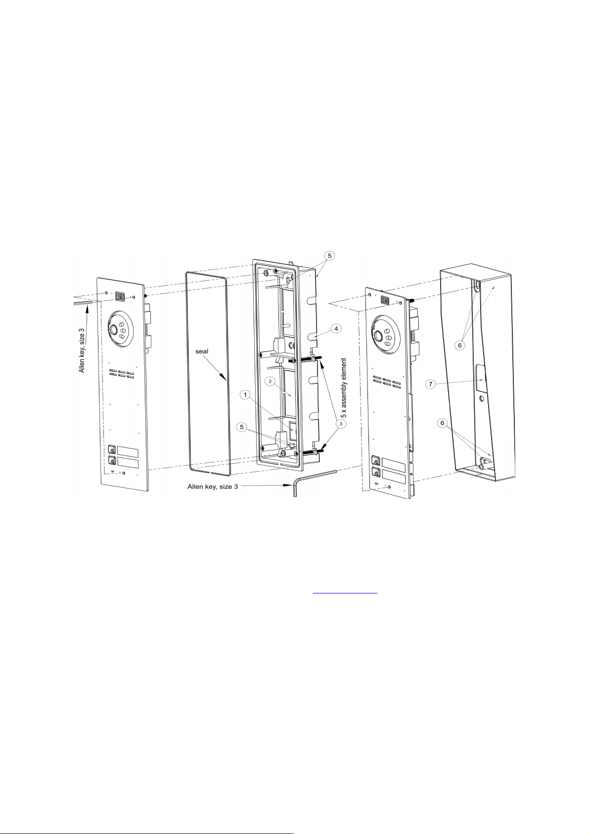
SYSTEM CONNECTION AND ASSEMBLY
The RJ45 jack should be crimped according to standard T568B. The signals on particular lines are presented in Fig. 4.1.
Before switching the power on, one should ensure th t ll the connections h ve been m de in compli nce with
the di gr m, th t RJ45 plugs re correctly crimped nd th t there re not short-circuits between c ble
conductors.
Fig. 4.1 Distribution of lines in RJ45 connector and description of terminals
It is recommended to use thernet twisted pair cable (UTP, at least category 5e) for system cabling, and to use at least
1.5 mm2 conductors to supply power to the electric strike, while keeping the distances indicated in Fig. 4.3. Panel
connections can be made interchangeably by means the RJ45 socket or screwed terminal connectors. lectric strike
power supply and control lines should be made of cables appropriate for the consumed current (typically 2x1.5 mm2).
In case RJ45 connector is used, twisted pair should be crimped as shown in Fig. 4.2. When screwed terminal connectors
are used, they should be made according to 4.2: power supply to +DC and GND terminals, the signal line to the LIN