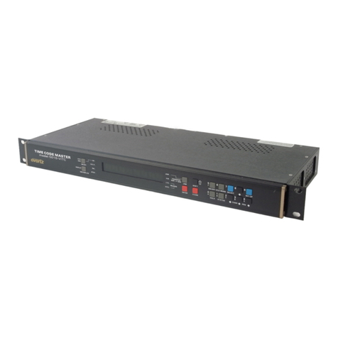
Acromag IOS-7200 User manual

IOS-7200
Industrial Computer with 500MHz AMD®Geode Processor
USER’S MANUAL
ACROMAG INCORPORATED Tel: (248) 295-0310
30765 South Wixom Road Fax: (248) 624-9234
Wixom, MI 48393-7037 U.S.A. Web: http://www.acromag.com
Copyright 2010-2011, Acromag, Inc., Printed in the USA.
Data and specifications are subject to change without notice. 8500-878-D13C009
retired

I/O SERVER User’s Manual Industrial PC
__________________________________________________________________
________________________________________________________________________
Acromag, Inc. Tel:248-295-0310 Fax:248-624-9234 Email:solutions@acromag.com http://www.acromag.com
2
IMPORTANT SAFETY CONSIDERATIONS
You must consider the possible negative effects of power, wiring,
component, sensor, or software failure in the design of any type of control
or monitoring system. This is very important where property loss or human
life is involved. It is important that you perform satisfactory overall system
design and it is agreed between you and Acromag, that this is your
responsibility.
1.0 General Information
KEY FEATURES………………………………………...
4
BOARD CONTROL SOFTWARE……………………..
5
SIGNAL INTERFACE PRODUCTS……………………
5
2.0 PREPARATION FOR USE
UNPACKING AND INSPECTION……………………..
6
BOARD CONFIGURATION…………………………….
6
Default Hardware Configuration……………….
6
IOS MODULE INSTALLATION………………………..
7
FRONT PANEL FIELD I/O CONNECTOR……………
8
10/100 Ethernet Connection…………………….
8
VGA Video Connection…………………………..
9
Serial Connections……………………………….
9
USB Ports…………………………………………..
10
Audio Jacks………………………………………..
10
IOS Modules Field I/O……………………………
11
REAR PANEL FIELD CONNECTORS………………..
11
CompactFlash®……………………………………
11
Power & LEDs……………………………………..
12
OPTIONAL 2.5” DRIVE…………………………………
12
2.5” IDE Drive Installation……………………….
12
NON-ISOLATION CONSIDERATIONS……………….
13
3.0 BIOS
MAIN MENU……………………………………………...
14
Passwords…………………………………………
15
STANDARD CMOS FEATURES………………………
16
ADVANCED BIOS FEATURES………………………..
17
ADVANCED CHIPSET FEATURES…………………..
19
INTEGRATED PERIPHERALS………………………..
20
POWER MANAGEMENT SETUP……………………..
21
PnP/PCI CONFIGURATIONS………………………….
22
PC HEALTH STATUS…………………………………..
22
BIOS RECOVERY PROCEDURE……………………..
23
TABLE OF
CONTENTS
The information in this manual
may change without notice.
Acromag makes no warranty
of any kind with regard to this
material, including, but not
limited to, the implied
warranties of merchantability
and fitness for a particular
purpose. Further, Acromag
assumes no responsibility for
any errors that may appear in
this manual and makes no
commitment to update, or
keep current, the information
contained in this manual. No
part of this manual may be
copied or reproduced in any
form without the prior written
consent of Acromag, Inc.

I/O SERVER User’s Manual Industrial PC
___________________________________________________________________
________________________________________________________________________
Acromag, Inc. Tel:248-295-0310 Fax:248-624-9234 Email:solutions@acromag.com http://www.acromag.com
3
4.0 SYSTEM OVERVIEW
I/O Server Internal Ethernet Switch…………………
24
I/O Server Power Supply Fuse……………………….
24
IDE (PATA) Hard Drive Connections………………..
24
MLC vs. SLC Flash……………………………………..
25
CARRIER BOARD OVERVIEW……………………….
25
PCI Bus Interface…………………………………
25
IOS Carrier Board Registers……………………
25
IOS Logic Interface……………………………….
26
IOS Carrier Board Clock Circuitry……………..
26
PCI Interrupts……………………………………...
26
IOS Modules Power-On Reset………………….
26
IOS Modules Power Supply Fuses…………….
26
5.0 ACCESSING THE IOS CARRIER
PCI Configuration Address Space…………………..
27
PCI Configurations Transactions……………………
27
PCI Configuration Registers………………………….
27
MEMORY MAP…………………………………………..
28
Carrier Status/Control Register………………..
30
IOS Interrupt Pending Register………………...
32
Clock Control Register…………………………..
32
IOS Module Interrupt Space…………………….
32
IOS Module ID Space…………………………….
33
IOS Module I/O Space……………………………
33
IOS Module Memory Space……………………..
33
GENERATING INTERRUPTS………………………….
33
6.0 SERVICE AND REPAIR
SERVICE AND REPAIR ASSISTANCE………………
34
PRELIMINARY SERVICE PROCEDURE…………….
34
WHERE TO GET HELP…………………………………
34
7.0 SPECIFICATIONS
PHYSICAL………………………………………………..
35
ELECTRICAL…………………………………………….
35
ENVIRONMENTAL……………………………………...
38
APPENDIX
IOS-7200 BLOCK DIAGRAM………………………….
40
IOS-CARRIER FUSE LOCATION DRAWING……….
41
SYSTEM I/O PORTS MEMORY MAP………………...
42
SYSTEM IRQ ASSIGNMENTS………………………..
43
SYSTEM 1MB MEMORY MAP………………………...
43
Trademarks are the property of their respective owners.
TABLE OF
CONTENTS

I/O SERVER User’s Manual Industrial PC
__________________________________________________________________
________________________________________________________________________
Acromag, Inc. Tel:248-295-0310 Fax:248-624-9234 Email:solutions@acromag.com http://www.acromag.com
4
The I/O Server Industrial computer provides users with a mobile rugged
computing option with a wide variety of integrated I/O connections. The
IOS-7200 has a built in 500MHz AMD®Geode processor with 512MB of
DDR RAM and features two Ethernet ports, four USB ports, audio, video,
and two COM ports. The I/O Server’s built in carrier card allows for users
to select up to four plug-in I/O modules that provide a wide range of
industrial input/output including digital, analog inputs, analog outputs,
counter-timer modules, and a module with a customer programmable
FPGA. All these items are packaged in a small rugged fanless form factor
with an extended operating temperature range. Refer to the table below
for available I/O Server models.
MODEL
Front I/O Type
Front I/O Connector
OPERATING
TEMPERATURE
RANGE
IOS-7200
AMD®Geode LX800 500MHz
512MB DDR
-30C to +75C
IOS-7400
Intel®Atom N270 1.6GHz
1GB DDR2
-30C to +75C
Both models are available with a -WIN suffix. These versions include an
8GB Industrial CompactFlash®with a Windows®Embedded Standard
image and license.
The I/O Server and IOS modules are suitable for use in Class I, Division 2,
Groups A, B, C, and D hazardous locations or non-hazardous locations
only.
The following models are the available IOS modules, which are cULus
listed and can only be used in the IOS-7200 & IOS-7400 I/O Server. All
IOS models operate at the full operating temperate of the base I/O Server
unit. Refer to the individual manuals for each of the IOS modules for
further information.
Models: IOS-220-8, IOS-220-16, IOS-231-8, IOS-231-16, IOS-320, IOS-
330, IOS-341, IOS-EP201, IOS-EP202, IOS-EP203, IOS-EP204, IOS-520,
IOS-521, IOS-560, IOS-560-I, IOS-571, IOS-572, IOS-408, IOS-409, IOS-
440-2, IOS-445, IOS-470, IOS-482, IOS-483, and IOS-484.
.
Rugged Embedded PC –The IOS-7200 includes an embedded
500MHz AMD®Geode processor with 512MB of installed DDR RAM.
This is a low power fanless design with high-reliability operation that is
shock and vibration resistant.
High-density, Interchangeable I/O –Each I/O server supports up to
four separate IOS module to enable mix and match flexibility for a wide
variety of field I/O.
Extended Temperature Range –The IOS-7200 has a wide operating
temperature range even with four IOS modules installed under a full
system load.
1.0 GENERAL
INFORMATION
Table 1.1: I/O Server Basic
Models
KEY FEATURES

I/O SERVER User’s Manual Industrial PC
___________________________________________________________________
________________________________________________________________________
Acromag, Inc. Tel:248-295-0310 Fax:248-624-9234 Email:solutions@acromag.com http://www.acromag.com
5
Standard Peripheral Connection –The I/O Server provides two
standard RS232 serial ports, two switched Ethernet ports, four USB,
audio, and video ports for peripheral connections.
Windows®Embedded Standard –The IOS-7200-WIN model includes
a Windows®Embedded Standard (based upon Windows®XP SP3)
image installed on an 8GB Industrial CompactFlash®.
Windows Drivers –The IOSSW-DEV-WIN software support package
contains low-level driver and Windows 32 Dynamic Link Libraries that
are compatible with many programming environments.
Linux Drivers –The IOSSW-API-LNX software support package
contains the Linux OS Getting Started Guide and IOS modules Linux
device drivers are available from Acromag.
Wide Operating Voltage –The I/O Server has a 9-32V DC input.
External isolated AC/DC power supplies are available from Acromag.
The IOS-7200-WIN model includes an 8GB industrial CompactFlash®
that contains a licensed Microsoft Windows®Embedded Standard image.
The image includes many of the standard Windows components and is
suitable for the majority of customer applications. This allows users to
quickly develop their application in a familiar environment. Device drivers
for Acromag IOS modules are sold separate as described in the following
section.
Acromag provides a software product (sold separately) to facilitate the
development of Windows®Embedded Standard applications interfacing
with I/O Server Modules installed on Acromag Industrial I/O Server
systems. This software (Model IOSSW-DEV-WIN) consists of low-level
driver and Windows 32 Dynamic Link Libraries (DLLS) that are compatible
with a number of programming environments including Visual C++, Visual
Basic.NET, Borland C++ Builder and others. The DLL functions provide a
high-level interface to the IOS carrier and modules eliminating the need to
perform low-level reads/writes of registers, and the writing of interrupt
handlers.
Acromag provides a software product (sold separately) consisting of
IOS module Linux support software. This software (Model IOSSW-API-
LNX) is composed of Linux libraries designed to support applications
accessing I/O Server Modules installed on Acromag Industrial I/O Server
systems. The software is implemented as a library of “C” functions which
link with existing user code.
Acromag provides the following interface products for the I/O Server.
Note that all connections to field signals are made through the IOS carrier
board which passes them to the individual IOS modules.
Model 5028-438: SCSI-2 50 Pin Shielded Cable. A round 50-pin cable
with SCSI-2 plug connectors at both ends for connecting I/O Server to
Model 5028-378 termination panels.
BOARD CONTROL
SOFTWARE
Windows®Embedded
Standard
IOS MODULE Win32 DRIVER
SOFTWARE
IOS MODULE LINUX
SOFTWARE
SIGNAL INTERFACE
PRODUCTS
CABLES

I/O SERVER User’s Manual Industrial PC
__________________________________________________________________
________________________________________________________________________
Acromag, Inc. Tel:248-295-0310 Fax:248-624-9234 Email:solutions@acromag.com http://www.acromag.com
6
Model 5028-378: DIN-rail mountable panel provides 50 screw terminals
for universal field I/O termination. Connects to Acromag IOS-7200 via
SCSI-2 50 pin shielded cable (Model 5028-438)
Upon receipt of this product, inspect the shipping carton for evidence of
mishandling during transit. If the shipping carton is badly damaged or
water stained, request that the carrier's agent be present when the carton
is opened. If the carrier's agent is absent when the carton is opened and
the contents of the carton are damaged, keep the carton and packing
material for the agent's inspection.
For repairs to a product damaged in shipment, refer to the Acromag
Service Policy to obtain return instructions. It is suggested that
salvageable shipping cartons and packing material be saved for future use
in the event the product must be shipped.
This board is physically protected with packing material. However, it is
recommended that the unit be visually inspected for evidence of
mishandling prior to applying power.
Refer to the specifications for loading and power requirements. Be sure
that the system power supplies are able to accommodate the power
requirements of the system board, plus the installed IOS modules, within
the voltage tolerances specified.
The I/O Server is designed to operate in areas with little or no air
circulation. However to facilitate conduction cooling of the unit, it must be
orientated such that heat fins are on top or the side of the device (in
reference to the floor). Orientating the object with the heat fins facing
downward may cause the internal temperature to rise above the maximum
operating temperature.
Remove power from the system before installing any IOS modules,
cables, and/or field wiring.
Upon receipt, customer can use the I/O Server once an appropriate
operating system has been installed.
WARNING –EXPLOSION HAZARD –Do not disconnect equipment
unless power has been removed or area the area is known to be non-
hazardous.
WARNING –EXPLOSION HAZARD –Substitution of any components
may impair suitability for Class I, Division 2.
WARNING –EXPLOSION HAZARD –The area must be known to be
non-hazardous before servicing/replacing the unit and before installing.
TERMINATION PANEL
Refer to Acromag’s website
www.acromag.com for more
information on compatible
products.
2.0 PREPARATION
FOR USE
UNPACKING AND
INSPECTION
ENVIRONMENTAL
CONSIDERATIONS
BOARD
CONFIGURATION
Default Hardware
Configuration
Warnings

I/O SERVER User’s Manual Industrial PC
___________________________________________________________________
________________________________________________________________________
Acromag, Inc. Tel:248-295-0310 Fax:248-624-9234 Email:solutions@acromag.com http://www.acromag.com
7
To install the IOS modules, first remove all power from the device. The
IOS Carrier is not hot swappable. Failure to power down the I/O Server
prior to removing the IOS carrier will result in board damage. To remove
the IOS Carrier turn the two Captive screws counterclockwise on the front
panel until they are free of the enclosure. Then pull the IOS Carrier out
from the enclosure. The IOS Carrier slides out on guide rails. Note that
some force is required to remove the IOS Carrier, especially if IOS
modules are already installed. Refer to the picture below.
Once the IOS Carrier has been removed install the IOS modules onto
the Carrier board. The modules are keyed to avoid incorrect installation.
No further hardware is required to secure the IOS modules. The four slots
are marked as A, B, C or D. Note the slot location of each module as this
information is necessary to access the IOS module from software. Refer to
Section 4.0 for further information on accessing the IOS modules.
IOS Module Installation
DANGER: The IOS Carrier is
NOT hot swappable. Power
must be removed from the
device before removing the
IOS Carrier.
Figure 2.1: IOS Carrier
Removal.
To remove the Carrier turn the
2 captive screws to the left
until they are detached from
the faceplate. Then pull out
the IOS carrier.
Figure 2.2a: IOS Module
Installation
To install the IOS Modules
firmly press them into any of
the four available slots. IOS
Modules are keyed to avoid
incorrect installation.
IOS Carrier
Captive Screws (2x)

I/O SERVER User’s Manual Industrial PC
__________________________________________________________________
________________________________________________________________________
Acromag, Inc. Tel:248-295-0310 Fax:248-624-9234 Email:solutions@acromag.com http://www.acromag.com
8
After IOS module installation, slide the IOS Carrier back into the
enclosure via the guide rails until the front panel is flush against the
faceplate. Note that considerable force is required to push the carrier and
the mating connector together. Once the panel is flush, turn the two
captive screws clockwise until tight.
The I/O Server front panel has many of the same connections as a
standard personal computer. This includes Ethernet, audio, video, USB,
and serial ports. Access to these ports is obtained though the Operating
System. The front panel also provides user access to the IOS carrier
board which contains the IOS modules as well as the corresponding I/O
connections (ports). Information regarding these ports is contained in the
following section.
There are two RJ45 10/100 Ethernet ports available on the front of the
I/O Server. These two ports connect to an internal three port switch. The
third port of the switch connects to the processor unit. The two external
ports can be used independently of the processor. Refer to the
specifications settings for further information on the Ethernet port settings.
The two Ethernet ports are shown below.
The pin outs for the Ethernet connector from left to right are numbered
one through eight in order. The upper left yellow LED on each port
indicates connection speed. A blinking yellow LED indicates a 10Mbps
connection while a solid yellow LED indicates a 100Mbps connection. The
upper right Green LED is solid when a link is established and blinks as
data is transferred.
Figure 2.2b: IOS Module
Installation
To install the IOS Modules
firmly press them into any of
the four available slots. IOS
Modules are keyed to avoid
incorrect installation.
Note: Inserting the IOS Carrier
may require considerable
force.
Front Panel Field I/O
Connector
10/100 Ethernet
Connection
Figure 2.3: Ethernet Ports

I/O SERVER User’s Manual Industrial PC
___________________________________________________________________
________________________________________________________________________
Acromag, Inc. Tel:248-295-0310 Fax:248-624-9234 Email:solutions@acromag.com http://www.acromag.com
9
Ethernet RJ45 Connections
Pin Description
Pin
Pin Description
Pin
Rx+
1
Rx-
2
TX+
3
NC1
4
NC1
5
Tx-
6
NC2
7
NC2
8
The I/O Server has one 15 pin DSUB connecter for a standard Video
Graphics Array (VGA) video connection. The resolution of the display is
dependent on the model and is provided in the specification section of this
manual. This output is intended to be plugged directly into a compatible
monitor. Monitors with only Digital Visual Interface (DVI) inputs will require
an external VGA to DVI convertor. The pin connections and description for
the video connection are shown in the figures and table below.
VGA Video Pin Connections
Pin Description
Pin
Pin Description
Pin
Red Out
1
Green Out
2
Blue Out
3
NC
4
Ground
5
Ground
6
Ground
7
Ground
8
+5V1
9
Ground
10
No Connect
11
DCC Data Out
12
Horizontal Sync
13
Vertical Synch
14
Clock Data Out
15
The I/O Server has two 9 pin DSUB connectors on the front panel for
standard serial connections. Control of these ports is obtained through the
operating system via standard Intel addressing. Refer to the Processor
Memory Map & Interrupt Request Assignments located in the Appendix for
the specific address and IRQ designations. Address locations and IRQ
settings may be altered in the system BIOS. Refer to Section 3.0 for more
information on BIOS settings. The pin connections and description for the
serial connections are shown in the figures and table below.
Table 2.1: Ethernet Port
Connections
1. These pins are shorted
internally.
2. These pins are shorted
internally.
VGA Video Connection
Figure 2.4: Video (VGA) Port
with pin out.
Table 2.2: Video Port
Connections
1. This signal has an internal
fuse.
Serial Connections
Figure 2.5: Serial Port and pin
numbering.

I/O SERVER User’s Manual Industrial PC
__________________________________________________________________
________________________________________________________________________
Acromag, Inc. Tel:248-295-0310 Fax:248-624-9234 Email:solutions@acromag.com http://www.acromag.com
10
Serial Port Pin Connections
Pin Description
Pin
DCD
1
Receive Data
2
Transmit Data
3
DTR
4
Ground
5
DSR
6
RTS
7
CTS
8
RI
9
The I/O Server has four USB 2.0 compliant ports. The four ports
labeled USB1, USB2, and USB3/4 are all high retention USB ports. These
ports require an additional 50% of force to insert and remove the cable
connections as compared to the standard USB ports. Each USB port can
source up to 500mA of current. USB devices that exceed the maximum
current are automatically disabled via the hardware. The pin connections
and description for the USB connections are shown in the figures and table
below.
USB Port Pin Connections
Pin Description
Pin
5V1
1
Data-
2
Data+
3
Ground
4
The I/O Server has two 3.5mm audio jacks. There is an 8Ωstereo
audio line out that generally connects to headphones or externally powered
speakers. This jack is indicated by the headphone symbol. There is also a
high impedance mono microphone input jack. This connector is indicated
by the microphone symbol.
Table 2.3: Serial Port
Connections
USB Ports
Figure 2.6: USB Port and pin
numbering.
Table 2.4: USB Port
Connections.
1. The 5V has an internal
500mA current limiter.
Audio Jacks
Figure 2.7: Audio Out and
Microphone jacks
High Retention
USB Ports
High Retention
USB Ports

I/O SERVER User’s Manual Industrial PC
___________________________________________________________________
________________________________________________________________________
Acromag, Inc. Tel:248-295-0310 Fax:248-624-9234 Email:solutions@acromag.com http://www.acromag.com
11
WARNING: -Explosion Hazard –The headset and microphone connectors
are not for use in the Division 2 area. Use of these connections in a
Division 2 area could result in an explosion.
The IOS Carrier board front panel provides four 50 pin SCSI 2
connectors to access the IOS modules’ Field I/O. Each slot on the IOS
Carrier has a corresponding field I/O connector as marked on the front
panel A, B, C, and D. These signals are defined by the individual IOS
module that is plugged into the corresponding slot. Pin 1 of the IOS
module Field I/O corresponds directly to Pin 1 of the SCSI 2 connection
pictured below.
PIN25
PIN26
PIN50
PIN1
The back side of the I/O Server provides access to the DC power
terminal, CompactFlash®, and status LED’s.
To insert a CompactFlash®device firmly push a compatible card with
its face up into the slot. The CompactFlash®has a left side ejector. The
ejector requires two depressions to eject a CompactFlash®card. Note that
CompactFlash®is not hot swappable. Power must be removed from the
system prior to inserting or removing a card.
The top LED when green indicates that power has been applied to the
terminal and the internal DC/DC convertor is functioning. When the bottom
LED is yellow this indicates hard drive activity on either the CompactFlash®
or the optional 2.5” drive.
IOS Modules Field I/O
Figure 2.8: SCSI
50 pin
connector pin out
Rear Panel Field
Connections
Figure 2.9: Rear Panel with
CompactFlash®slot, Status
LED’s and DC Power
Terminal.
WARNING: CompactFlash®
cards are not hot swappable.
Power must be removed from
the I/O Server prior to inserting
or removing a CompactFlash®
card.
CompactFlash®

I/O SERVER User’s Manual Industrial PC
__________________________________________________________________
________________________________________________________________________
Acromag, Inc. Tel:248-295-0310 Fax:248-624-9234 Email:solutions@acromag.com http://www.acromag.com
12
The 9-32V DC input power connector is a 5.08mm 3 pin terminal
block. The terminal screws into the rear panel to a mating connector to
provide a rugged connection. The three pins provided are DC-, Earth
Ground, and DC+. Each pin is labeled on the back panel. Users should
connect the positive polarity of the DC 9-32V input to the DC+ connection.
The return (or negative) of the DC supply is connected to the port DC-.
The Earth Ground pin is isolated from internal power connections and is
connected to the enclosure. User should connect this terminal to an
external Earth Ground connection or DC-. Note that the I/O Server may
draw up to 7A of current which mandates use or 22 gauge (non-bundled)
wire or larger.
The DC input has an internal 10A fuse and reverse polarity protection.
However if these stopgap measures are required, the I/O Server may
require factory repair. Acromag recommends an external fuse and/or
current limiting power supply for additional protection.
The I/O Server includes an internal 2.5” IDE connection for an
additional (or primary) hard drive. This drive MUST BE SET AS A SLAVE
even if it is the only drive present. The CompactFlash®slot is hardwired as
the IDE master. Refer to Section 4.0 the System Overview for more
information. The 2.5” drive (not sold by Acromag) should have shock and
vibration and temperature specifications equal to the I/O Server. If there
are any discrepancies between these specifications, then the less stringent
specification holds. As such Acromag recommends use of a Solid State
Drive. Refer to Section 4.0 for a discussion on the various types of flash
drives available. Instructions for installing the optional flash drive are
below.
To install the optional flash drive, first remove power and all cables.
Then remove the IOS Carrier as outlined in the IOS Module Installation
Section. Once the IOS Carrier is removed, set it aside and turn the unit so
that the bottom is facing up. Then remove the 6x 4-40 Flathead screws on
the bottom using a Philips screwdriver.
Once the bottom face plate is removed, screw the hard drive using the
four 3mm Philips flat head screws provided by Acromag to the inside of the
bottom face plate. Note that the IDE connector must be facing the close
edge of the panel. Refer to picture below.
The power input has am
internal 10A fuse and internal
polarity protection.
Power & LEDs
WARNING: Double check the
power supply wiring
connections prior to powering
up the unit.
Optional 2.5” Drive
The 2.5” IDE drive must be set
as a SLAVE.
2.5” IDE Drive Installation
Figure 2.10: Bottom Plate
with Hard drive attached.

I/O SERVER User’s Manual Industrial PC
___________________________________________________________________
________________________________________________________________________
Acromag, Inc. Tel:248-295-0310 Fax:248-624-9234 Email:solutions@acromag.com http://www.acromag.com
13
Then replace the bottom panel with the hard drive attached by sliding it
in to the IDE connector. Then replace the six Philips flat head screws on
the bottom.
Once the bottom has been replaced and secured, install the IOS Carrier
and reattach any cables and power to complete installation.
The I/O Server is non-isolated, since there is electrical continuity
between the logic and field I/O grounds. As such, the field I/O connections
are not isolated from the system. Care should be taken in designing
installations without isolation to avoid noise pickup and ground loops
caused by multiple ground connections. Note that some IOS modules
such as the IOS-440 and IOS-445 do provide Field I/O isolation from the
system. Refer to the individual IOS modules instruction manual for further
information.
Figure 2.11: Replacing the
bottom panel by sliding in the
hard drive.
Non-Isolation
Considerations

I/O SERVER User’s Manual Industrial PC
__________________________________________________________________
________________________________________________________________________
Acromag, Inc. Tel:248-295-0310 Fax:248-624-9234 Email:solutions@acromag.com http://www.acromag.com
14
This Section provides the information regarding the AwardBIOS 6.0 and
the available user options on the IOS-7200 models. The IOS-7200 ships
with optimum BIOS settings and they should only be modified by an
advanced technical user.
To access the system BIOS settings, press the [DEL] button
immediately after power-on or reset. The sections below describe the
various settings in the BIOS. The system BIOS contains some features
that are not available in the I/O Server. Options that are Unused are
indicated via a red.
This is the main menu that will appear on the screen when entering the
system BIOS. Use the arrow keys to navigate the screen and press
[ENTER] to select the sub-menu or next action. Use the [ESC] key to
return to the previous menu. Help information is available for each item in
the right pane of the window. Remember to save any changes via the
[F10] key or the option in the main menu.
Standard CMOS Features
This menu includes date, time, and hard drive identifications.
Advanced BIOS Features
This menu includes Boot priority and options.
Advanced Chipset Features
This menu includes all chipset configuration options. Do not modify
these settings.
Integrated Peripherals
This menu includes IDE and USB settings.
Power Management Setup
This menu includes all power management settings.
PnP/PCI Configurations
This menu includes PCI device configuration settings. Do not modify
these settings.
PC Health Status
This page includes the system voltage and temperature monitoring
information.
3.0 BIOS
BIOS SETTINGS SHOULD
ONLY BE MODIFIED BY
ADVANCED USERS.
Main Menu

I/O SERVER User’s Manual Industrial PC
___________________________________________________________________
________________________________________________________________________
Acromag, Inc. Tel:248-295-0310 Fax:248-624-9234 Email:solutions@acromag.com http://www.acromag.com
15
Load Optimized Defaults
This selection loads default BIOS values. Note that this option should
only be selected if the IOS-7200 no longer functions due to user
changes to the BIOS.
Set Password
This menu allows you to establish, change or disable passwords.
Creating a Password
1. Choose the Set Password option from the Main Menu and press
[ENTER].
2. When you see Enter Password, enter the desired password and
press [ENTER].
3. At the Confirm Password prompt, retype the desired password,
then press [ENTER].
Changing a Password
1. Choose the Set Password option from the main menu and press
[ENTER].
2. When you see Enter Password, enter the existing password and
press [ENTER].
3. You will see the Confirm Password prompt, type it in again, and
press [ENTER].
4. Select Set Password again, and at the Enter Password prompt,
enter the new password and press [ENTER].
5. At the Confirm Password prompt, retype the new password, and
press [ENTER].
Disabling a Password
1. Choose the Set Password option from the main menu and press
[ENTER].
2. When you see the Enter Password prompt, enter the existing
password and press [ENTER].
3. You will see Confirm Password, type it in again, and press
[ENTER].
4. Select Set Password again, and at the Enter Password prompt,
DO NOT enter anything - just press [ENTER].
5. At the Confirm Password prompt, again, DO NOT type in
anything - just press [ENTER].
Save & Exit Setup
This selection will save BIOS settings and exit the setup screen.
Exit Without Saving
This selection ignores all user changes and exits the setup screen.
Passwords
WARNING: Once a BIOS
password is set the I/O Server
will only boot when the
password is entered. If the
password is lost of forgotten,
there is no recovery and the
system will be unusable.

I/O SERVER User’s Manual Industrial PC
__________________________________________________________________
________________________________________________________________________
Acromag, Inc. Tel:248-295-0310 Fax:248-624-9234 Email:solutions@acromag.com http://www.acromag.com
16
This is the Standard CMOS features sub-menu. Users can modify the
system date and time here.
Date
The date format is <weekday>, <month>, <day>, <year>. Enter the
month using numbers 1-12 (January through December), the day 1-31,
and the year 1999-2098. The BIOS will automatically select the
correct weekday.
Time
The system time format is <hours>:<minutes>:<seconds>, based on
the 24-hour time. Enter the hours (0-23), minutes (0-59), and seconds
(0-59).
IDE Channel 0/1 Master/Slave
These are the IDE drives present in your system. If a CompactFlash®
card is installed in your system it will display as IDE channel 0 Master.
If the 2.5” optional hard drive is installed it will be the IDE Channel 0
Slave. IDE Channel 1 is not used in the IOS-7200. Press "Enter" for
automatic device detection.
Drive A/Drive B [None]
There is no floppy drive in the IOS-7200. This will always display none.
Video [EGA/VGA]
Select video type. Note that the IOS-7200 only supports VGA
monitors.
Halt on
This item determines whether the I/O server boot sequence will stop if
an error is detected during power up.
No Errors: The system boot process will not stop for any error
All Errors: Whenever the BIOS detects a non-fatal error the
system boot process will be stopped.
All, But Keyboard: The system boot process will stop for all but
keyboard errors. (Default value)
All, But Diskette: The I/O Server does not have a floppy drive
so this selection will act the same as all errors.
All, But Disk/Key: The I/O Server does not have a floppy drive
so this selection will act the same as All, But Keyboard.
Base/Extended/Total Memory
Displays system memory information.
Standard CMOS Features
Use the Halt on Menu to
disable keyboard or video
errors on power-up.

I/O SERVER User’s Manual Industrial PC
___________________________________________________________________
________________________________________________________________________
Acromag, Inc. Tel:248-295-0310 Fax:248-624-9234 Email:solutions@acromag.com http://www.acromag.com
17
The advanced BIOS Features sub-menu allows changes to the Boot
priority between the CompactFlash®, optional 2.5” drive, and any attached
bootable USB devices.
Blank Boot [Disabled]
This item allows the user to enable/disable BIOS reporting at power-
up.
POST Beep [Disabled]
This Post beep feature is not available on the I/O Server and will never
sound regardless of this setting.
Virus Warning[Disabled]
If enabled, the BIOS will notify the user with a warning if the boot
sector of an IDE device is written to.
CPU Internal Cache [Enabled]
This option enables the internal CPU cache. Do not modify this
setting.
CPU L3 Cache/ Hyper-Threading Technology [Enabled]
Do not modify this setting.
Advanced BIOS Features

I/O SERVER User’s Manual Industrial PC
__________________________________________________________________
________________________________________________________________________
Acromag, Inc. Tel:248-295-0310 Fax:248-624-9234 Email:solutions@acromag.com http://www.acromag.com
18
First/Second/Third Boot Device
Floppy: This option is not installed on the I/O Server.
HDD-0: Sets boot priority to the master hard disk (CompactFlash®).
SCSI/SATA: This option is not installed on the I/O Server.
CDROM: This option is not installed on the I/O Server.
HDD-1: Sets boot priority to the slave hard disk (optional drive).
USB-FDD: Sets boot priority for USB Floppy drives.
USB-CDROM: Sets boot priority for USB-DVD/CDROM.
USB-HDD: Sets boot priority for USB flash/external hard drives.
LAN: Sets boot priority to the local area network. (Network Boot)
Boot Other Device [Enabled]
Enables boot from USB devices other then items that emulate hard
drives.
Boot Up NumLock Status [On]
This item allows the user to activate the Number Lock key during the
boot process.
Gate A20 Option [Fast]
Do not modify this setting.
Swap Floppy Drive [Disabled]
The IOS-7200 does not support a direct connect floppy drive. This
options does not apply to USB floppy drives.
Boot Up Floppy Seek [Disabled]
The IOS-7200 does not support a direct connect floppy drive. This
options does not apply to USB floppy drives.
Typematic Rate Setting [Disabled]
This is a keyboard control item. When enabled it automatically repeats
keystrokes when a key is held down based upon the following settings.
oTypematic Rate (Chars/Sec)
This controls the speed at which the system registers auto
repeated keystrokes. The eight settings are: 6, 8, 10, 12, 15,
20, 24 and 30.
oTypematic Delay (msec)
This item sets the key press delay time before auto repeat
begins. The four delay rate options are: 250, 500, 750 and
1000 milliseconds.
Security Option [Setup]
If a password is enabled, then the setup selection will require
password to change BIOS settings. The system selection requires the
correct password prior to booting.
OS Select For DRAM > 64 MB [Non-OS2]
Only change this setting to OS2 if the system is running the OS/2
operating system. Note that this operating system is not supported by
Acromag.
Delay for HDD (secs) [0]
This setting adds a delay prior to searching for bootable hard drives.
The default setting is no delay.
Summary Screen Show [Enabled]
This item, if enabled, displays the BIOS test summary screen at power-
up.
Cyrix 6x86/MII CPUID [Enabled]
Do not modify this setting.
The CompactFlash®is
considered a Hard Disk and
is by default the first boot
device.
To change the boot device
select the desired device as
the first boot device.

I/O SERVER User’s Manual Industrial PC
___________________________________________________________________
________________________________________________________________________
Acromag, Inc. Tel:248-295-0310 Fax:248-624-9234 Email:solutions@acromag.com http://www.acromag.com
19
This sub-menu contains advanced system options. Only video settings
may be changed here. DO NOT MODIFY ANY OTHER SETTINGS.
Only the VGA Settings can be modified by the user. DO NOT MODIFY
ANY OF THE PRECEDING SETTINGS.
Output Display [CRT]
This item selects the display type and should always be set to CRT.
VT1622 Support [Disabled]
This item is not supported on the I/O Server.
Flat Panel Config [Press Enter]
This menu controls flat panel options and is not supported on the I/O
Server.
Onboard Audio [Enabled]
This items enables the system audio hardware (both line out and
microphone in).
Overcurrent reporting [Disabled]
This item is not supported on the I/O Server.
Port 4 assignment [Host]
Do not modify this setting.
LCD BackLight [High Active]
This item is not supported on the I/O Server
ITE888 Configure [Press Enter]
This menu controls the ISA bus and is not supported on the I/O Server.
.
Advanced Chipset
Features
WARNING: Changes to the
Advanced Chipset Features
sub menu will make the
system unstable or inoperable.

I/O SERVER User’s Manual Industrial PC
__________________________________________________________________
________________________________________________________________________
Acromag, Inc. Tel:248-295-0310 Fax:248-624-9234 Email:solutions@acromag.com http://www.acromag.com
20
This menu controls advanced settings for the CompactFlash®/Optional
2.5” Drive, USB ports, serial ports, and LAN.
On-Chip IDE Channel 1 [Enabled]
This item must be enabled.
IDE HDD Primary Master/Slave PIO/UDMA [ Auto]
This item allows the user to set PIO/UDMA mode for CompactFlash®
and the 2.5” Drive. Please note that not all CompactFlash®or Hard
Drives will support these options.
IDE DMA transfer access [Enabled]
This item allows the user to enable DMA access on the
CompactFlash®and/or the 2.5” Drive.
OnBoard LAN Controller [Enabled]
This item allows the user to enable the LAN connection between the
processor and the onboard switch.
IDE HDD Block Mode [Enabled]
This item allows the user to enable block mode for both the
CompactFlash®and/or the 2.5” Drive.
Onboard Serial Port 1/2
This item allows the user to adjust COM port 1 & 2 address and IRQ.
Note that these changes only affect the two external COM ports
located on the IOS-7200. IOS modules that support serial connections
will not be changed.
UART Mode Select [Normal]
This item allows the user to adjust serial port UART mode. Currently
the IOS-7200 only supports Normal mode.
RxD/TxD /IR/ UR2 / Parallel/ EPP/ ECP
These settings are not supported by the IOS-7200.
Integrated Peripherals
Note that the CompactFlash®
is the IDE Primary Master and
the 2.5” drive is the IDE
Channel 1.
Disabling the LAN Controller
only disables the connection
between the processor and
the internal Ethernet switch.
The two external Ethernet
ports will still operate as a
switch. Refer to Section 4.0
System Overview for more
information on Ethernet
operation.
Table of contents
Other Acromag Computer Hardware manuals

Acromag
Acromag XMC610 Series User manual

Acromag
Acromag XMC630 Series User manual

Acromag
Acromag XVPX-6300 User manual

Acromag
Acromag BusWorks XT Series User manual

Acromag
Acromag XVME-6700 User manual

Acromag
Acromag APCe7012E-LF User manual

Acromag
Acromag APCe8675 User manual

Acromag
Acromag APCe8775 User manual

Acromag
Acromag ACPS3320 User manual

Acromag
Acromag AVME9440 Series User manual