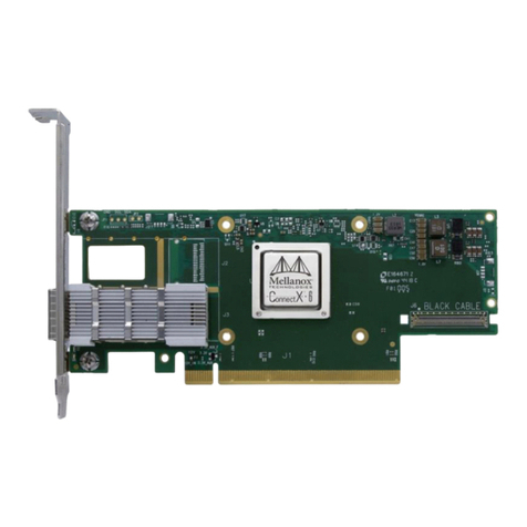
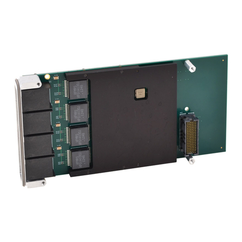
Acromag XMC630 Series User manual

-~
ARTISAN
®
~I
TECHNOLOGY
GROUP
Your definitive source
for
quality
pre-owned
equipment.
Artisan Technology
Group
Full-service,
independent
repair
center
with
experienced
engineers
and
technicians
on staff.
We
buy
your
excess,
underutilized,
and
idle
equipment
along
with
credit
for
buybacks
and
trade-ins
.
Custom
engineering
so
your
equipment
works
exactly as
you
specify.
•
Critical
and
expedited
services
•
Leasing
/
Rentals/
Demos
• In
stock/
Ready-to-ship
•
!TAR-certified
secure
asset
solutions
Expert
team
ITrust
guarantee
I
100%
satisfaction
All
tr
ademarks,
br
a
nd
names, a
nd
br
a
nd
s a
pp
earing here
in
are
th
e property of
th
e
ir
r
es
pecti
ve
ow
ner
s.
Find the Acromag XMC631-42-20 at our website: Click HERE

XMC630 Series Ethernet Network Interface Cards
USER’S MANUAL
ACROMAG INCORPORATED
30765 South Wixom Road
Wixom, MI 48393-2417 U.S.A.
Tel: (248) 295-0310
Copyright 2019, Acromag, Inc., Printed in the USA.
Data and specifications are subject to change without notice.
8501125A

XMC630 SERIES
USER’S MANUAL
Acromag, Inc. Tel: 248-295-0310 - 1 -
http://www.acromag.com
- 1 -
www.acromag.com
Table of Contents
1.0 RELATED PUBLICATIONS ................................................................................3
2.0 GENERAL INFORMATION .................................................................................4
2.1 Intended Audience ............................................................................................... 4
2.2 Preface................................................................................................................. 4
2.2.1 Trademark, Trade Name and Copyright Information ......................................................... 4
2.2.2 Class A Product Warning.................................................................................................... 4
2.2.3 Environmental Protection Statement ................................................................................ 4
2.3 Product Overview................................................................................................. 5
2.4 Ordering Information............................................................................................ 5
2.5 Key Features......................................................................................................... 6
2.6 Software Support ................................................................................................. 7
Windows................................................................................................................................. 7
Linux........................................................................................................................................ 7
2.7 Block Diagrams..................................................................................................... 8
Figure 2.7.1: XMC631 Block Diagram.......................................................................................... 8
Figure 2.7.2: XMC632 Block Diagram.......................................................................................... 8
3.0 PREPARATION FOR USE...................................................................................9
3.1 Unpacking and Inspecting ..................................................................................... 9
3.2 Installation Considerations ................................................................................. 10
3.3 Board Configuration ........................................................................................... 10
4.0 HARDWARE INFORMATION......................................................................... 11
4.1 Connector Information ....................................................................................... 11
4.1.1 P15 Primary XMC Connector............................................................................................ 11
4.1.2 P16 Secondary XMC Connector (XMC632 Only) ............................................................... 12
4.1.3 SFP+ Connectors (XMC631 Only)...................................................................................... 13

XMC630 SERIES
USER’S MANUAL
Acromag, Inc. Tel: 248-295-0310 - 2 -
http://www.acromag.com
- 2 -
www.acromag.com
5.0 SERVICE AND REPAIR .................................................................................... 14
5.1 Service and Repair Assistance ............................................................................. 14
5.2 Preliminary Service Procedure ............................................................................ 14
5.3 Where to Get Help.............................................................................................. 14
6.0 SPECIFICATIONS .............................................................................................. 15
6.1 Physical .............................................................................................................. 15
6.2 Power Requirements .......................................................................................... 15
6.3 Environmental Considerations ............................................................................ 16
6.3.1 Operating Temperature ................................................................................................... 16
6.3.2 Relative Humidity ............................................................................................................ 16
6.3.3 Vibration and Shock Standards........................................................................................ 16
6.3.4 EMC Directives................................................................................................................. 17
6.4 Reliability Prediction........................................................................................... 17
7.0 CERTIFICATE OF VOLATILITY..................................................................... 18
8.0 REVISION HISTORY......................................................................................... 19

XMC630 SERIES
USER’S MANUAL
Acromag, Inc. Tel: 248-295-0310 - 3 -
http://www.acromag.com
- 3 -
www.acromag.com
IMPORTANT SAFETY CONSIDERATIONS
It is very important for the user to consider the possible adverse effects of power, wiring, component, sensor, or
software failures in designing any type of control or monitoring system. This is especially important where
economic property loss or human life is involved. It is important that the user employ satisfactory overall
system design. It is agreed between the Buyer and Acromag, that this is the Buyer's responsibility.
1.0 RELATED PUBLICATIONS
The following specifications provide necessary information for in depth understanding of this product
and its use in a system architecture.
ANSI/VITA 42.0 –XMC Base Specification
ANSI/VITA 42.3 –XMC PCI Express Protocol Layer Standard
ANSI/VITA 42.6 –XMC 10 Gigabit Ethernet 4-Lane Protocol Layer Standard
IEEE 802.3 –2008 IEEE Standard for Ethernet
IEEE 802.3ae –2002 IEEE Amendment for 10 Gb/s Ethernet
SFF-8431 Enhanced Small Form Factor Pluggable Module SFP+

XMC630 SERIES
USER’S MANUAL
Acromag, Inc. Tel: 248-295-0310 - 4 -
http://www.acromag.com
- 4 -
www.acromag.com
2.0 GENERAL INFORMATION
2.1 Intended Audience
This users’ manual was written for technically qualified personnel who will
be working with networking devices using this XMC module. It is not
intended for a general, non-technical audience that is unfamiliar with XMC
modules and their application.
2.2 Preface
The information contained in this manual is subject to change without
notice, and Acromag, Inc. (Acromag) does not guarantee its accuracy.
Acromag makes no warranty of any kind with regards to this material,
including, but not limited to, the implied warranties of merchantability and
fitness for a particular purpose. Further, Acromag assumes no responsibility
for any errors that may appear in this manual and makes no commitment to
update, or keep current, the information contained in this manual. No part
of this manual may be copied or reproduced in any form, without the prior
written consent of Acromag,
2.2.1 Trademark, Trade Name and Copyright Information
© 2019 by Acromag Incorporated.
All rights reserved. Acromag and Xembedded are registered trademarks of
Acromag Incorporated. All other trademarks, registered trademarks, trade
names, and service marks are the property of their respective owners.
2.2.2 Class A Product Warning
This is a Class A product. In a domestic environment this product may cause
radio interference, in which case the user may find it necessary to take
adequate corrective measures.
2.2.3 Environmental Protection Statement
This product has been manufactured to satisfy environmental protection
requirements where possible. Many components used (structural parts,
circuit boards, connectors, etc.) are capable of being recycled. Final
disposition of this product after its service life must be conducted in
accordance with applicable country, state, or local laws or regulations.

XMC630 SERIES
USER’S MANUAL
Acromag, Inc. Tel: 248-295-0310 - 5 -
http://www.acromag.com
- 5 -
www.acromag.com
2.3 Product Overview
The XMC630 series modules are XMC modules that use the Intel XL710
Ethernet Controller to provide up to four 10-Gigabit Ethernet interfaces.
These modules interface with the PCIe bus via eight high-speed serial lanes
on the XMC P15 connector. The aggregate data rate of the four Ethernet
ports is limited by the PCIe host interface. A PCIe Gen3 x8 connection is
necessary to achieve full 4 x 10G bandwidth.
The XMC631 provides four 10GbE interfaces via SFP+ connectors available
on the front panel. The XMC632 provides two 10GbE XAUI interfaces
available as Rear I/O via the P16 connector.
2.4 Ordering Information
The following table lists the orderable models and their corresponding
operating temperature range. Each model is available with the standard
VITA 42 (XMC1.0) connectors or the high-speed VITA 61 (XMC2.0)
connectors.
MODELS
Description
OPERATING
TEMPERATURE RANGE
XMC631-42-20
4-Port SFP+ 10GbE NIC XMC
VITA 42 Style Connectors
0C to +70C1,2
XMC631-42-30
4-Port SFP+ 10GbE NIC XMC
VITA 42 Style Connectors
-40C to +85C1,2
XMC631-61-20
4-Port SFP+ 10GbE NIC XMC
VITA 61 Style Connectors
0C to +70C1,2
XMC631-61-30
4-Port SFP+ 10GbE NIC XMC
VITA 61 Style Connectors
-40C to +85C1,2
XMC632-42-50
2-Port XAUI 10GbE NIC XMC
VITA 42 Style Connectors
-40C to +85C
XMC632-61-50
2-Port XAUI 10GbE NIC XMC
VITA 61 Style Connectors
-40C to +85C
1. For applications requiring elevated operating temperatures, a minimum
airflow of 200LFM is recommended.
2. The temperature rating does not apply to the SFP transceiver modules.
Please consult the manufacturer’s documentation of the SFP module to
determine its operating temperature range.

XMC630 SERIES
USER’S MANUAL
Acromag, Inc. Tel: 248-295-0310 - 6 -
http://www.acromag.com
- 6 -
www.acromag.com
2.5 Key Features
PCIe Bus –The PCI Express Gen 3 interface operates at a bus speed of 8
Gbps per lane per direction. The XMC630 modules utilize a x8 PCIe
interface.
SFP+ Connectivity –Supports SFP connections for 10GBASE-SR, 10GBASE-LR,
10GBASE-T, and 10GSFP+Cu Direct Attach Copper physical media.
IEEE 1588 and 802.1AS Precision Timing –Time-stamping and
synchronization of time sensitive applications. Distribute common time to
connected devices.
IEEE 802.3az Energy Efficient Ethernet (EEE) –Power consumption is
reduced by approximately 50% during idle state.
Intel Ethernet Flow Director –Advanced traffic steering capability that
increases the number of transactions per second and reduces latency.
VMDq for Emulated Path –Virtual Machine Device Queues enable a
hypervisor to represent a single network port as multiple network ports that
can be assigned to individual VMs.
Dynamic Load Balancing –Increases performance by efficiently balancing
loads across CPU cores when used with Receive-Side Scaling from Microsoft
or scalable I/O in Linux.
Flexible Port Partitioning (PCI-SIG SR-IOV) –Up to 128 Virtual Functions
(VFs) appear as Ethernet Controllers in Linux OSes that can be assigned to
VMs, Kernel processes, or teamed using Linux Bonding Drivers.
Tx/Rx IP, TCP/UDP/SCTP, IPv4/IPv6 Checksum Offloads –Enables lower
processor usage. Checksum and segmentation capability extended to new
standard packet type.
Jumbo Frame Packet Support –Improves system performance related to
handling of network data on multiprocessor systems.

XMC630 SERIES
USER’S MANUAL
Acromag, Inc. Tel: 248-295-0310 - 7 -
http://www.acromag.com
- 7 -
www.acromag.com
2.6 Software Support
The XMC630 series products require support drivers specific to your
operating system. Supported operating systems include: Linux, Windows.
Windows
Acromag does not provide a custom Windows driver for these products. The
Windows driver for the Intel XL710 Ethernet Controller is available at
www.intel.com.
Linux
Acromag does not provide a custom Linux driver for these products. The
Linux driver for the Intel XL710 Ethernet Controller is available at
www.intel.com.

XMC630 SERIES
USER’S MANUAL
Acromag, Inc. Tel: 248-295-0310 - 8 -
http://www.acromag.com
- 8 -
www.acromag.com
2.7 Block Diagrams
Figure 2.7.1: XMC631 Block
Diagram
Figure 2.7.2: XMC632 Block
Diagram

XMC630 SERIES
USER’S MANUAL
Acromag, Inc. Tel: 248-295-0310 - 9 -
http://www.acromag.com
- 9 -
www.acromag.com
3.0 PREPARATION FOR USE
IMPORTANT PERSONAL AND PRODUCT SAFETY CONSIDERATIONS
It is very important for the user to consider the possible safety implications
of power, wiring, component, sensor, or software failures in designing any
type of control or monitoring system. This is especially important where
personal injury or the loss of economic property or human life is possible. It
is important that the user employ satisfactory overall system design. It is
understood and agreed by the Buyer and Acromag that this is the Buyer's
responsibility.
WARNING: This board utilizes static sensitive components and should only
be handled at a static-safe workstation. This product is an electrostatic
sensitive device and is packaged accordingly. Do not open or handle this
product except at an electrostatic-free workstation. Additionally, do not
ship or store this product near strong electrostatic, electromagnetic,
magnetic, or radioactive fields unless the device is contained within its
original manufacturer’s packaging. Be aware that failure to comply with
these guidelines will void the Acromag Limited Warranty.
3.1 Unpacking and Inspecting
Upon receipt of this product, inspect the shipping carton for evidence of
mishandling during transit. If the shipping carton is badly damaged or water
stained, request that the carrier's agent be present when the carton is
opened. If the carrier's agent is absent when the carton is opened and the
contents of the carton are damaged, keep the carton and packing material
for the agent's inspection.
For repairs to a product damaged in shipment, refer to the Acromag Service
Policy to obtain return instructions. It is suggested that salvageable shipping
cartons and packing material be saved for future use in the event the
product must be shipped.
This board is physically protected with packing material and electrically
protected with an anti-static bag during shipment. However, it is
recommended that the board be visually inspected for evidence of
mishandling prior to applying power.
The board utilizes static-sensitive components and should only be handled at
a static-safe workstation.

XMC630 SERIES
USER’S MANUAL
Acromag, Inc. Tel: 248-295-0310 - 10 -
http://www.acromag.com
- 10 -
www.acromag.com
3.2 Installation Considerations
IMPORTANT: Adequate air
circulation must be provided to
prevent a temperature rise
above the maximum operating
temperature.
Refer to the specifications for loading and power requirements. Be sure that
the system power supplies can accommodate the power requirements of
the carrier board, plus the installed XMC modules, within the voltage
tolerances specified.
The dense packing of the XMC module to the carrier/CPU board restricts air
flow within the card cage and is cause for concern. Adequate air circulation
must be provided to prevent a temperature rise above the maximum
operating temperature and to prolong the life of the electronics. If the
installation is in an industrial environment and the board is exposed to
environmental air, careful consideration should be given to air-filtering.
In a conduction cooled assembly, adequate thermal conduction must be
provided to prevent a temperature rise above the maximum operating
temperature.
3.3 Board Configuration
Power should be removed from the board when installing XMC modules,
cables, termination panels, and field wiring.

XMC630 SERIES
USER’S MANUAL
Acromag, Inc. Tel: 248-295-0310 - 11 -
http://www.acromag.com
- 11 -
www.acromag.com
4.0 HARDWARE INFORMATION
4.1 Connector Information
4.1.1 P15 Primary XMC Connector
The P15 XMC connector is wired per the VITA 42.0 standard. The P15
connector provides eight lanes of PCI Express to the Intel Ethernet Controller.
The PCIe interface is connected per the VITA 42.3 standard.
Table 4.1.1: Primary XMC
Connector P15
Pin
A
B
C
D
E
F
1
PET00+
PET00-
+3.3V
PET01+
PET01-
N.C.
2
GND
GND
TRST#
GND
GND
MRSTI#
3
PET02+
PET02-
+3.3V
PET03+
PET03-
N.C.
4
GND
GND
TCK
GND
GND
MRSTO#
5
PET04+
PET04-
+3.3V
PET05+
PET05-
N.C.
6
GND
GND
TMS
GND
GND
N.C.
7
PET06+
PET06-
+3.3V
PET07+
PET07-
N.C.
8
GND
GND
TDI
GND
GND
N.C.
9
N.C.
N.C.
N.C.
N.C.
N.C.
N.C.
10
GND
GND
TDO
GND
GND
GA0
11
PER00+
PER00-
MBIST#
PER01+
PER01-
N.C.
12
GND
GND
GA1
GND
GND
MPRSNT#
13
PER02+
PER02-
+3.3AUX
PER03+
PER03-
N.C.
14
GND
GND
GA2
GND
GND
MSDA
15
PER04+
PER04-
N.C.
PER05+
PER05-
N.C.
16
GND
GND
MVMRO
GND
GND
MSCL
17
PER06+
PER06-
N.C.
PER07+
PER07-
N.C.
18
GND
GND
N.C.
GND
GND
N.C.
19
REFCLK0_P
REFCLK0_N
N.C.
WAKE#
ROOT#
N.C.

XMC630 SERIES
USER’S MANUAL
Acromag, Inc. Tel: 248-295-0310 - 12 -
http://www.acromag.com
- 12 -
www.acromag.com
4.1.2 P16 Secondary XMC Connector (XMC632 Only)
The P16 connector is used to provide Rear network I/O support and thus will
only be populated on the XMC632 conduction-cooled model. The P16
secondary XMC connector connects the two 10GbE XAUI interfaces as shown
in Table 4.1.2. The XAUI interfaces are connected per the VITA 42.6 standard.
Table 4.1.2: Secondary XMC
Connector P16
Pin
A
B
C
D
E
F
1
X0_TX0_P
X0_TX0_N
NC
X0_TX1_P
X0_TX1_N
NC
2
GND
GND
NC
GND
GND
NC
3
X0_TX2_P
X0_TX2_N
NC
X0_TX3_P
X0_TX3_N
NC
4
GND
GND
NC
GND
GND
NC
5
X1_TX0_P
X1_TX0_N
NC
X1_TX1_P
X1_TX1_N
NC
6
GND
GND
NC
GND
GND
NC
7
X1_TX2_P
X1_TX2_N
NC
X1_TX3_P
X1_TX3_N
NC
8
GND
GND
NC
GND
GND
NC
9
NC
NC
NC
NC
NC
NC
10
GND
GND
NC
GND
GND
NC
11
X0_RX0_P
X0_RX0_N
NC
X0_RX1_P
X0_RX1_N
NC
12
GND
GND
NC
GND
GND
NC
13
X0_RX2_P
X0_RX2_N
NC
X0_RX3_P
X0_RX3_N
NC
14
GND
GND
NC
GND
GND
NC
15
X1_RX0_P
X1_RX0_N
NC
X1_RX1_P
X1_RX1_N
NC
16
GND
GND
NC
GND
GND
NC
17
X1_RX2_P
X1_RX2_N
NC
X1_RX3_P
X1_RX3_N
NC
18
GND
GND
NC
GND
GND
NC
19
NC
NC
NC
NC
NC
NC

XMC630 SERIES
USER’S MANUAL
Acromag, Inc. Tel: 248-295-0310 - 13 -
http://www.acromag.com
- 13 -
www.acromag.com
4.1.3 SFP+ Connectors (XMC631 Only)
On the XMC631 model, the four 10-Gigabit Ethernet interfaces are available via
standard SFP+ connectors. The XMC631 is fully compliant with the SFF-8431
Specifications for Enhanced Small Form Factor Pluggable Module SFP+. All SFF-
8431 compliant SFP+ modules are supported.
Table 4.1.3: SFP+
Connectors P1 –P4
11
VEER (GND)
VEER (GND)
10
12
RD-
RS1
9
13
RD+
RX_LOS
8
14
VEER (GND)
RS0
7
15
VCCR (+3.3V)
MOD_ABS
6
16
VCCT (+3.3V)
SCL
5
17
VEET (GND)
SDA
4
18
TD+
TX_DISABLE
3
19
TD-
TX_FAULT
2
20
VEET (GND)
VEET (GND)
1

XMC630 SERIES
USER’S MANUAL
Acromag, Inc. Tel: 248-295-0310 - 14 -
http://www.acromag.com
- 14 -
www.acromag.com
5.0 SERVICE AND REPAIR
5.1 Service and Repair Assistance
Surface-Mounted Technology (SMT) are generally difficult to repair. It is
highly recommended that a non-functioning board be returned to Acromag
for repair. The board can be damaged unless special SMT repair and service
tools are used. Further, Acromag has automated test equipment that
thoroughly checks the performance of each board.
Please refer to Acromag's Service Policy Bulletin or contact Acromag for
complete details on how to obtain parts and repair.
5.2 Preliminary Service Procedure
CAUTION: POWER MUST BE TURNED OFF BEFORE SERVICING BOARDS
Before beginning repair, be sure that all the procedures in the "Preparation
for Use" section have been followed. Also, refer to the documentation of
your carrier board to verify that it is correctly configured. Replacement of
the board with one that is known to work correctly is a good technique for
isolating a faulty part.
5.3 Where to Get Help
If the problem persists, the next step should be to visit the Acromag
worldwide web site at http://www.acromag.com. Our web site contains
the most up-to-date product and software information.
Go to the “Support” tab to access:
•Application Notes
•Frequently Asked Questions (FAQ’s)
•Product Knowledge Base
•Tutorials
•Software Updates/Drivers
Acromag’s application engineers can also be contacted directly for
technical assistance via email, telephone, or FAX through the contact
information listed below. Note that an email question can also be
submitted from within the Knowledge Base or directly from the “Contact
Us” tab. When needed, complete repair services are also available.
•Email: solutions@acromag.com
•Phone: 248-295-0310

XMC630 SERIES
USER’S MANUAL
Acromag, Inc. Tel: 248-295-0310 - 15 -
http://www.acromag.com
- 15 -
www.acromag.com
6.0 SPECIFICATIONS
6.1 Physical
Length: 149.0 mm (5.866 in.)
Width: 74.0 mm (2.913 in.)
Stacking Height: 10.0 mm (0.394 in.)
Weight XMC631: 104.2 g
Weight XMC632: 76.9 g
Unit weight does not include shipping materials.
6.2 Power Requirements
The XMC630 boards are powered by the 3.3V supply and the 5V/12V VPWR
supply present on the XMC P15 connectors. Both 5V and 12V are supported
as VPWR from the XMC carrier board. The optional auxiliary 3.3V supply on
the P15 connector can be used to power the IPMI FRU EEPROM device.
The following power consumption values were measured with 2 ports
utilized, 4 ports utilized, and with all ports idle or all ports active. Active
ports were measured while operating with continuous network traffic at link
speed at full duplex.
XMC631
3.3V (mA)
5V/12V (mA)
Total Power (W)
Typical Idle1
250
467/219
2.98
Typical Active2
250
565/260
3.49
Maximum3
400
1098/482
6.20
XMC632
3.3V (mA)
5V/12V (mA)
Total Power (W)
Typical Idle1
220
448/211
2.77
Typical Active2
220
498/232
3.04
Maximum3
330
1024/451
5.63
1. Idle is defined as typical conditions, Tj= 80°C, nominal voltages, and no
traffic.
2. Active is defined as typical conditions, Tj= 80°C, nominal voltages, and
continuous network traffic at link speed on all ports.
3. Maximum is defined as maximum conditions, max operating
temperature (Tj= 110°C), nominal voltages, and continuous network
traffic at link speed on all ports.

XMC630 SERIES
USER’S MANUAL
Acromag, Inc. Tel: 248-295-0310 - 16 -
http://www.acromag.com
- 16 -
www.acromag.com
6.3 Environmental Considerations
6.3.1 Operating Temperature
Table 6.3.1: Operating
Temperature
MODELS
DESCRIPTION
OPERATING
TEMPERATURE RANGE
XMC631-XX-20
4-Port SFP+ 10GbE NIC XMC
0C to +70C1,2
XMC631-XX-30
4-Port SFP+ 10GbE NIC XMC
-40C to +85C1,2
XMC632-XX-50
2-Port XAUI 10GbE NIC XMC
-40C to +85C3
1. For applications requiring elevated operating temperatures, a minimum
airflow of 200LFM is recommended.
2. The temperature rating does not apply to the SFP transceiver modules.
Please consult the manufacturer’s documentation of the SFP module to
determine its operating temperature range.
3. For conduction-cooled applications, adequate thermal conduction must
be provided to prevent a temperature rise above the maximum
operating temperature.
6.3.2 Relative Humidity
The range of acceptable relative humidity is 5% to 95% non-condensing.
6.3.3 Vibration and Shock Standards
The XMC630 series products are designed to comply with the following
Vibration and Shock standards.
Vibration, Random Operating: Designed to comply with VITA 47 Class V1.
Shall withstand vibration from 5 to 100Hz. with Power Spectral Density (PSD)
= 0.04g2/Hz, for 1 hour per axis. Testing shall be in accordance with MIL-
STD-810, Method 514, Procedure 1
Shock, Operating: Designed to comply with VITA 47 Class OS1, 20g, 11ms
half sine and terminal sawtooth shock pulses. 3 shock pulses in each
direction along 3 axes (36 shocks, total). Testing shall be in accordance with
MIL-STD-810, Method 516, Procedure 1.
Summarized below are the operating temperature range, airflow and other
environmental requirements and applicable standards for the XMC630
Series modules.

XMC630 SERIES
USER’S MANUAL
Acromag, Inc. Tel: 248-295-0310 - 17 -
http://www.acromag.com
- 17 -
www.acromag.com
6.3.4 EMC Directives
The XMC630 family is designed to comply with EMC Directive 2004/108/EC.
•Immunity per EN 61000-6-2:
Electrostatic Discharge Immunity (ESD), per IEC 61000-4-2.
Radiated Field Immunity (RFI), per IEC 61000-4-3.
Electrical Fast Transient Immunity (EFT), per IEC 61000-4-4.
Surge Immunity, per IEC 61000-4-5.
Conducted RF Immunity (CRFI), per IEC 61000-4-6.
•Emissions per EN 61000-6-4:
Enclosure Port, per CISPR 16.
Low Voltage AC Mains Port, per CISPR 16.
Note: This is a Class A product
6.4 Reliability Prediction
Table 6.4.1: XMC631 MTBF
Predictions
MTBF (Mean Time Between Failure): MTBF in hours using MIL-HDBK-217F,
FN2. Per MIL-HDBK-217, Ground Benign, Controlled, GBGC
Temperature
MTBF (Hours)
MTBF (Years)
Failure Rate (FIT1)
25°C
1,412,382
161.2
708.0
40°C
846,375
96.6
1,181.5
1FIT is Failures in 109hours.
Table 6.4.2: XMC632 MTBF
Predictions
MTBF (Mean Time Between Failure): MTBF in hours using MIL-HDBK-217F,
FN2. Per MIL-HDBK-217, Ground Benign, Controlled, GBGC
Temperature
MTBF (Hours)
MTBF (Years)
Failure Rate (FIT1)
25°C
1,485,286
169.6
673.3
40°C
894,775
102.1
1,117.6
1FIT is Failures in 109hours.

XMC630 SERIES
USER’S MANUAL
Acromag, Inc. Tel: 248-295-0310 - 18 -
http://www.acromag.com
- 18 -
www.acromag.com
7.0 Certificate of Volatility
Certificate of Volatility
Acromag Models:
XMC631-42-20
XMC631-42-30
XMC631-61-20
XMC631-61-30
XMC632-42-50
XMC632-61-50
Manufacturer:
Acromag, Inc.
30765 Wixom Rd
Wixom, MI 48393
Volatile Memory
Does this product contain Volatile memory (i.e. Memory of whose contents are lost when power is removed)?
□ Yes ■No
Type (SRAM, SDRAM,
etc.)
Size:
User Modifiable
□ Yes
□ No
Function:
Process to Sanitize:
Non-Volatile Memory
Does this product contain Non-Volatile memory (i.e. Memory of whose contents is retained when power is removed)?
■Yes □ No
Type (EEPROM, Flash,
etc.)
EEPROM
Size:
2 Kbit
User Modifiable
■Yes
□ No
Function:
FRU Records
Process to Sanitize:
Clear EEPROM by
erasing all bytes.
Type (EEPROM, Flash,
etc.)
Flash
Size:
128 Mbit
User Modifiable
□Yes
■No
Function:
XL710
Configuration Data
Process to Sanitize:
Clear Flash by
erasing all bytes.
Acromag Representative
Name:
Russ Nieves
Title:
Dir. of Sales and Marketing
Email:
solutions@acromag.com
Office Phone:
248-295-0310
Office Fax:
248-624-9234
This manual suits for next models
8
Table of contents
Other Acromag Computer Hardware manuals

Acromag
Acromag ACPS3320 User manual

Acromag
Acromag IOS-7200 User manual
Acromag
Acromag APCe8775 User manual

Acromag
Acromag APCe8675 User manual

Acromag
Acromag BusWorks XT Series User manual

Acromag
Acromag AVME9440 Series User manual
Acromag
Acromag APCe7012E-LF User manual
Acromag
Acromag XVME-6700 User manual

Acromag
Acromag XVPX-6300 User manual
Acromag
Acromag XMC610 Series User manual
