Acromag AVME9670A Series User manual

Series AVME9670A Industrial I/O Pack
VME64x Bus 6U Non-Intelligent Carrier Boards
USER’S MANUAL
ACROMAG INCORPORATED
30765 South Wixom Road
Wixom, MI 48393-2417 U.S.A.
Tel: (248) 295-0310
Email: solutions@acromag.com
Copyright 2020, Acromag, Inc., Printed in the USA.
Data and specifications are subject to change without notice.
8501170A

INDUSTRIAL I/O PACK SERIES
AVME9675A
VMEx64 bus 6U CARRIER BOARD
Acromag, Inc. Tel: 248-295-0310 - 1 -
http://www.acromag.com
- 1 -
https://ww.acromag.com
Table of Contents
1.0 GENERAL INFORMATION..........................................................................................5
1.1 Intended Audience .......................................................................................................5
1.2 Preface.........................................................................................................................5
1.2.1 Trademark, Trade Name and Copyright Information .................................................................. 5
1.2.2 Class A Product Warning............................................................................................................. 5
1.2.3 Environmental Protection Statement ......................................................................................... 5
1.3 Carrier Information.......................................................................................................5
1.3.1 Ordering Information ................................................................................................................. 6
1.3.2Key Features............................................................................................................................... 6
1.3.3 Key Features VME64x bus Interface............................................................................................ 7
1.4 Signal Interface Products ..............................................................................................8
1.5 Software Support .........................................................................................................9
Windows............................................................................................................................................ 9
VxWorks............................................................................................................................................ 9
Linux.................................................................................................................................................. 9
2.0 PREPARATION FOR USE........................................................................................... 10
2.1 Unpacking and Inspecting...........................................................................................10
2.2 Card Cage Considerations ...........................................................................................11
2.3 Board Configuration ...................................................................................................11
2.4 VME64x Bus Interface Configuration...........................................................................11
2.5 Address Decode Jumper Configuration .......................................................................11
Table 2.1: Address Decode Jumper Selections (J1 Pins)......................................................12
2.6 VMEbus Address Modifiers.........................................................................................12
2.7 Interrupt Configuration ..............................................................................................13
2.8 Carrier Field I/O Connectors (IP modules A through D)................................................13
2.9 IP Field I/O Connectors (IP modules A through D) .......................................................13

INDUSTRIAL I/O PACK SERIES
AVME9675A
VME64x bus 6U CARRIER BOARD
Acromag, Inc. Tel: 248-295-0310 - 2 -
http://www.acromag.com
- 2 -
https://www.acromag.com
2.10 IP Logic Interface Connectors (IP modules A through D) ............................................14
Table 2.2 Standard IP Logic Interface Connections (P4,6,8,10).............................................14
2.11 VME64x bus Connections..........................................................................................15
Table 2.3 VMEbus P1 CONNECTIONS..................................................................................15
TABLE 2.4: VME64x bus P2 CONNECTIONS.........................................................................17
2.12 POWER UP TIMING AND LOADING............................................................................19
2.13 DATA TRANSFER TIMING ..........................................................................................19
2.14 FIELD GROUNDING CONSIDERATIONS.......................................................................20
3.0 PROGRAMMING INFORMATION........................................................................... 21
Table 3.1A AVME9670A 6U Carrier Bd Short I/O Memory Map...........................................21
Table 3.1B: AVME9670A Carrier Board Registers ...............................................................23
3.1 Identification ROM (Read Only, 32 Odd Byte Addresses).............................................25
Table 3.2: Generic IP Module ID Space Identification (ID) ROM...........................................26
3.2 Carrier Board Status Register (Read/Write, Base + C1H)..............................................26
3.3 Interrupt Level Register (Read/Write, Base + C3H) ......................................................28
3.4 IP Error Register (Read, Base + C5H)............................................................................29
3.5 IP Memory Enable Register (Read/Write, Base + C7H).................................................29
3.6 IP Memory Base Address & Size Register (Read/Write) ...............................................30
IP_A (Base + D1H), IP_B (Base + D3H), IP_C (Base + D5H), IP_D (Base + D7H),......................30
3.7 IP Interrupt Enable Register (Read, Base + E1H) ..........................................................31
3.8 IP Interrupt Pending Register (Read, Base + E3H) ........................................................31
3.9 IP Interrupt Clear Register (Write, Base + E5H)............................................................32
Firmware Revision Register (Read Only) - (BAR0 + 0x0000 0200) , Base + F1H .....................................32
XADC Status/Control Register (Read/Write) - Base + F9H ....................................................................33
XADC Address Register (Read/Write) - Base + FBH...............................................................................33
System Monitor Register Map..................................................................................................... 33

INDUSTRIAL I/O PACK SERIES
AVME9675A
VMEx64 bus 6U CARRIER BOARD
Acromag, Inc. Tel: 248-295-0310 - 3 -
http://www.acromag.com
- 3 -
https://ww.acromag.com
3.10 GENERAL PROGRAMMING CONSIDERATIONS ...........................................................34
3.11 Board Diagnostics.....................................................................................................34
3.12 GENERATING INTERRUPTS ........................................................................................34
3.13 Interrupt Configuration Example...............................................................................35
3.14 Sequence of Events for an Interrupt..........................................................................35
4.0 THEORY OF OPERATION......................................................................................... 37
4.1 CARRIER BOARD OVERVIEW.........................................................................................37
4.2 VME64x bus Interface.................................................................................................37
4.3 Carrier Board Registers...............................................................................................38
4.4 IP Logic Interface ........................................................................................................39
4.5 Carrier Board Clock Circuitry.......................................................................................39
4.6 IP Read and Write Cycle Timing ..................................................................................40
4.7 VME64x Bus Interrupter .............................................................................................41
4.8 Power Failure Monitor................................................................................................42
4.9 Access LEDs and Pulse Stretcher Circuitry....................................................................42
4.10 Power Supply Filters .................................................................................................42
4.11 Power Supply Fuses ..................................................................................................42
5.0 SERVICE AND REPAIR............................................................................................... 43
5.1 Service and Repair Assistance.....................................................................................43
5.2 Preliminary Service Procedure ....................................................................................43
5.3 Where to Get Help......................................................................................................43
6.0 SPECIFICATIONS......................................................................................................... 44
6.1 Physical......................................................................................................................44

INDUSTRIAL I/O PACK SERIES
AVME9675A
VME64x bus 6U CARRIER BOARD
Acromag, Inc. Tel: 248-295-0310 - 4 -
http://www.acromag.com
- 4 -
https://www.acromag.com
6.2 Power Requirements..................................................................................................44
6.3 Environmental Considerations....................................................................................45
6.3.1 Operating Temperature.............................................................................................................45
6.3.2. Relative Humidity.....................................................................................................................45
6.3.3Storage Temperature.................................................................................................................45
EMC Directives.....................................................................................................................................46
FCC US/Canada ....................................................................................................................................46
6.4 Reliability Prediction ....................................................................................................46
Table 6.4.1 AVME9670A.......................................................................................................................46
6.5 INDUSTRIAL I/O PACK COMPLIANCE ...........................................................................46
6.6 VME64x bus COMPLIANCE..........................................................................................47
APPENDIX.............................................................................................................................. 48
CABLE: MODEL 5028-187 (SCSI-2 to Flat Ribbon, Shielded).................................................48
Termination Panel Model 5025-552 ...................................................................................48
VME64x TRANSITION MODULE: MODEL TRANS-200...........................................................49
DRAWINGS ............................................................................................................................ 50
4501-755 AVME9670A JUMPER & IP LOCATIONS................................................................50
4501-756 MECHANICAL ASSEMBLY DRAWING....................................................................51
4501-757 AVME9670A BLOCK DIAGRAM............................................................................52
4501-758 CABLE, SCSI-2 to Flat Ribbon (Shielded) 5028-187................................................52
4501-464 TERMINATION PANEL 5025-552 ..........................................................................53
4501-760 VME64x Transition Mod., TRANS-200..................................................................55
CERTIFICATE OF VOLATILITY ........................................................................................ 56
REVISION HISTORY ............................................................................................................ 57

INDUSTRIAL I/O PACK SERIES
AVME9675A
VMEx64 bus 6U CARRIER BOARD
Acromag, Inc. Tel: 248-295-0310 - 5 -
http://www.acromag.com
- 5 -
https://ww.acromag.com
1.0 GENERAL INFORMATION
1.1 Intended Audience
This users’ manual was written for technically qualified personnel who will
be working with I/O devices using the Industrial Pack module. It is not
intended for a general, non-technical audience that is unfamiliar with I/O
devices and their application.
1.2 Preface
The information contained in this manual is subject to change without
notice, and Acromag, Inc. (Acromag) does not guarantee its accuracy.
Acromag makes no warranty of any kind with regard to this material,
including, but not limited to, the implied warranties of merchantability and
fitness for a particular purpose. Further, Acromag assumes no responsibility
for any errors that may appear in this manual and makes no commitment to
update, or keep current, the information contained in this manual. No part
of this manual may be copied or reproduced in any form, without the prior
written consent of Acromag,
1.2.1 Trademark, Trade Name and Copyright Information
© 2017 by Acromag Incorporated.
All rights reserved. Acromag and Xembedded are registered trademarks of
Acromag Incorporated. All other trademarks, registered trademarks, trade
names, and service marks are the property of their respective owners.
1.2.2 Class A Product Warning
This is a Class A product. In a domestic environment this product may cause
radio interference, in which case the user may find it necessary to take
adequate corrective measures.
1.2.3 Environmental Protection Statement
This product has been manufactured to satisfy environmental protection
requirements where possible. Many components used (structural parts,
circuit boards, connectors, etc.) are capable of being recycled. Final
disposition of this product after its service life must be conducted in
accordance with applicable country, state, or local laws or regulations.
1.3 Carrier Information
The AVME9670A VME64x bus card is a carrier for the Industrial I/O Pack (IP)
mezzanine board field I/O modules. The Industrial I/O Packs field I/O exits
the carrier via the rear panel per the VME64 Extensions (ANSI/VITA 1.1-
1997). The carrier boards facilitate a modular approach to system assembly,
since each carrier can be populated with any combination of analog

INDUSTRIAL I/O PACK SERIES
AVME9675A
VME64x bus 6U CARRIER BOARD
Acromag, Inc. Tel: 248-295-0310 - 6 -
http://www.acromag.com
- 6 -
https://www.acromag.com
input/output and digital input/output IP modules. Thus, the user can create
a board which is customized to the application which saves money and
space - a single carrier board populated with IP modules may replace several
dedicated function VMEbus boards. The AVME9670A non-intelligent carrier
boards provide impressive functionality at low cost.
1.3.1 Ordering Information
Model is available in one standard VME64x bus 6U size, with support for up
to four IP modules.
Model Number
Operating Temperature Range
Supported IP
Slots
AVME9670A-2E-LF
-40 to +85 °C
2 (A,B)
AVME9670A-4E-LF
-40 to +85 °C
4 (A,B,C,D)
1.3.2 Key Features
•Supports Four IP Modules - Provides an electrical and mechanical
interface for up to four industry standard IP modules. IP Modules
are available from Acromag and other vendors in a wide variety of
Input/Output configurations to meet the needs of varied
applications.
•Provides Full IP Data Access - Supports accesses to IP input/output,
memory, identification data, and interrupt spaces.
•Full IP Register Access - Makes maximum use of logically organized
programmable registers on the carrier boards to provide for easy
configuration and control of IP modules. The only hardware jumper
settings required on the carrier boards set the base address of the
card in the VME64x bus short I/O space.
•LED Indicators Simplify Debugging–Front panel LED's are dedicated
to each IP module to give a visual indication of successful IP
accesses.
•Optional Screw Termination Panel –Model supports field
connection via screw terminals using the optional DIN rail mount
termination panel (Model 5028-182).
•LED Indicators Simplify Debugging - Front panel LED's are dedicated
to each IP module to give a visual indication of successful IP
accesses.
•Rear Backplane Connectors Access I/O - Rear backplane connectors
P0 and P2 access to field I/O signals mapped per the VME64x IP I/O
(ANSI/VITA 4.1-1996) specification. A transition module (Acromag
Model TRANS-200) routes the field I/O signals from P0 and P2 to
the rear of the cage system with separate SCSI-2 connectors for
each IP module. All SCSI-2 connectors can be connected with a
standard SCSI-2 cable from the transition module without

INDUSTRIAL I/O PACK SERIES
AVME9675A
VMEx64 bus 6U CARRIER BOARD
Acromag, Inc. Tel: 248-295-0310 - 7 -
http://www.acromag.com
- 7 -
https://ww.acromag.com
interference from boards in adjacent slots. Spring latch hardware
on the transition module provide for excellent connection integrity
and easy cable removal.
•Memory Space Access Support - IP memory space accesses are
supported and software configurable from 1Mbyte to 8Mbytes in
the VME64x bus standard address space.
•Supports Two Interrupt Channels per IP - Up to two interrupt
requests are supported for each IP. The VME64x bus interrupt level
is software programmable. Additional registers are associated with
each interrupt request for control and status monitoring.
•Interrupt Priority Control - Interrupts use a priority shifting scheme
based on the last interrupt serviced. This prevents the continuous
interrupts of one IP module interrupt request from blocking the
interrupts of other IP modules.
•Supervisory Circuit for Reset Generation - A microprocessor
supervisor circuit provides power-on, power-off, and low power
detection reset signals to the IP modules per the IP specification.
•Individually Filtered Power - Filtered +5V, +12V, and -12V DC power
is provided to the IP modules via passive filters present on each
supply line serving each IP. This provides optimum filtering and
isolation between the IP modules and the carrier board and allows
analog signals to be accurately measured or reproduced on IP
modules without signal degradation from the carrier board logic
signal noise.
•ESD Strip - The AVME9670A board has been designed to provide
electrostatic discharge (ESD) capability by using an ESD strip on the
board per ANSI/VITA 1.1-1997 and IEEE1101.10.
•Injector/Ejector Handles - The AVME9670A uses modern
injector/ejector handles, which push the board into the rack during
installation and pull the board out of the rack for removal or
replacement. These handles are needed to give you leverage to
install and remove the board.
1.3.3 Key Features VME64x bus Interface
•Slave Module-
Carrier Register Short I/O Access A16, D16/D08(O)
IP Module ID Space A16, D16/D08(O)
IP Module I/O Space A16, D16/D08(EO)
IP Module Memory Space A24, D16/D08(EO)
•Supports Short I/O Address Modifiers - Supports short I/O (A16)
address modifiers 29H, 2DH (H = Hex). Short I/O space is used for all
carrier registers and IP module I/O and ID spaces. The carrier board

INDUSTRIAL I/O PACK SERIES
AVME9675A
VME64x bus 6U CARRIER BOARD
Acromag, Inc. Tel: 248-295-0310 - 8 -
http://www.acromag.com
- 8 -
https://www.acromag.com
base address is set by hardware jumpers and decoded on 1K byte
boundaries.
•Supports Standard I/O Address Modifiers - Supports standard (A24)
address modifiers 39H, 3DH (H = Hex). Standard address space is
used when an IP supports memory space. The carrier board is
configured using programmable registers to set the IP starting
address and size (1Mbyte to 8Mbytes).
•Supports Read-Modify-Write Cycles - Carrier board supports
VME64x bus read-modify-write cycles.
•Interrupt Support - I(1-7) interrupter D16/D08 (O). Up to two
interrupt requests are supported for each IP module. The VME64x
bus interrupt level is software programmable. Carrier board
software programmable registers are utilized as interrupt request
control and status monitors. Interrupt release mechanism is Release
On Register Access (RORA) type.
1.4 Signal Interface Products
(See Appendix for more information on compatible products)
This IP carrier board will mate directly to all industry standard 8 MHz IP
modules. Acromag provides the following interface products (all
connections to field signals are made through the carrier board and
transition module which passes them to the individual IP modules):
Cables:
Model 5028-187 (SCSI-2 to Flat Ribbon Cable, Shielded): A round 50
conductor shielded cable with a male SCSI-2 connector at one end and a flat
female ribbon connector at the other end. The cable is used for connecting
AVME9670A with the TRANS-200, or other compatible carrier boards, to
Model 5025-552 termination panels.
Termination Panel:
Model 5025-552: DIN-rail mountable panel provides 50 screw terminals for
universal field I/O termination. Connects to Acromag AVME9670A with the
TRANS-200, or other compatible carrier boards, via SCSI-2 to Flat Ribbon
Cable, Shielded (Model 5028-187).
Transition Module:
Model TRANS-200: This module plugs into the rear backplane directly
behind the carrier board. The field I/O connections are made through the
backplane to P0 and P2 connectors of the carrier board and then routed to
four SCSI-2 connectors on the transition module (marked IP module slots “A
through D”) for rear exit from the card cage. It is available for use in
VME64x bus card cages which provide rear exit for I/O connections via

INDUSTRIAL I/O PACK SERIES
AVME9675A
VMEx64 bus 6U CARRIER BOARD
Acromag, Inc. Tel: 248-295-0310 - 9 -
http://www.acromag.com
- 9 -
https://ww.acromag.com
transition modules (transition modules can only be used in card cages
specifically designed for them). It is a double-height (6U), single-slot module
with front panel hardware adhering to the VME64x bus mechanical
dimensions and IEEE Standard (1101.11-1998), with a printed circuit board
depth of 80mm, which is a standard transition module depth. The transition
module connects to Acromag Termination Panel (Model 5025-552) using
SCSI-2 to Flat Ribbon Cable, Shielded (Model 5028-187) to the rear of the
card cage, and to AVME9670A boards within the card cage.
1.5Software Support
The Industry Pack series products require support drivers specific to your
operating system. Supported operating systems include: Linux, Windows,
and VxWorks
Windows
Acromag provides software products (sold separately) to facilitate the
development of Windowsapplications interfacing with Industry Pack
modules. This software (model IPSW-API-WIN) consists of low-level drivers
and Dynamic Link Libraries (DLLs) that are compatible with a number of
programming environments. The DLL functions provide a high-level
interface to boards eliminating the need to perform low-level reads/writes
of registers, and the writing of interrupt handlers.
VxWorks
Acromag provides a software product (sold separately) consisting of
VxWorkssoftware. This software (Model IPSW-API-VXW) is composed of
VxWorks(real time operating system) libraries for all Industry Pack
modules. The software is implemented as a library of “C” functions which
link with existing user code to make possible simple control of all Acromag
Industry Pack modules.
Linux
Acromag provides a software product consisting of Linuxsoftware. This
software (Model IPSW-API-LNX) is composed of Linuxlibraries for all
Industry Pack modules. The software is implemented as a library of “C”
functions which link with existing user code to make possible simple control
of all Acromag Industry Pack modules.
INDUSTRIAL I/O PACK SERIES
AVME9675A
VME64x bus 6U CARRIER BOARD
Acromag, Inc. Tel: 248-295-0310 - 10 -
http://www.acromag.com
- 10 -
https://www.acromag.com
2.0 PREPARATION FOR USE
IMPORTANT PERSONAL AND PRODUCT SAFETY CONSIDERATIONS
It is very important for the user to consider the possible safety implications
of power, wiring, component, sensor, or software failures in designing any
type of control or monitoring system. This is especially important where
personal injury or the loss of economic property or human life is possible. It
is important that the user employ satisfactory overall system design. It is
understood and agreed by the Buyer and Acromag that this is the Buyer's
responsibility.
WARNING: This board utilizes static sensitive components and should only
be handled at a static-safe workstation. This product is an electrostatic
sensitive device and is packaged accordingly. Do not open or handle this
product except at an electrostatic-free workstation. Additionally, do not
ship or store this product near strong electrostatic, electromagnetic,
magnetic, or radioactive fields unless the device is contained within its
original manufacturer’s packaging. Be aware that failure to comply with
these guidelines will void the Acromag Limited Warranty.
2.1 Unpacking and Inspecting
Upon receipt of this product, inspect the shipping carton for evidence of
mishandling during transit. If the shipping carton is badly damaged or water
stained, request that the carrier's agent be present when the carton is
opened. If the carrier's agent is absent when the carton is opened and the
contents of the carton are damaged, keep the carton and packing material
for the agent's inspection.
For repairs to a product damaged in shipment, refer to the Acromag Service
Policy to obtain return instructions. It is suggested that salvageable shipping
cartons and packing material be saved for future use in the event the
product must be shipped.
This board is physically protected with packing material and electrically
protected with an anti-static bag during shipment. However, it is
recommended that the board be visually inspected for evidence of
mishandling prior to applying power.
The board utilizes static-sensitive components and should only be handled at
a static-safe workstation.

INDUSTRIAL I/O PACK SERIES
AVME9675A
VMEx64 bus 6U CARRIER BOARD
Acromag, Inc. Tel: 248-295-0310 - 11 -
http://www.acromag.com
- 11 -
https://ww.acromag.com
2.2 Card Cage Considerations
IMPORTANT: Adequate air
circulation must be provided to
prevent a temperature rise
above the maximum operating
temperature.
Refer to the specifications for loading and power requirements. Be sure
that the system power supplies are able to accommodate the power
requirements of the carrier board, plus the installed IP modules, within the
voltage tolerances specified.
The dense packing of the IP modules to the carrier board restricts air flow
within the card cage and is cause for concern. Adequate air circulation
must be provided to prevent a temperature rise above the maximum
operating temperature and to prolong the life of the electronics. If the
installation is in an industrial environment and the board is exposed to
environmental air, careful consideration should be given to air-filtering.
2.3 Board Configuration
The carrier board may be configured for different applications. All possible
configuration settings will be discussed in the following Sections. The
jumper locations and IP module positions are shown in Drawing 4501-755.
Power should be removed from the board when installing IP modules,
cables, termination panels, and field wiring. Refer to Mechanical Assembly
Drawing 4501-756 and your IP module documentation for specific
configuration and assembly instructions.
2.4 VME64x Bus Interface Configuration
The carrier board is shipped from the factory configured as follows:
•Carrier board with VME64x bus Short I/O Base Address of 0000H.
Board will respond to both Address Modifiers 29H and 2DH.
Registers on the carrier board plus the I/O and ID spaces on any
installed IP modules will be accessible.
•Programmable software registers default to IP memory space
(VME64x bus standard address space) accesses disabled.
•Programmable software registers default to IP interrupt requests-
disabled and VME64x bus interrupt level-none.
2.5Address Decode Jumper Configuration
The carrier board interfaces with the VME64x bus as a 1K byte block of
address locations in the VME64x bus short I/O address space (refer to
Section 3 for memory map details). J1 decodes the six most significant
address lines A10 through A15 to provide segments of 1K address space.
INDUSTRIAL I/O PACK SERIES
AVME9675A
VME64x bus 6U CARRIER BOARD
Acromag, Inc. Tel: 248-295-0310 - 12 -
http://www.acromag.com
- 12 -
https://www.acromag.com
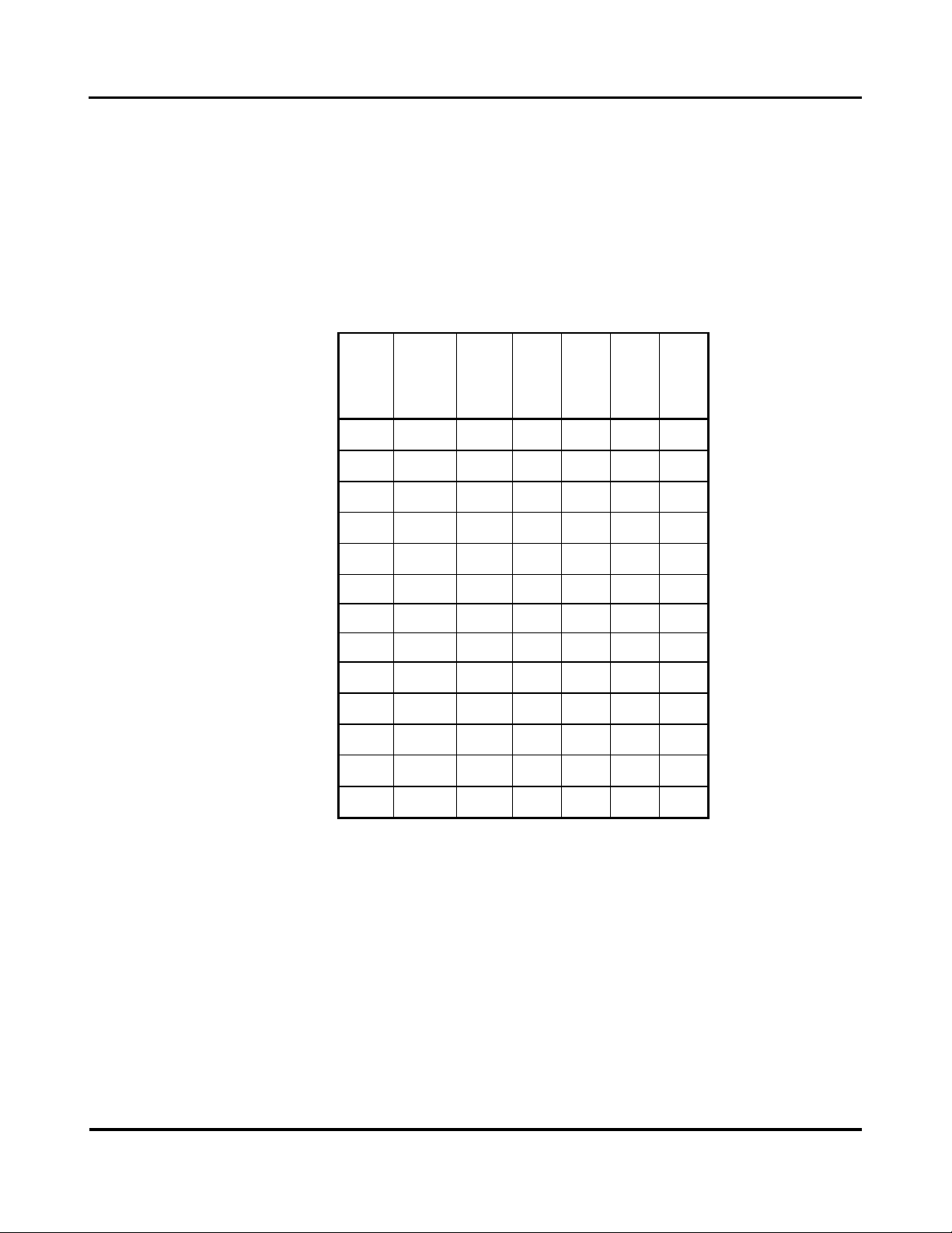
The configuration of the jumpers for different base address locations is
shown in Table 2.1. "IN" means that the pins are shorted together with a
shorting clip. "OUT" indicates that the clip has been removed.
Table 2.1: Address Decode Jumper Selections (J1 Pins)
Base
Addr*
(Hex)
A15
(11&12)
A14
(9&10)
A13
(7&8)
A12
(5&6)
A11
(3&4)
A10
(1&2)
0000
OUT
OUT
OUT
OUT
OUT
OUT
0400
OUT
OUT
OUT
OUT
OUT
IN
0800
OUT
OUT
OUT
OUT
IN
OUT
0C00
OUT
OUT
OUT
OUT
IN
IN
1000
OUT
OUT
OUT
IN
OUT
OUT
.
.
.
.
.
.
.
.
.
.
.
.
.
.
.
.
.
.
.
.
.
EC00
IN
IN
IN
OUT
IN
IN
F000
IN
IN
IN
IN
OUT
OUT
F400
IN
IN
IN
IN
OUT
IN
F800
IN
IN
IN
IN
IN
OUT
FC00
IN
IN
IN
IN
IN
IN
•Consult your host CPU manual for detailed information about
addressing the VME64x bus short I/O (A16, 16-bit) space. In many
cases, CPU's utilizing 24-bit addressing will start the 16-bit address at
FF0000 (Hex), and 32-bit CPU's at FFFF0000 (Hex).
2.6VMEbus Address Modifiers
No hardware jumper configuration is needed. The carrier board will
respond to both address modifiers 29H and 2DH in the VME64x bus short
I/O space. This means that both short supervisory and short non-privileged
accesses are supported.

INDUSTRIAL I/O PACK SERIES
AVME9675A
VMEx64 bus 6U CARRIER BOARD
Acromag, Inc. Tel: 248-295-0310 - 13 -
http://www.acromag.com
- 13 -
https://ww.acromag.com
The carrier board will respond to both address modifiers 39H and 3DH in the
VME64x bus standard address space, when standard address space accesses
to IP memory are enabled via programmable registers on the carrier board
(refer to Section 3 for programming details).
2.7 Interrupt Configuration
No hardware jumper configuration is required. All interrupt enabling,
status, and VME64x bus interrupt level selections are configured via
programmable registers on the carrier board (see Section 3 for
programming details). The carrier board passes interrupt requests from the
IP modules to the VME64x bus --It does not originate interrupt requests.
Refer to the IP modules for their specific configuration requirements.
2.8 Carrier Field I/O Connectors (IP modules A through D)
Field I/O connections are made through the rear via transition module
(TRANS-200) connectors A, B, C, and D for IP modules in positions A through
D, respectively. IP module assignment is marked on the transition module
for easy identification (see jumper & IP location drawing 4501-756 for
physical locations of the IP modules). SCSI-2 Round cable assemblies and
Acromag termination panels (or user defined terminations) can be quickly
mated to the transition module connectors. Pin assignments are defined by
the IP I/O Mapping to VME64x Standard (ANSI/VITA 4.1-1996).
Connectors A through D are 50-pin SCSI-2 right angle (female) connectors
(AMP). Connectors are high-density, and there is one connector for each IP
module marked with A, B, C, & D on the transition module panel. These
connectors include spring latch hardware and 30 microns of gold in the
mating area for excellent connection.
2.9IP Field I/O Connectors (IP modules A through D)
The field side connectors of IP modules A through D mate to connectors P7,
P8, P9, and P10, respectively, on the carrier board. IP location is silk-
screened on the board for easy identification. Field and logic side
connectors are keyed to avoid incorrect assembly.
P7, P8, P9, and P10 are 50-pin male plug header connectors. These AMP
173280-3 connectors mate to AMP 173279-3 connectors (or similar) on the
IP modules. This provides excellent connection integrity and utilizes gold
plating in the mating area. Threaded metric M2 screws and spacers
(supplied with Acromag IP modules) provide additional stability for harsh
environments (see Drawing 4501-756 for assembly details).

INDUSTRIAL I/O PACK SERIES
AVME9675A
VME64x bus 6U CARRIER BOARD
Acromag, Inc. Tel: 248-295-0310 - 14 -
http://www.acromag.com
- 14 -
https://www.acromag.com
Pin assignments for these connectors are made by the specific IP model
used and correspond identically to the pin numbers of the transition module
panel connectors.
2.10 IP Logic Interface Connectors (IP modules A through D)
The logic interface sides of IP modules A through D mate to connectors P11,
P12, P13, and P14 respectively, on the carrier board. IP location is silk-
screened on the board for easy identification. Field and logic side
connectors are keyed to avoid incorrect assembly.
P11, P12, P13, and P14 are 50-pin male plug header connectors. These AMP
173280-3 connectors mate to AMP 173279-3 connectors (or similar) on the
IP modules. This provides excellent connection integrity and utilizes gold
plating in the mating area. Threaded metric M2 screws and spacers
(supplied with Acromag IP modules) provide additional stability for harsh
environments (see Drawing 4501-756 for assembly details).
Pin assignments for these connectors are defined by the IP module
specification and are shown in Table 2.2:
Table 2.2 Standard IP Logic Interface Connections (P4,6,8,10)
Pin Description
Number
Pin Description
Number
GND
1
GND
26
CLK
2
+5V
27
Reset*
3
R/W*
28
D00
4
IDSEL*
29
D01
5
DMAReq0*
30
D02
6
MEMSEL*
31
D03
7
DMAReq1*
32
D04
8
IntSel*
33
D05
9
DMAck0*
34
D06
10
IOSEL*
35
D07
11
RESERVED
36
D08
12
A1
37
D09
13
DMAEnd*
38
D10
14
A2
39
D11
15
ERROR*
40

INDUSTRIAL I/O PACK SERIES
AVME9675A
VMEx64 bus 6U CARRIER BOARD
Acromag, Inc. Tel: 248-295-0310 - 15 -
http://www.acromag.com
- 15 -
https://ww.acromag.com
D12
16
A3
41
D13
17
INTReq0*
42
D14
18
A4
43
D15
19
INTReq1*
44
BS0*
20
A5
45
BS1*
21
STROBE*
46
-12V
22
A6
47
+12V
23
ACK*
48
+5V
24
RESERVED
49
GND
25
GND
50
Asterisk (*) is used to indicate an active-low signal.
BOLD ITALIC Logic Lines are NOT USED by the carrier board.
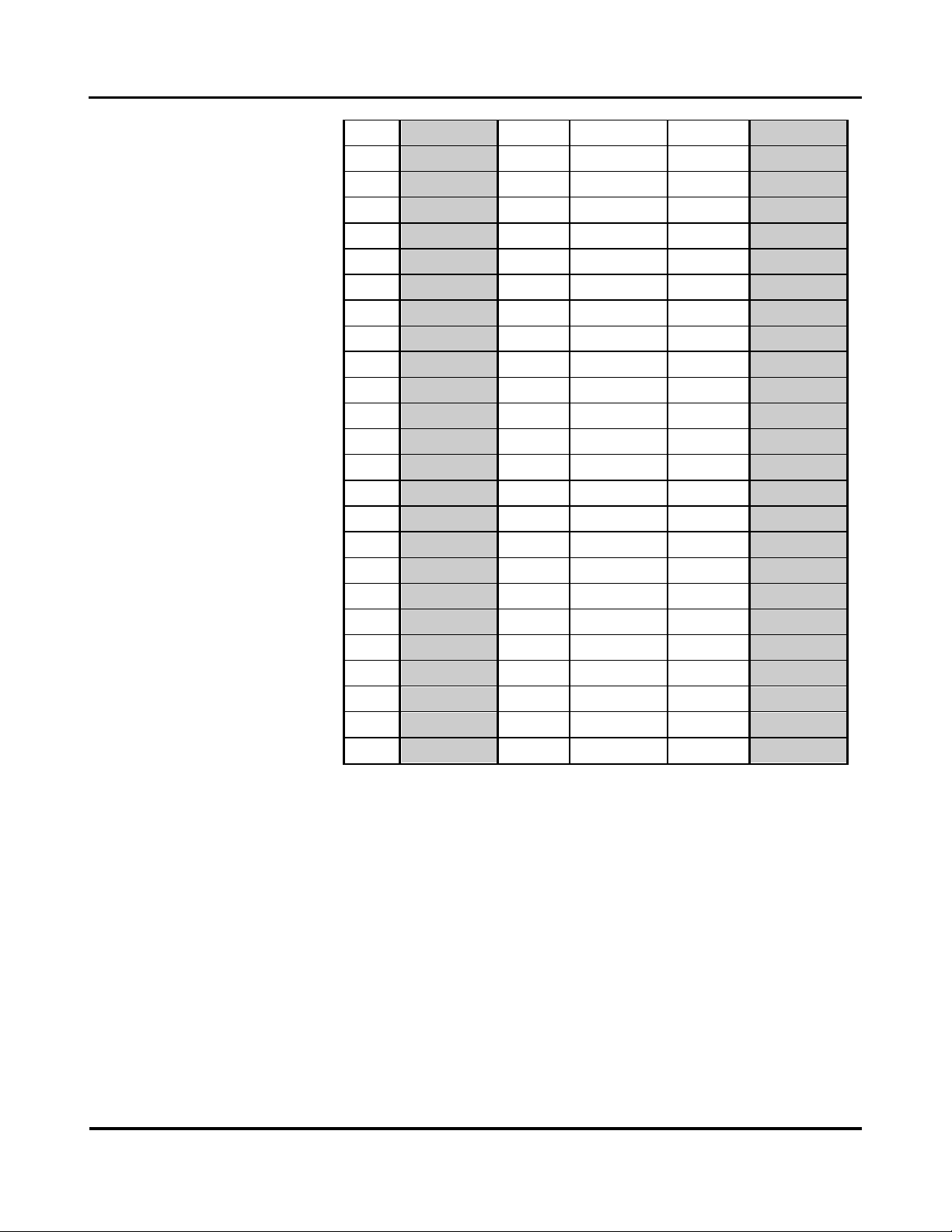
2.11 VME64x bus Connections
Table 2.3 indicates the pin assignments for the VME64x bus signals at the P1
connector. The P1 connector is the upper rear connector on the
AVME9670A board, as viewed from the front. The connector consists of 32
rows of five pins labeled A, B, C, D and Z. Pin Z1 is located at the upper
right-hand corner of the connector if the board is viewed from the front
component side.
Refer to the VME64x bus specification for additional information on the
VME64x bus signals.
Table 2.3 VMEbus P1 CONNECTIONS
Pin
Row Z
Row A
Row B
Row C
Row D
1
MPR
D00
BBSY*
D08
VPC
2
GND
D01
BCLR*
D09
GND
3
MCLK
D02
ACFAIL*
D10
+V1
4
GND
D03
BG0IN*
D11
+V2
5
MSD
D04
BG0OUT*
D12
RsvU
6
GND
D05
BG1IN*
D13
-V1
7
MMD
D06
BG1OUT*
D14
-V2
INDUSTRIAL I/O PACK SERIES
AVME9675A
VME64x bus 6U CARRIER BOARD
Acromag, Inc. Tel: 248-295-0310 - 16 -
http://www.acromag.com
- 16 -
https://www.acromag.com
8
GND
D07
BG2IN*
D15
RsvU
9
MCTL
GND
BG2OUT*
GND
GAP*
10
GND
SYSCLK
BG3IN*
SYSFAIL*
GA0*
11
RESP*
GND
BG3OUT*
BERR*
GA1*
12
GND
DS1*
BR0*
SYSRESET*
+3.3V
13
RsvBus
DS0*
BR1*
LWORD*
GA2*
14
GND
WRITE*
BR2*
AM5
+3.3V
15
RsvBus
GND
BR3*
A23
GA3*
16
GND
DTACK*
AM0
A22
+3.3V
17
RsvBus
GND
AM1
A21
GA4*
18
GND
AS*
AM2
A20
+3.3V
19
RsvBus
GND
AM3
A19
RsvBus
20
GND
IACK*
GND
A18
+3.3V
21
RsvBus
IACKIN*
SERA
A17
RsvBus
22
GND
IACKOUT*
SERB
A16
+3.3V
23
RsvBus
AM4
GND
A15
RsvBus
24
GND
A07
IRQ7*
A14
+3.3V
25
RsvBus
A06
IRQ6*
A13
RsvBus
26
GND
A05
IRQ5*
A12
+3.3V
27
RsvBus
A04
IRQ4*
A11
LI/I*
28
GND
A03
IRQ3*
A10
+3.3V
29
RsvBus
A02
IRQ2*
A09
LI\O*
30
GND
A01
IRQ1*
A08
+3.3V
31
RsvBus
-12V
+5VSTDBY
+12V
GND
32
GND
+5V
+5V
+5V
VPC
Asterisk (*) is used to indicate an active-low signal.
Shaded area are pins defined under the VME64 bus specification.
BOLD ITALIC Logic Lines are NOT USED by the carrier board.
() = Elongated (mate first, break last) connector contact.
Table 2.4 indicates the pin assignments for the VME64x bus signals at the P2
connector. The P2 connector is the lower rear connector on the
AVME9670A board, as viewed from the front. The connector consists of 32
rows of five pins labeled A, B, C, D and Z. Pin Z32 is located at the lower
right hand corner of the connector if the board is viewed from the front
component side.

INDUSTRIAL I/O PACK SERIES
AVME9675A
VMEx64 bus 6U CARRIER BOARD
Acromag, Inc. Tel: 248-295-0310 - 17 -
http://www.acromag.com
- 17 -
https://ww.acromag.com
TABLE 2.4: VME64x bus
P2 CONNECTIONS
Pin
Row Z
Row A
Row B
Row C
Row D
1
C46
B41
Not Used
B42
C47
2
GND
B43
Not Used
B44
C48
3
C49
B45
Not Used
B46
C50
4
GND
B47
Not Used
B48
B1
5
B2
B49
Not Used
B50
B3
6
GND
A1
Not Used
A2
B4
7
B5
A3
Not Used
A4
B6
8
GND
A5
Not Used
A6
B7
9
B8
A7
Not Used
A8
B9
10
GND
A9
Not Used
A10
B10
11
B11
A11
Not Used
A12
B12
12
GND
A13
Not Used
A14
B13
13
B14
A15
Not Used
A16
B15
14
GND
A17
Not Used
A18
B16
15
B17
A19
Not Used
A20
B18
16
GND
A21
Not Used
A22
B19
17
B20
A23
Not Used
A24
B21
18
GND
A25
Not Used
A26
B22
19
B23
A27
Not Used
A28
B24
20
GND
A29
Not Used
A30
B25
21
B26
A31
Not Used
A32
B27
22
GND
A33
Not Used
A34
B28
23
B29
A35
Not Used
A36
B30
24
GND
A37
Not Used
A38
B31
25
B32
A39
Not Used
A40
B33
26
GND
A41
Not Used
A42
B34
27
B35
A43
Not Used
A44
B36
28
GND
A45
Not Used
A46
B37
29
B38
A47
Not Used
A48
B39
30
GND
A49
Not Used
A50
B40
31
Not Used
Not Used
Not Used
Not Used
Not Used
32
GND
Not Used
Not Used
Not Used
Not Used
Note: The letter in front of the number identifies the IP Module
Slot. The number identifies the I/O pin number of that IP Module.

INDUSTRIAL I/O PACK SERIES
AVME9675A
VME64x bus 6U CARRIER BOARD
Acromag, Inc. Tel: 248-295-0310 - 18 -
http://www.acromag.com
- 18 -
https://www.acromag.com
Table 2.5 VME64x bus P0
CONNECTIONS
Example: C46 C = IP Module in Slot “C”
46 = I/O Pin number “46”
(This pin on the IP Module connects to P2, Pin 1, Row Z.)
Shaded area are pins defined under the VME64x bus specification.
BOLD ITALIC Logic Lines are NOT USED by the carrier board.
() = Elongated (mate first, break last) connector contact.
The I/O signals for the P2 connector are mapped per the IP Module I/O to
VME64x bus Standard (ANSI/VITA 4.1-1996). Refer to this standard for
additional information on the VME64x bus signals.
Table 2.5 lists the pin assignments for the VME64x bus signals at the P0
connector. The P0 connector is the center connector on the AVME9670A
board, as viewed from the front. The connector consists of 6 rows of 19
pins labeled A, B, C, D, E, and F. Pin A1 is located at the upper right hand
corner of the connector near the center of the board, viewed from the front
component side.
The I/O signals for the P0 connector are mapped per the IP Module I/O to
VME64Xbus Standard (ANSI/VITA 4.1-1996). Refer to this standard for
additional information on the VME64x bus signals.
Pin
Row A
Row B
Row C
Row D
Row E
Row F
1
D1
D2
D3
D4
D5
GND
2
D6
D7
D8
D9
D10
NP
3
D11
D12
D13
D14
D15
GND
4
D16
D17
D18
D19
D20
NP
5
D21
D22
D23
D24
D25
GND
6
D26
D27
D28
D29
D30
NP
7
D31
D32
D33
D34
D35
GND
8
D36
D37
D38
D39
D40
NP
9
D41
D42
D43
D44
D45
GND
10
D46
D47
D48
D49
D50
NP
11
C1
C2
C3
C4
C5
GND
12
C6
C7
C8
C9
C10
NP

INDUSTRIAL I/O PACK SERIES
AVME9675A
VMEx64 bus 6U CARRIER BOARD
Acromag, Inc. Tel: 248-295-0310 - 19 -
http://www.acromag.com
- 19 -
https://ww.acromag.com
13
C11
C12
C13
C14
C15
GND
14
C16
C17
C18
C19
C20
NP
15
C21
C22
C23
C24
C25
GND
16
C26
C27
C28
C29
C30
NP
17
C31
C32
C33
C34
C35
GND
18
C36
C37
C38
C39
C40
NP
19
C41
C42
C43
C44
C45
GND
Note: The letter in front of the number identifies the IP Module
Slot. The number identifies the I/O pin number of that IP Module.
Example: D1 D = IP Module in Slot “D”
1 = I/O Pin number “1”
(This pin on the IP Module connects to P0, Pin 1, Row A.)
(NP) = No Pin for PO connector (Row F is for upper ground shield).
2.12 POWER UP TIMING AND LOADING
The AVME9670A board uses a Field Programmable Gate-Array (FPGA) to
handle the bus interface and control logic timing. Upon power-up, the FPGA
automatically clocks in configuration vectors from a local PROM to initialize
the logic circuitry for normal operation. This time is measured as the first
145mS (typical) after the +5 Volt supply rises to +2.5 Volts at power-up. The
VME64x bus specification requires that the bus master drive the system
reset for the first 200mS after power-up, thus inhibiting any data transfers
from taking place.
IP control registers are also reset following a power-up sequence, disabling
interrupts, etc. (see Section 3 for details).
2.13 DATA TRANSFER TIMING
VME64x bus data transfer time is measured from the falling edge of DSx* to
the falling edge of DTACK* during a normal data transfer cycle. Typical
transfer times are given in the following table.
This manual suits for next models
2
Table of contents


