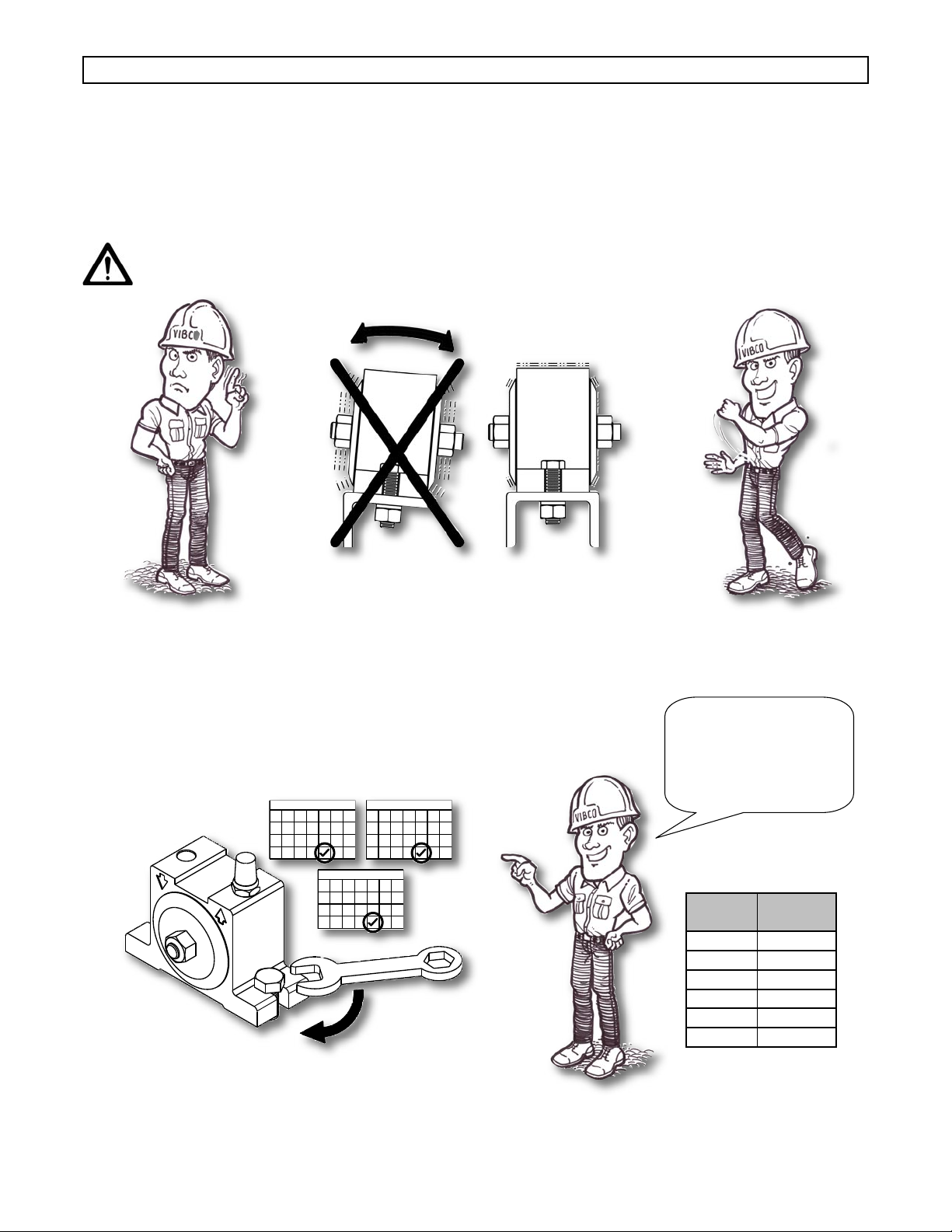
manuals.online logo
Brands
  1. Home
  2. •
  3. Brands
  4. •
  5. VIBCO
  6. •
  7. Industrial Equipment
  8. •
  9. VIBCO BBS-100 User manual

VIBCO BBS-100 User manual

This manual suits for next models

39

Other VIBCO Industrial Equipment manuals

VIBCO 100 - 130 User manual

VIBCO

VIBCO 100 - 130 User manual

VIBCO 2P-800 User manual

VIBCO

VIBCO 2P-800 User manual

VIBCO 50 User manual

VIBCO

VIBCO 50 User manual

VIBCO 2000 Series User manual

VIBCO

VIBCO 2000 Series User manual

VIBCO SCR User manual

VIBCO

VIBCO SCR User manual

VIBCO DC User manual

VIBCO

VIBCO DC User manual

Popular Industrial Equipment manuals by other brands

ABB +Q957 user manual

ABB

ABB +Q957 user manual

G.B.C BASIC EDGE 50 instruction manual

G.B.C

G.B.C BASIC EDGE 50 instruction manual

Tronair Batpak 11-6602-1000 Operation & service manual

Tronair

Tronair Batpak 11-6602-1000 Operation & service manual

Pilz PNOZ mi2p Operation manual

Pilz

Pilz PNOZ mi2p Operation manual

Clemco Zero BNP 6012 manual

Clemco

Clemco Zero BNP 6012 manual

Erskine Attachments V-Plow Operator's manual

Erskine Attachments

Erskine Attachments V-Plow Operator's manual

ABB HT610965 Operation manual

ABB

ABB HT610965 Operation manual

Morra MH 540 user manual

Morra

Morra MH 540 user manual

Eaton S090ST manual

Eaton

Eaton S090ST manual

GRIGGIO G 240 P4 instructions

GRIGGIO

GRIGGIO G 240 P4 instructions

Nexen AIR CHAMP HT45 user manual

Nexen

Nexen AIR CHAMP HT45 user manual

WTE V5 installation manual

WTE

WTE V5 installation manual

ABB HT845232 Operation manual

ABB

ABB HT845232 Operation manual

SMC Networks CJP Series Operation manual

SMC Networks

SMC Networks CJP Series Operation manual

JohnDow Industries JDI-AFT58 Operator's manual

JohnDow Industries

JohnDow Industries JDI-AFT58 Operator's manual

IMB MB9016A instruction manual

IMB

IMB MB9016A instruction manual

Clarke CUMB1 Assembly & operating instructions

Clarke

Clarke CUMB1 Assembly & operating instructions

amiad Arkal Spin Klin 2 user guide

amiad

amiad Arkal Spin Klin 2 user guide

manuals.online logo
manuals.online logoBrands
  • About & Mission
  • Contact us
  • Privacy Policy
  • Terms and Conditions

Copyright 2025 Manuals.Online. All Rights Reserved.

Corporate HQ & Factory:
75 Stilson Road Wyoming, RI 02898
Phone: 800 633-0032 (401) 539-2392
Fax: (401) 539-2584
Western US:
Phoenix, AZ 85254
Phone: 800 633-0032 (480) 596-1809
Fax: (480) 596-1614
Canada:
2215 Dunwin Drive
Mississauga, ONT L5L 1X1
Phone: 800 465-9709 (905) 828-4191
Fax: (905) 828-5015
E-mail: [email protected]
Website: www.vibco.com
Mounting Instructions • Operating Instructions • Technical Data
Parts List • Maintenance • Trouble Shooting
Pneumatic Turbine
Thank you for choosing VIBCO, Inc. for your vibration needs. You are now the owner of the
nest silent pneumatic vibrator available today backed by complete manufacturer condence in
its quality and dependability. For reference please complete the information below about your
new VIBCO vibrator.
Model Number: ____________________
Date of Purchase: ____________________
Safety Instructions .......................................................................................................................2
Mounting Instructions Checklist ...................................................................................................3
Mounting Procedures ................................................................................................................3-4
Mounting To Bin Walls Or Chutes.............................................................................................5-8
Vibrator Installation and Pneumatic Hook-up...........................................................................9-11
Operating Instructions ...............................................................................................................12
Technical Data and Dimensions
Model BBS and FBS........................................................................................................13
Model VS.........................................................................................................................14
Model BVS.......................................................................................................................15
Model MLT and MLTSS...................................................................................................16
Exploded Views & Parts List ................................................................................................17-20
Troubleshooting.................................................................................................................21
Warranty & General Information ................................................................................................22
TABLE OF CONTENTS
1
PHONE ORDER: 1-800-633-0032 FAX: 1-401-539-2584
WWW.VIBCO.COM [email protected]
WARNING: Failure to read and follow these installation instructions and safety
precautions could result in personal injury, equipment damage, shortened
service life or unsatisfactory equipment performance. All information in this
document is vital to the proper installation and operation of the equipment. It
is important that all personnel who will be coming in contact with this product
thoroughly read and understand this manual.
VIBCO turbine air vibrators are designed to keep noise pollution at a minimum. Compressed air
turns a specially designed turbine wheel that channels the air through the unit at frequencies well
above the human hearing range, making it virtually silent. Turbine vibrators average a whisper
quiet 72 dB. The BBS, BVS, MLT and MLTSS models should use a mufer to remove exhaust
air hiss. The VS model has a built-in mufer.
General Features
VIBCO turbine air vibrators operate in any position and are not adversely affected by dust, dirt
or wetness. Speed can be adjusted by varying the air supply pressure. The only moving part is
pre-lubricated for life and never needs oil, even for continuous duty.
SAFETY INSTRUCTIONS
HOW IT WORKS
2
PHONE ORDER: 1-800-633-0032 FAX: 1-401-539-2584
WWW.VIBCO.COM [email protected]
NOTE:
On BVS, BBS,
MLT & MHI
models, the smaller
INNER port is the air
inlet and the larger
INNER port is the
exhaust.
Optional Features For MLT Models
• Metric Threads
• Special Coatings:
• High gloss dairy white industrial enamel
• Anodized or unpainted aluminum
Mounting Plate
For force up to 100 lbs. use a 1/4 in. thick plate, 100 to 500 lbs. use a 3/8 in. to 1/2 in. thick plate and over
500 lbs. use a 1/2 in. thick plate.(See Table).
Mounting Channel
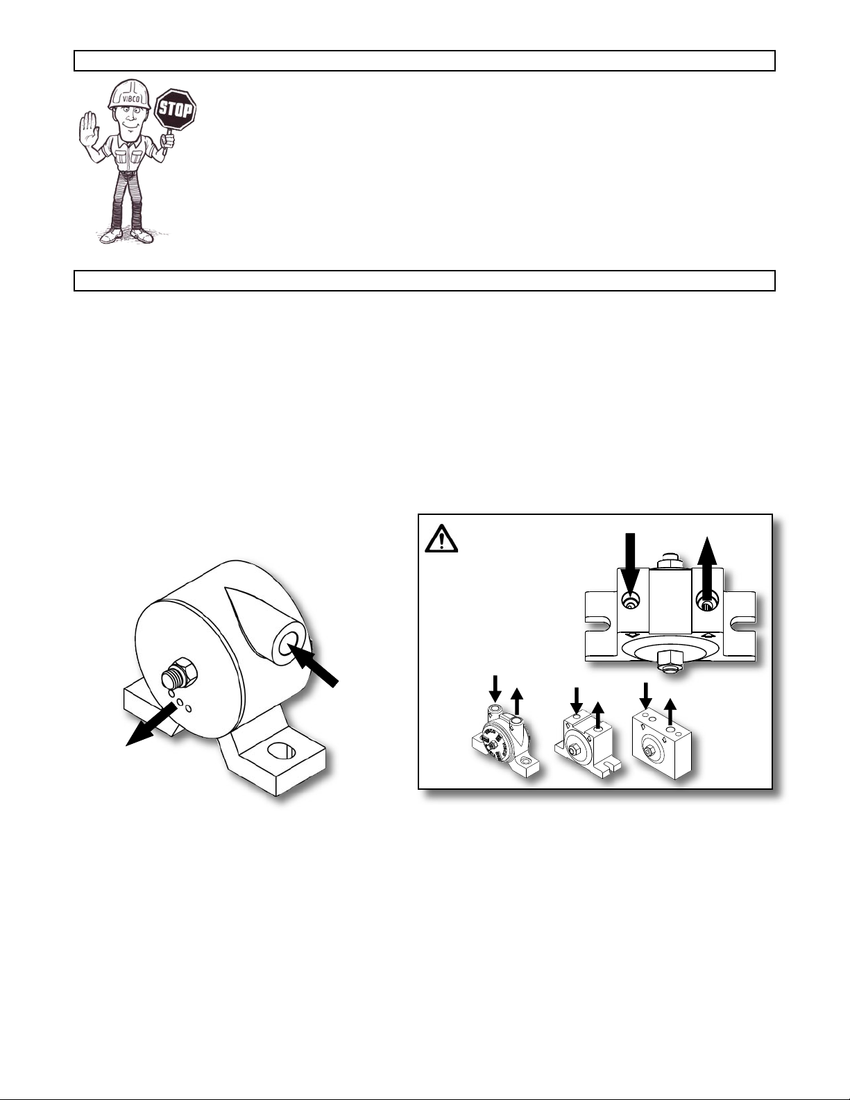
Never place the vibrator directly onto the skin of the bin. It should be mounted to either a plate or a piece
of channel iron that has been welded to the bin. The proper mounting method is to use either 3 in. or 4
in. channel iron. This will help to stiffen the structure to be vibrated as well as spread the vibration over a
larger surface, increasing the overall efciency and diminishing the possibilities of fatigue cracks in the bin
material.
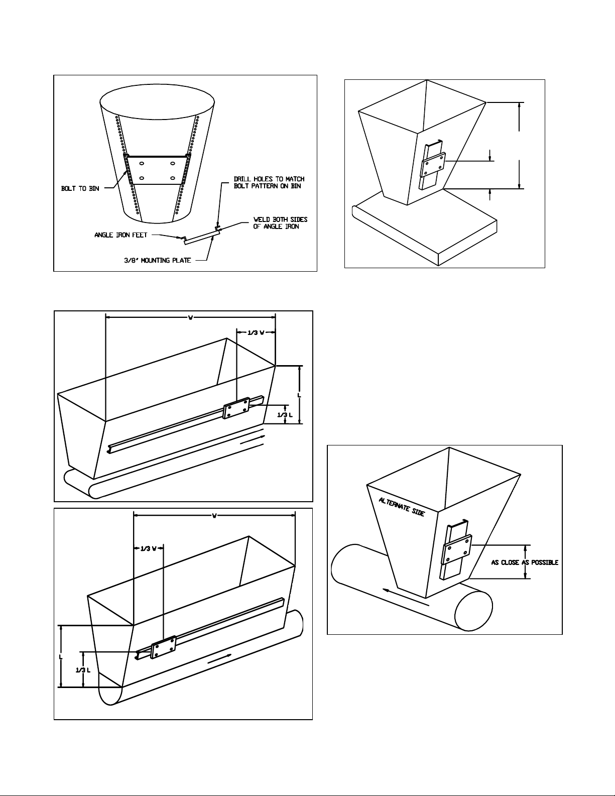
The length of the channel iron is determined by the thickness of the bin plate. For vibrators with a force up
to 500 lbs. and a bin plate under 3/16” the 4 in. channel iron should extend 18 to 36 inches on both sides
of the vibrator. For smaller vibrators with a force of up to 100 lbs. and a bin thickness of 3/16 in. to 1/4 in.
the length of the 3 in. channel iron should extend 3 to 4 inches on both sides of the vibrator. For vibrators
with a force between 100 and 500 lbs. and a bin thickness of 3/8 in. to 1/2 in. the length of the 3 in. or 4
in.channel iron should extend 6 to 8 inches on both sides of the vibrator. (See Table).
Warranty is void if vibrator is not properly installed. During installation follow and check off the
following steps and your vibrator should provide you with years of trouble-free service.
� Determine the length of the channel iron.
� Select thickness of vibrator mounting plate and method of mounting.
� STITCH weld mounting plate to channel iron.
� Determine where vibrator should be placed on the bin.
� STITCH weld channel iron to bin.
� Place vibrator on mounting plate. It is important that you check the
mounting plate for any warping. Secure vibrator rmly.
� Install safety chain or wire.
� Connecting pneumatics.
� Continuous vs. intermittent operation.
� FILL OUT WARRANTY CARD!!!
Mounting Instructions Checklist
3
PHONE ORDER: 1-800-633-0032 FAX: 1-401-539-2584
WWW.VIBCO.COM [email protected]
LBS. OF FORCE PLATE THICKNESS
up to 100 lbs. 1/4" plate
100 to 500 lbs. 3/8" to 1/2" plate
over 500 lbs. 1/2" plate
CORRECT MOUNTING PLATES
SUGGESTED CHANNEL LENGTH
LBS. OF FORCE/BIN WALL WIDTH CHANNEL IRON WIDTH CHANNEL IRON LENGTH
up to 100 lbs / bin wall < 3/16" (thin) 3" channel iron 18" to 36" on both sides of vibrator
up to 500 lbs / bin wall = 3/16" to 1/4" 4" channel iron 3" to 4" on both sides of vibrator
over 500 lbs / bin wall = 3/8" to 1/2" 4" channel iron 6" to 8" on both sides of vibrator
If you have any questions consult the Mounting Instruction section of this manual or call
VIBCO’s Technical Support at (800) 633-0032.
MOUNTING INSTRUCTIONS
Different Suggestions for Mounting the Channel
1. Mounting plate welded to legs of channel iron.
2. 3 in. or 4 in. channel iron with holes drilled thru and nuts welded on back side, or just holes
drilled thru.
3. Add mounting plate and drill and tap holes thru.
4. Notch the channel for access to mounting bolts.
5. Weld studs to back of channel.
Always stop welds 1 in. from ends to prevent cracks.
NOTE: for a list of alternate and special application brackets, see pg. 35 of the VIBCO General Catalog.
Placement
For coarse materials the vibrator should be mounted approximately 1/3 of the distance from
the discharge opening to the top of the sloped portion of the bin. For ne grain materials place
the vibrator approximately 1/4 of the same distance (see different mounting suggestions on the
following pages).
Welding Channel Iron To Bin
Where possible the mounting plate on the channel iron should be placed 1/3 to 1/4 of the distance
from the discharge opening to the top of the sloped portion of the bin. Stitch weld channel iron
in place, then weld intermittent welds 3 to 6” long with 3” between them along the entire length
of the channel. Stop weld a minimum of 1” from the ends, it is important that you do not weld
the ends of the channel iron. The heat concentration when welding the ends could cause the
beginning of fatigue cracks.
Installing Safety Chain
It is important to install a safety chain or wire in order to prevent the vibrator from falling and
potentially causing injury if it comes loose from its mount.
1 5
43b
3a
2
4
PHONE ORDER: 1-800-633-0032 FAX: 1-401-539-2584
WWW.VIBCO.COM [email protected]
Welding Mounting Plate to Channel Iron
Weld the mounting plate to the middle of the channel iron. If the bin plate is 3/16 in. or less, weld
the mounting plate to the back of the channel iron (see gure 3 or 4). If the bin plate is over 3/16
in. weld the mounting plate to the legs of the channel iron (see gure 1). Drill and tap holes or
use studded plate (see gure 1).Make sure the mounting plate does not warp or distort. If this
occurs, straighten, replace it or shim up vibrator.
Mounting Suggestions
Conical Bin Rectangular Bin
1/2 Rectangular Bin
One Vibrator For A Double Bin
Bin With Stiffeners
Angle Iron Stiffeners
Instead of Channel Iron
Thin Skinned Bin
Corner Mount
5
1/2 L
1/3 L
L
Two Vibrators On
A Single Bin
PHONE ORDER: 1-800-633-0032 FAX: 1-401-539-2584
WWW.VIBCO.COM [email protected]
Sheet Metal Bin Belt Conveyor and
Standard Bin
Long Bin
Belt conveyor feeds from the front. Vibrator
should be placed 1/3 from the front. If 2
vibrators are used, place 2nd one directly
opposite 1/3 from the back. Do not operate
back vibrator until bin is empty in front and
the front vibrator has turned off. For more
details consult Vibco.
Feeds from back. Vibrator should be placed
1/3 from the back. If 2 vibrators are used,
place 2nd one directly opposite 1/3 from the
front. Do not operate front vibrator until bin
is empty in back and the back vibrator has
turned off. For more details consult Vibco.
6
Belt Conveyors
Screw Conveyors
PHONE ORDER: 1-800-633-0032 FAX: 1-401-539-2584
WWW.VIBCO.COM [email protected]
1/3 L
L
Heat Mounts for Insulated Bins Containing High Temperature Materials
When materials in the bin have a temperature over 150oF, it is advisable to use a “heat” mount to prevent excessive
heat from reaching the vibrator causing overload or bearing failure. Also ask for “high” temperature grease in
vibrator bearing. Consult VIBCO for vibrator size.
Use steel plate on inside and bolt to outside
mounting channel.
Mount steel plate on inside of bin so that the
vibrator sits 1/3 up bin side. Isolate the plate from
the concrete by using vibration shock absorbers.
Consult VIBCO for detailed drawings.
7
PHONE ORDER: 1-800-633-0032 FAX: 1-401-539-2584
WWW.VIBCO.COM [email protected]
CHUTES
In order to successfully move material in a chute, the “angle of repose” of the material has to be
known. It can be found in most handbooks or can easily be measured by pouring a cup of the
material on a table. The angle between the table and the cone the material makes is the “angle
of repose”. To move the material in the chute, it should be inclined no less than 1/2 of the “angle
of repose” If this cannot be obtained, a feeder is necessary to move the material. (A) Chutes
up to 6 ft. are generally handled by one vibrator mounted approximately 1/3 from the discharge.
(B) On chutes over 6 ft. long, two vibrators are needed, one should be placed 18/-24” from the
discharge. The other approximately in the middle. Since chutes are very sensitive to vibration,
provision should be made to move the lower vibrator 6 inches in either direction. This could
mean the difference between moving the material or not moving it. (C) The direction of rotation
of the vibrator shaft should be in the direction of material ow. (D) Force (impact) needed on
vibrator is equal to weight of chute + vibrator + max material in chute. Chutes must have an
inclination of at least 10o for vibrators to be able to move the material. If inclination is less the
chute has to be made into a feeder. Contact VIBCO for selecting the proper size vibrator or ask
for the bulletin covering chutes.
8
PHONE ORDER: 1-800-633-0032 FAX: 1-401-539-2584
WWW.VIBCO.COM [email protected]
9
PHONE ORDER: 1-800-633-0032 FAX: 1-401-539-2584
WWW.VIBCO.COM [email protected]



Installation of the Vibrator
It is now time to put the VIBCO vibrator in place. Make sure that it is secured tightly. Retighten
the bolts after the rst 10 to 15 minutes of operation and check them periodically to maintain
proper tightness (gures 1 and 2).
VIBRATOR INSTALLATION
Damage to the bin and the vibrator can occur if not mounted securely.
Remember:
Check those
bolts!
BOLT
SIZE
TORQUE
ft-lbs
1/4" 13
5/16" 25
3/8" 48
1/2" 115
5/8" 145
3/4" 260
FIGURE 1
FIGURE 2