Acromag ARCX 4000 Series User manual

Artisan Technology Group is your source for quality
new and certied-used/pre-owned equipment
• FAST SHIPPING AND
DELIVERY
• TENS OF THOUSANDS OF
IN-STOCK ITEMS
• EQUIPMENT DEMOS
• HUNDREDS OF
MANUFACTURERS
SUPPORTED
• LEASING/MONTHLY
RENTALS
• ITAR CERTIFIED
SECURE ASSET SOLUTIONS
SERVICE CENTER REPAIRS
Experienced engineers and technicians on staff
at our full-service, in-house repair center
WE BUY USED EQUIPMENT
Sell your excess, underutilized, and idle used equipment
We also offer credit for buy-backs and trade-ins
www.artisantg.com/WeBuyEquipment
REMOTE INSPECTION
Remotely inspect equipment before purchasing with
our interactive website at www.instraview.com
LOOKING FOR MORE INFORMATION?
Visit us on the web at www.artisantg.com for more
information on price quotations, drivers, technical
specications, manuals, and documentation
Contact us: (888) 88-SOURCE | sales@artisantg.com | www.artisantg.com
SM
View
Instra
ARCX 4000 Series
Ruggedized/Military/Industrial Computer
USER’S MANUAL
ACROMAG INCORPORATED
30765 South Wixom Road
Wixom, MI 48393-7037 U.S.A.
Tel: (248) 295-0310
Fax: (248) 624-9234
Copyright 2015, Acromag, Inc., Printed in the USA.
Data and specifications are subject to change without notice.
8501-025G

ARCX 4000 SERIES
USER’S MANUAL
- 1 -
www.acromag.com
Table of Contents
1.0 GENERAL INFORMATION................................................................................................. 5
1.1 Intended Audience .......................................................................................................5
1.2 Preface.........................................................................................................................5
1.2.1 Trademark, Trade Name and Copyright Information .................................................................. 5
1.2.2 Class A Product Warning............................................................................................................. 5
1.2.3 Environmental Protection Statement ......................................................................................... 5
1.3 ARCX 4000 Series..........................................................................................................6
1.3.1 Key Features............................................................................................................................... 6
CPU Module (XCOM-6400).................................................................................................................... 7
Chipset.................................................................................................................................................. 7
Memory................................................................................................................................................ 7
1.4 Ordering Information ....................................................................................................8
1.4.1 Accessories..................................................................................................................................10
1.5 References .................................................................................................................12
1.6 Operating System Compatibility .................................................................................12
2.0 PREPARATION FOR USE.................................................................................................13
2.1 Unpacking and Inspecting...........................................................................................13
3.0 BLOCK DIAGRAMS AND CONNECTOR PIN OUT TABLES............................................14
3.1 ARCX-4120 Block Diagrams ........................................................................................14
3.1.1 XCOM-6400 COM Express CPU Module Block Diagram ........................................... 14
3.1.2 Model ACEX-4620 Carrier Block Diagram ................................................................. 15
3.1.3 Model ACEX-FP-02 Front Panel (standard) Block Diagram ...................................... 16
3.1.4 ARCX-4120, Top view ............................................................................................... 17
3.1.5 ARCX-4120, Bottom view ......................................................................................... 18
3.2 ARCX-4110 Block Diagrams ........................................................................................19
3.2.1 XCOM-6400 COM Express CPU Module Block Diagram ........................................... 19
3.2.2 Model ACEX-4610 Carrier Block Diagram ................................................................. 20
3.2.3 Model ACEX-FP-01 Front Panel (standard) Block Diagram....................................... 21
3.2.4 ARCX-4110, Top view ............................................................................................... 22
3.2.5 ARCX-4110, Bottom view ......................................................................................... 23

ARCX 4000 SERIES
USER’S MANUAL
- 2 -
www.acromag.com
3.3 Connector Pin Outs.....................................................................................................24
J3 - Keyed-A (130-Pin size #23 38999 type Connector)........................................................ 24
J4 - Keyed-B (130-Pin size #23 38999 type Connector) ........................................................ 25
J5 - Keyed-C (130-Pin size #23 38999 type Connector) ........................................................ 26
J6 - Keyed-A (6-Pin size #12 38999 type Connector)............................................................ 27
4.0 LED FUNCTION ................................................................................................................. 27
4.1 Power LED ....................................................................................................................................27
4.2 Status LED ....................................................................................................................................27
4.3 System power state definitions ....................................................................................................28
5.0 SWITCH CONFIGURATION............................................................................................29
5.1 8-Position Dip switch (located on the Carrier board) ...................................................................29
6.0 INSTALLING EXPANSION MODULES, MEMORY AND BATTERY.........................31
6.1 ARCX-4110, disassembly...............................................................................................31
6.2 ARCX-4120, disassembly...............................................................................................33
6.3 ARCX-4110, installing a PMC or XMC module................................................................35
6.4 ARCX-4120, installing a PMC or XMC module................................................................37
6.5 ARCX-4110 OR ARCX-4120, installing a Mini PCIe or mSATA module .............................40
6.6 ARCX-4110 or ARCX-4120, memory access....................................................................42
6.7 ARCX-4110 or ARCX-4120, battery access .....................................................................49
6.8 ARCX-4110, assembly ...................................................................................................51
6.9 ARCX-4120, assembly ...................................................................................................53
7.0 SERVICE AND REPAIR .....................................................................................................55
7.1 Service and Repair Assistance .....................................................................................55
7.2 Preliminary Service Procedure ....................................................................................55
7.3 Where to Get Help......................................................................................................55
8.0 SPECIFICATIONS............................................................................................................... 56
8.1 Physical ......................................................................................................................56

ARCX 4000 SERIES
USER’S MANUAL
- 3 -
www.acromag.com
Mechanical Dimensions ARCX-4110-XX ..............................................................................57
Mechanical Dimensions ARCX-4120-XX ..............................................................................58
Mechanical Dimensions ARCX-4111-XX ..............................................................................59
..........................................................................................................................................59
Mechanical Dimensions ARCX-4121-XX ..............................................................................60
8.2 Environmental Considerations......................................................................................61
8.2.1 Operating Temperature and Airflow Requirements ....................................................................61
8.3 Power Requirements....................................................................................................65
8.31 POWER ESTIMATION TABLES .......................................................................................................65
8.4 Other Environmental Requirements .............................................................................67
8.4.1 Relative Humidity........................................................................................................................67
8.4.2 Storage Temperature ..................................................................................................................67
8.4.3 Vibration (operating and Non-operating)....................................................................................67
8.4.4 Mechanical Shock (operating and Non-operating)............................................................. 67
8.4.5 Ingress Protection Water/Dust proof................................................................................. 67
8.4.6 CE Marked .......................................................................................................................... 68
8.4.7 FCC US/Canada ................................................................................................................... 68
8.5 Reliability Prediction ....................................................................................................68
APPENDIX .................................................................................................................................... 69
Programmable Power Limits ..............................................................................................69
Power Filter (Optional Accessory) installation ....................................................................71
Features ...............................................................................................................................71
Specification Compliance .....................................................................................................................71
Front Panel with Mezzanine Option ...................................................................................75
Mezzanine Board Interface ..................................................................................................................75
Model ACEX-FP-IO-0x Front Panel with Mezzanine Block Diagram ......................................................76
Replacing mezzanine boards................................................................................................................77
Dual SSD Drive Bay Option.................................................................................................79
Dual SSD Drive Bay Option - SSD (Solid State Drive) Installation ..........................................................82
ATMD-02 Air Cooled Heatsink............................................................................................83
ATMD-03 Cold Plate...........................................................................................................84

ARCX 4000 SERIES
USER’S MANUAL
- 4 -
www.acromag.com
CERTIFICATE OF VOLATILITY...............................................................................................85
REVISION HISTORY...................................................................................................................86

ARCX 4000 SERIES
USER’S MANUAL
- 5 -
www.acromag.com
1.0 GENERAL INFORMATION
1.1 Intended Audience
This user’s
manual was written for technically qualified personnel who will be
working with
ARCX series devices using the XCOM-6400 COM Express
module
. It is not intended for a general, non-technical audience that is
unfamiliar
with computer-on-module (COM) devices and their application.
1.2 Preface
The information contained in this manual is sub
ject to change without notice,
and Acromag
, Inc. (Acromag) does not guarantee its accuracy. Acromag
makes no warranty of any kind with regard to this material, including, but not
limited to, the implied warranties of merchantability and fitness for a
particular p
urpose. Further, Acromag assumes no responsibility for any
errors that may appear in this manual and makes no commitment to update,
or keep current, the information contained in this manual. No part of this
manual may be copied or reproduced in any form, without the prior written
consent
of Acromag,
1.2.1 Trademark, Trade Name and Copyright Information
© 201
5 by Acromag Incorporated.
All rights reserved. Acromag and Xembedded are registered trademarks of
Acromag Incorporated. All other trademarks, registered trademarks, trade
names, and service marks are the property of their respective owners.
1.2.2 Class A Product Warning
This is a Class A product. In a domestic environment this product may cause
radio interference, in which case the user may find it necessary to take
adequate corrective measures.
1.2.3 Environmental Protection Statement
This product has been manufactured to satisfy environmental protection
requirements where possible. Many components used (structural parts,
circuit boards, connectors, batteries, etc.) are capable of being recycled.
Final disposition of this product after its service life must be conducted in
accordance with applicable country, state, or local laws or regulations.

ARCX 4000 SERIES
USER’S MANUAL
- 6 -
www.acromag.com
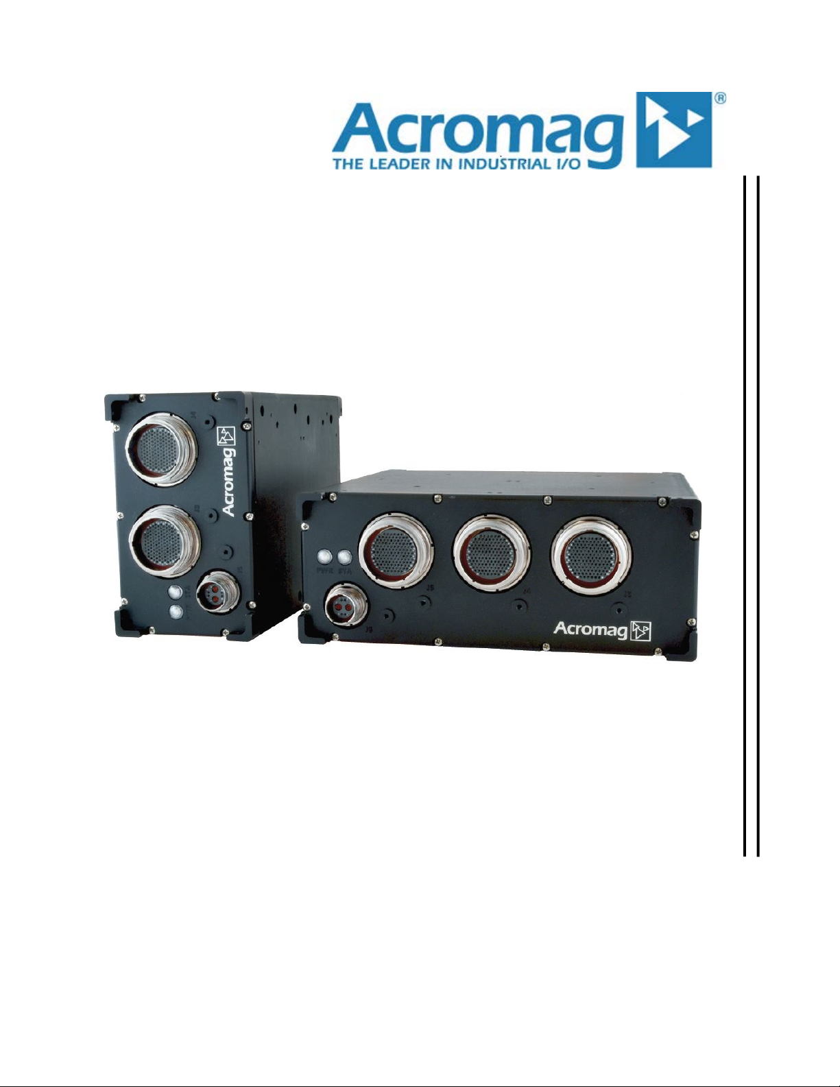
1.3 ARCX 4000 Series
The ARCX 4000 Series offers Ruggedized/Military/Industrial Computer for
the Acromag Com Express processor modules. There are two basic model
types, ARCX-4120 and ARCX-4110. The ARCX-4120 offers two PMC/XMC
expansion sites. The ARCX-4110 offers one PMC/XMC expansion site.
The ARCX 4000 series has the following options:
•Expansion size
•Dual Drive Bay
•Power Filter
•Front Panel
1.3.1 Key Features
•Designed to meet requirements of MIL-STD-810F environmental
specification.
•Designed to meet IP67 NEMA Rating.
•Optional Power Filter to meet requirements of MIL-STD-704F
and MIL-STD-1275E.
•Programmable Power Limits.
•Wide range input power, 10Vdc-36Vdc through a Size #12
38999 Type connector.
•Power indicator and fault/Status LEDs.
•Supports Acromag Type 6 COM CPU modules.
•Provides access to standard computer peripherals of the Type 6
COM Express CPU module through size #23 38999 Type
connector.
oTwo HDMI/DVI ports
oOne VGA port
oThree USB 2.0 Ports
oTwo RS-232/485 Communication ports
oOne SATA port
oTwo Gigabit Ethernet Ports
oAudio (One Line in and One Line out)
oFault/Status LED

ARCX 4000 SERIES
USER’S MANUAL
- 7 -
www.acromag.com
•Two mPCIe/mSATA slots are available on the carrier.
•PMC/XMC expansion (Option of one or two sites)
oPMC/XMC Rear I/O access provided through the front
of the ARCX 4000 via MIL-STD #23 38999 type
connector.
oPMC/XMC Front I/O access available through the rear
panel of the ARCX 4000.
Pocket and PMC/XMC cutout outline indicated
on rear panel
IP67 rating voided when hole is cut out
•Dual SSD Drive Bay (Option)
o
Two SATA SSD Drive Bays (2.5 inch drive’s supported)
CPU Module (XCOM-6400)
Intel Core™ i7 processor (4th generation, codename Haswell)
i7-4700EQ: 2.4GHz, quad core, 6Mb cache, 47W.
Chipset
Intel 8-Series QM87 PCH chipset (codename Lynx Point)
Intel DH82QM87 Platform Controller Hub
Memory
16GB of 1600 DDR3L ECC memory (see section 6.6 for more information)

ARCX 4000 SERIES
USER’S MANUAL
- 8 -
www.acromag.com
1.4 Ordering Information
Models:
ARCX4_ _ _ - _ _
Example:
ARCX-4120-PF (i7 CPU, Double PMC/XMC Expansion size, Power Filter)
CPU
1 = i7
Expansion size
1 = Single PMC/XMC
2 = Double PMC/XMC
Drive Bay
0 = Standard (No Bay)
1 = Dual SSD Drive Bay
Options
00 = Standard
PF = Power Filter
01 = Front Panel with Mezzanine
XX = Reserved
Only Lead Free models are available.
Note: Customers requiring lead solder electronics in the ARCX box will be handled as a special with
appropriate NRE to cover cost of documenting and lead-time to build.
ARCX 4000 SERIES
USER’S MANUAL
- 9 -
www.acromag.com
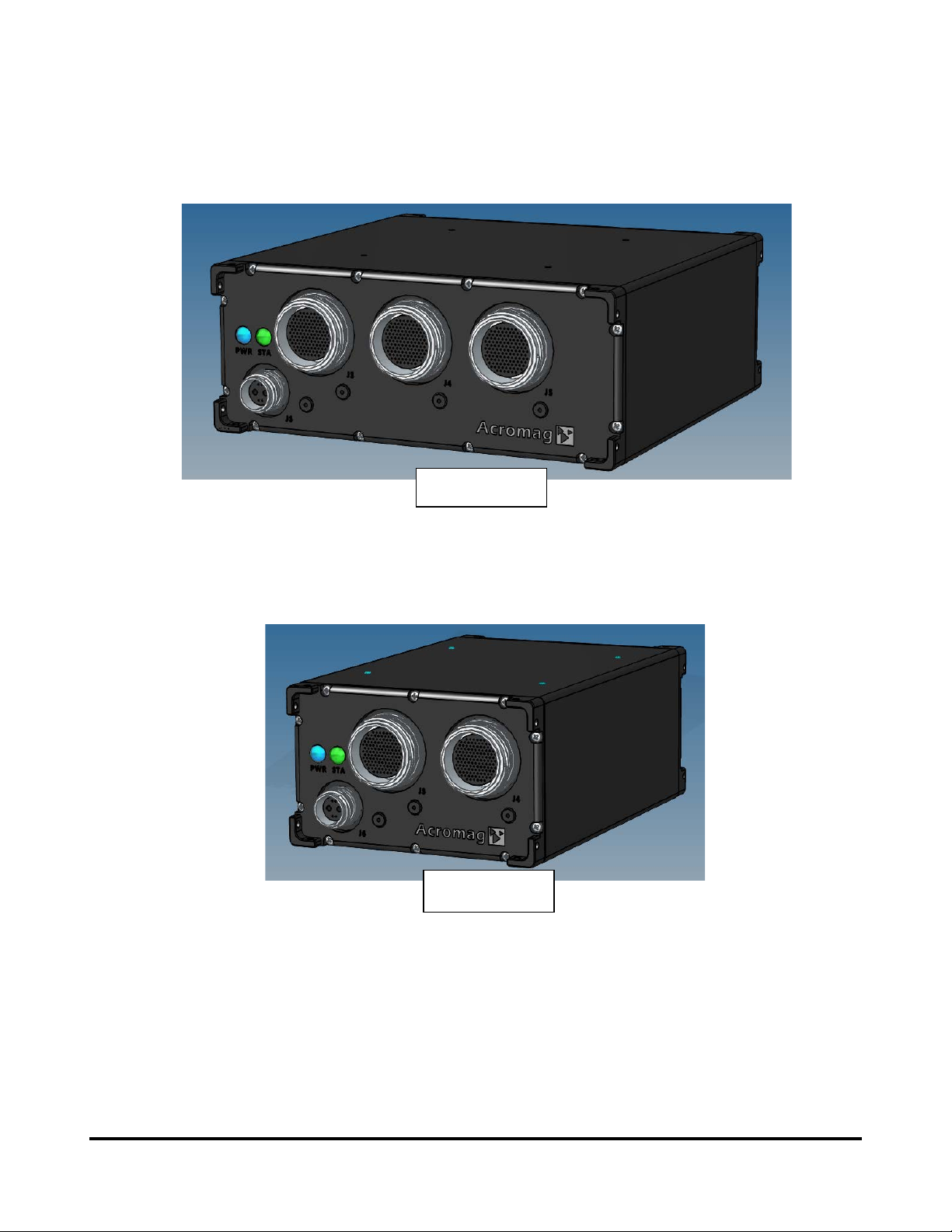
ARCX-4120-00
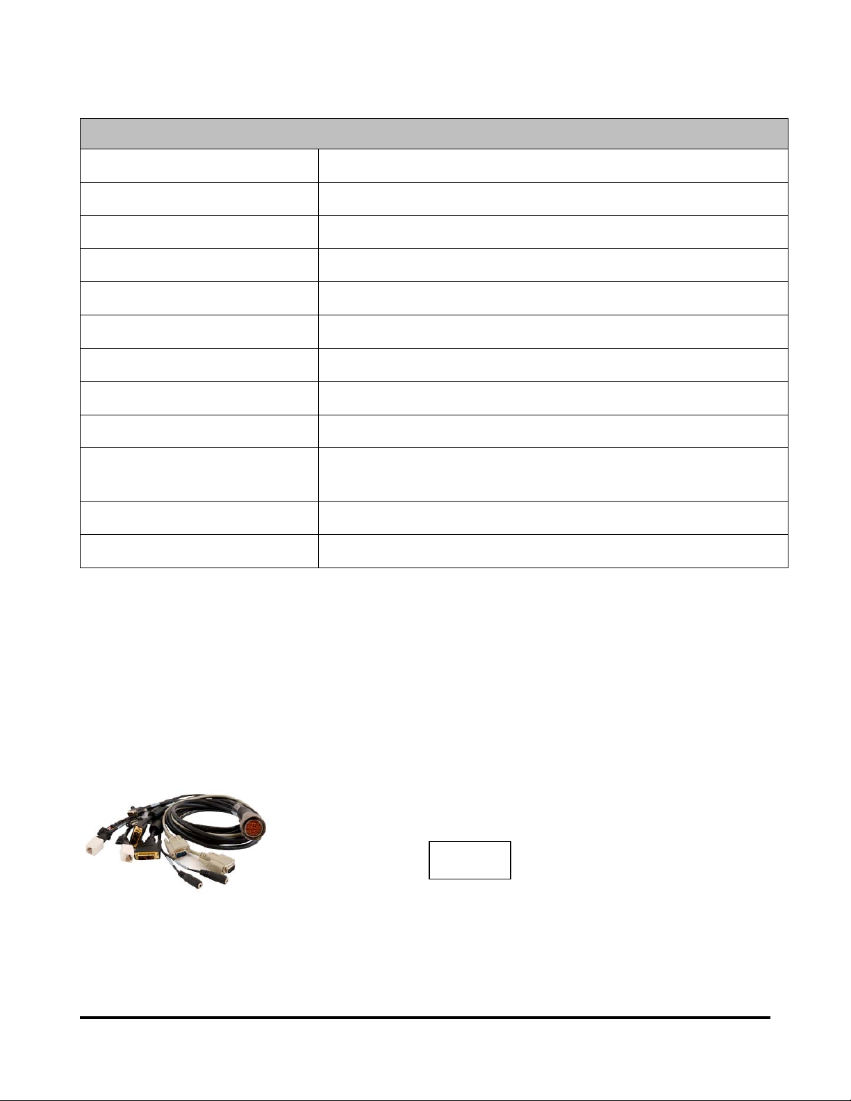
ARCX-4110-00
ARCX 4000 SERIES
USER’S MANUAL
- 10 -
www.acromag.com
1.4.1 Accessories
Accessories (optional)
ACEX-FP-PF-LF MIL-STD-704F/MIL-STD-1275E Power Filter
5028-556 38999 #23 size, CPU I/O Peripheral Breakout Cable
5028-557 38999 #12 size, Power Cable
5028-558 38999 #23 size Keyed “A” mating cable connector only
5028-559 38999 #23 size Keyed “C” mating cable connector only
5028-560 38999 #23 size Keyed “B” mating cable connector only
5028-561 38999 #12 size Keyed A mating cable connector only
5028-566 38999 #23 size, PMC/XMC Site 1 Rear I/O Breakout Cable
5028-567 38999 #23 size, PMC/XMC Site 2 Rear I/O Breakout Cable
5028-571 ARCX Dual SSD Drive Tray (Spare Drive Tray for Dual SSD Dive Bay
Option)
ATMD-02 Air cooled heatsink
ATMD-03 Cold Plate, 8” x 10” Assembly
Note: The cables/connectors in the table above are for development and are not IP67 rated.
Note: 5028-566 and 5028-567 cables are intended for use with two 5025-288 SCSI-3 termination panels.
5028-556

ARCX 4000 SERIES
USER’S MANUAL
- 11 -
www.acromag.com
Customers that need IP67 cables can use the following connectors/boots that are available thru Amphenol or
Aero Electric:
Amphenol Part Number Connector Description Straight Shrink boot
Part number
Right Angle Shrink
boot Part number
2M805-002-16ZNU23-
130PA
CONN P CIR 130 38999 #23 keyed A
PLUG IP67
2M809S060-6H 2M809A060-6H
2M805-002-16ZNU23-
130PB
CONN P CIR 130 38999 #23 keyed B
PLUG IP67
2M809S060-6H 2M809A060-6H
2M805-002-16ZNU23-
130PC
CONN P CIR 130 38999 #23 keyed C
PLUG IP67
2M809S060-6H 2M809A060-6H
2M805-002-16ZNU12-
201PA
CONN P 6 CIR 38999 #12 Keyed A
PLUG IP67
2M809S060-4H 2M809A060-4H
Aero Electric Part Number Connector Description Straight Shrink boot
Part number
Right Angle Shrink
boot Part number
AE96MM-26-Y23-130PA-
002
Ultra High Density 38999 III plug,
shell size 23, integral rear, normal/A
clocking
AE94MM-809S060-6H AE94MM-809A060-6H
AE96MM-26-Y23-130PB-
002
Ultra High Density 38999 III plug,
shell size 23, integral rear,
alternate/B clocking
AE94MM-809S060-6H AE94MM-809A060-6H
AE96MM-26-Y23-130PC-
002
Ultra High Density 38999 III plug,
shell size 23, integral rear,
alternate/C clocking
AE94MM-809S060-6H AE94MM-809A060-6H
AE96MM-26-Y12-201PA-
002
Ultra High Density 38999 III plug,
shell size 12, integral rear, normal/A
clocking
AE94MM-809S060-4H AE94MM-809A060-4H

ARCX 4000 SERIES
USER’S MANUAL
- 12 -
www.acromag.com
1.5 References
The following
resources regarding COM Express modules, the XCOM-4600
EDK board, and the
Haswell© family of Intel® core processors are available
for download on Acromag’s website or by contacting your sales
representative.
XCOM-6400 COM Express CPU Module User’s Manual
www.acromag.com
APTIOTM Core BIOS Manual (for Acromag®Products featuring the
Intel®4th Generation “Haswell” Core Processor Family)
www.acromag.com
ACEX-4610/4620 COM Express Carrier Board User’s Manual
www.acromag.com
ACEX-FP-0X Front Panel Board User’s Manual
ACEX-FP-I0-0X Front Panel Board with Mezzanine User’s Manual
www.acromag.com
XCOM-4600-EDK Engineering Design Kit Board
www.acromag.com
Intel® document No. 328901, “Mobile 4th Generation Intel® Core™
Processor Family Datasheet – Volume 1 of 2”, Rev: 002; September,
2013.
www.intel.com/content/www/us/en/processors/core/CoreTechnica
lResources.html
COM Express Module Base Specification Rev. 2.1
www.picmg.org
1.6 Operating System Compatibility
Microsoft Windows 8.1 (32bit & 64bit)
Microsoft Windows 7 (32bit & 64bit)
PMC and
XMC modules may require hardware device driver’s specific to your
operating system
to operate properly. Refer to your PMC or XMC manual for
more information.
ARCX 4000 SERIES
USER’S MANUAL
- 13 -
www.acromag.com
2.0 PREPARATION FOR USE
IMPORTANT PERSONAL AND PRODUCT SAFETY CONSIDERATIONS
It is very important for the user to consider the possible safety implications of
power, wiring, component, s
ensor, or software failures in designing any type
of control or monitoring system. This is especially important where personal
injury or the loss of economic property or human life is possible. It is
important that the user employ satisfactory overall sy
stem design. It is
understood and agreed by the Buyer and Acromag that this is the Buyer's
responsibility.
WARNING: This board utilizes static sensitive components and should only
be handled at a static
-safe workstation. This product is an electrostatic
sensitive device and is packaged accordingly. Do not open or handle this
product except at an electrostatic
-free workstation. Additionally, do not ship
or store this product near strong electrostatic, electromagnetic, magnetic, or
radioactive fields unl
ess the device is contained within its original
manufacturer’s packaging. Be aware that failure to comply with these
guidelines will void the Acromag Limited Warranty.
2.1 Unpacking and Inspecting
Upon receipt of this product, inspect the shippin
g carton for evidence of
mishandling during transit. If the shipping carton is badly damaged or water
stained, request that the carrier's agent be present when the carton is
opened. If the carrier's agent is absent when the carton is
opened, and the
conte
nts of the carton are damaged, keep the carton and packing material for
the agent's inspection.
For repairs to a product damaged in shipment, refer to the Acromag Service
Policy to obtain return instructions. It is suggested that salvageable shipping
car
tons and packing material be saved for future use in the event the product
must be shipped.
This
product is physically protected with packing material and electrically
protected during shipment. However,
it is recommended that the product be
visually ins
pected for evidence of mishandling prior to applying power.
ARCX 4000 SERIES
USER’S MANUAL
- 14 -
www.acromag.com
3.0 Block Diagrams and Connector Pin out Tables
3.1 ARCX-4120 Block Diagrams
The ARCX
-4120 is made up from 3 main components
XCOM-6400 COM Express CPU Module
ACEX-4620 Carrier Board
ACEX-FP-02 Front Panel Board (standard)
The block diagrams for each component are shown
below in Figs. 3.1.1, 3.1.2, and 3.1.3.
These may be a helpful reference as you review the connector pin
out tables in this section.
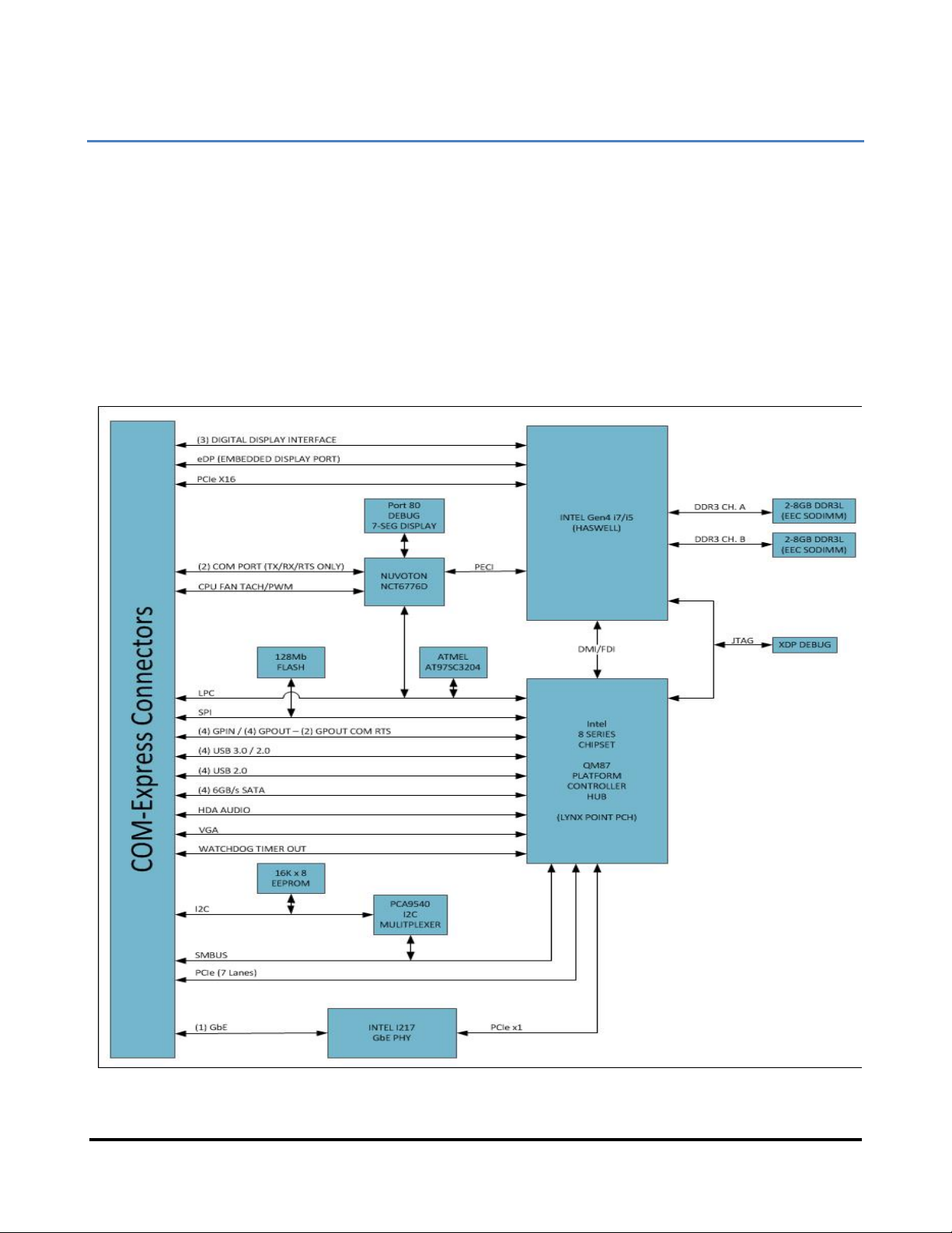
3.1.1XCOM-6400 COM Express CPU Module Block Diagram
ARCX 4000 SERIES
USER’S MANUAL
- 15 -
www.acromag.com
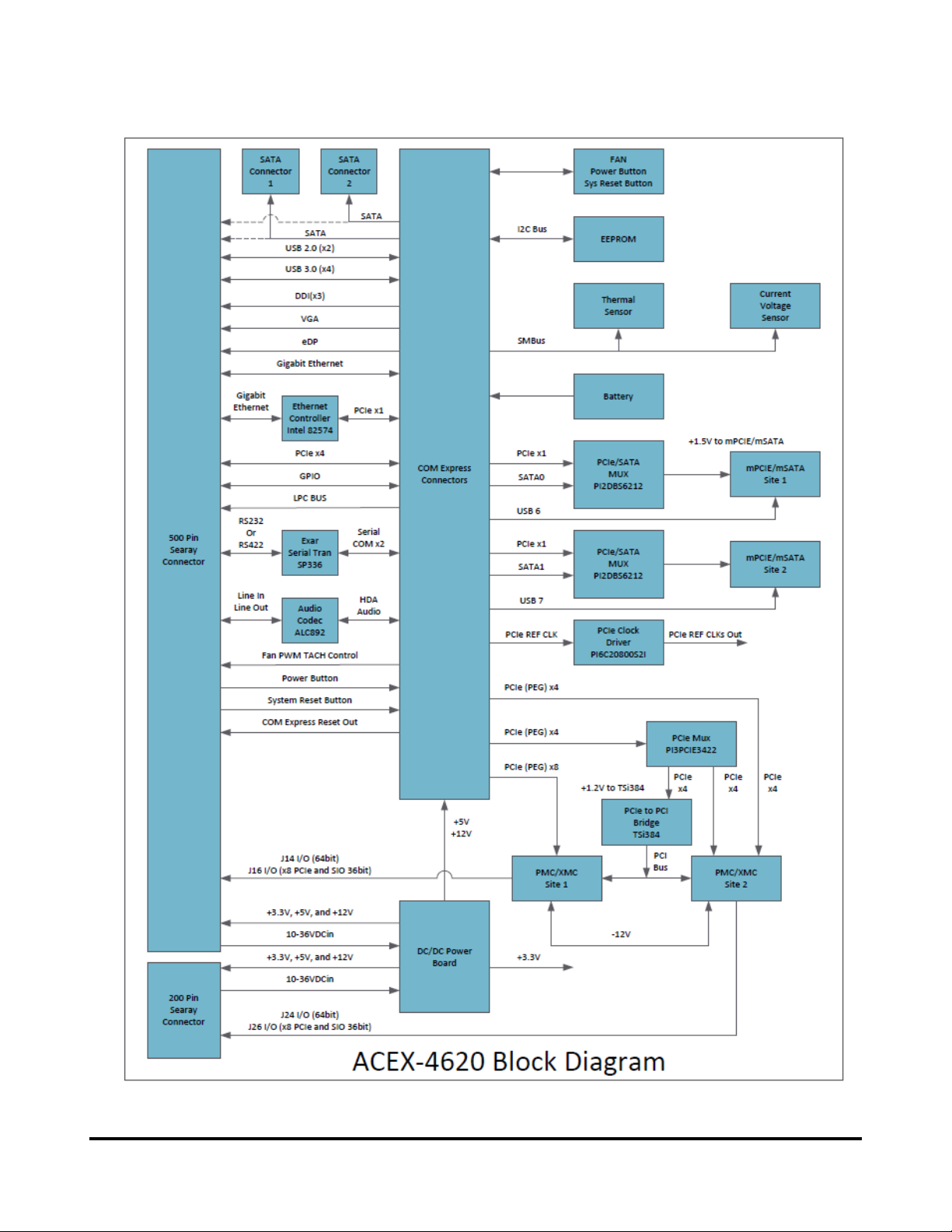
3.1.2 Model ACEX-4620 Carrier Block Diagram
ARCX 4000 SERIES
USER’S MANUAL
- 16 -
www.acromag.com
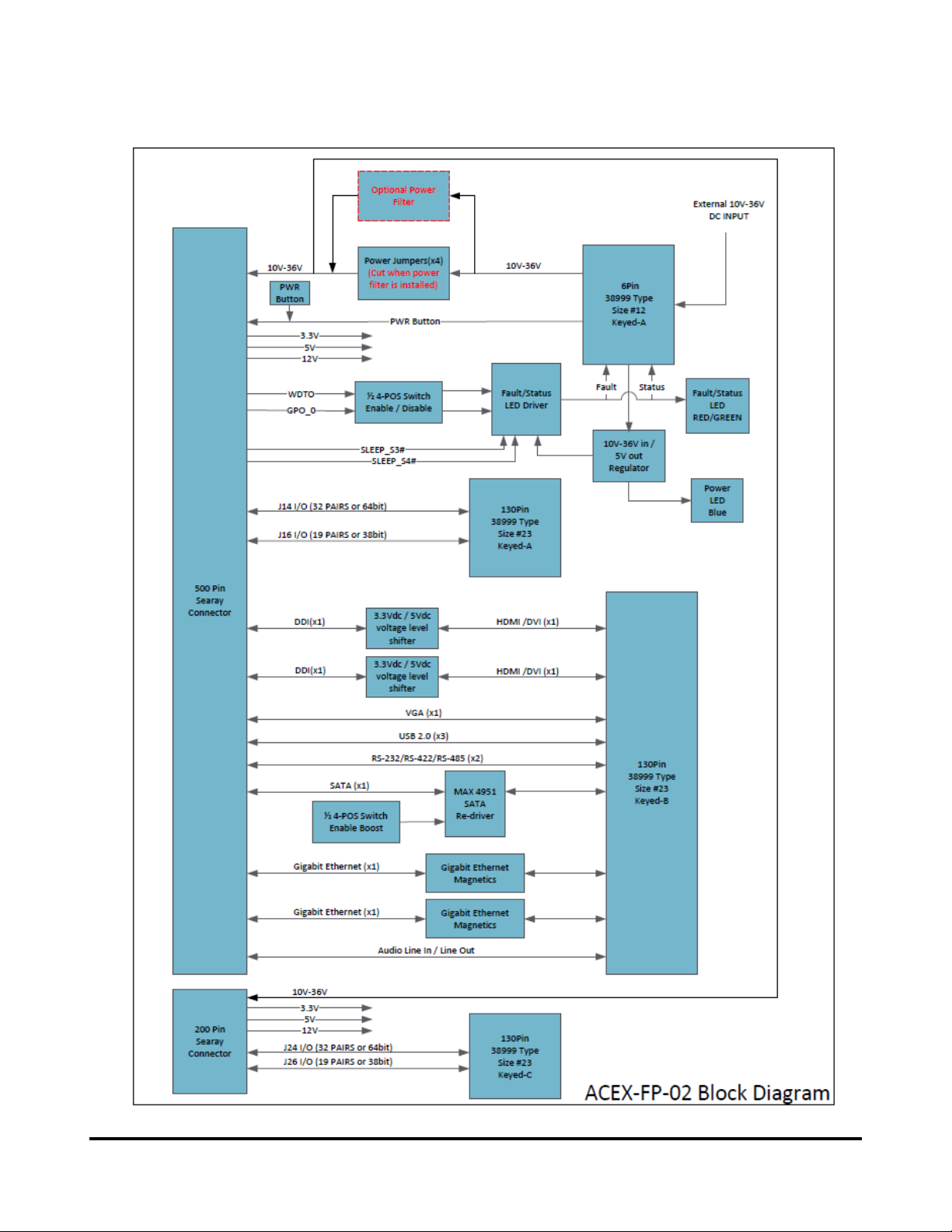
3.1.3Model ACEX-FP-02 Front Panel (standard) Block Diagram

ARCX 4000 SERIES
USER’S MANUAL
- 17 -
www.acromag.com
3.1.4 ARCX-4120, Top view
XMC / PMC
Expansion site 1
J2800
J2900
J16
J15
J13
J11
J14
J12
XMC / PMC
Expansion site 2
J26
J25
J23
J21
J24
J22
8 POS Dip Switch
mPCIe / mSATA
Site 1
Conduction RingConduction Ring
mPCIe / mSATA
Site 2
SATA 2
SATA 1
SATA Power
ACEX-4620 Carrier
Front Panel
(standard)
Front Panel (front view)
LED’s
XMC site 1 JTAG
Connector
ARCX 4000 SERIES
USER’S MANUAL
- 18 -
www.acromag.com
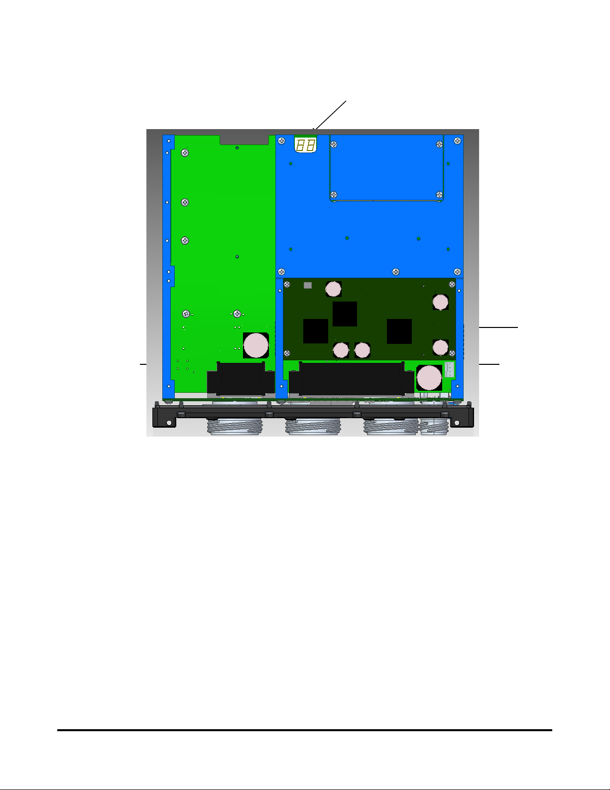
3.1.5 ARCX-4120, Bottom view
SODIMM
XCOM 6400 COM Express CPU
Internal Power supply
ACEX-PWR-xx
POST code diagnostics
200 - Pin SEARAY
Connector
500 - Pin SEARAY
Connector
This manual suits for next models
2
Table of contents
Popular Industrial PC manuals by other brands


Lenze
Lenze L-force MC Series Mounting instructions

GIGAIPC
GIGAIPC QBiX-Pro-EHLA6412H-A2 quick start guide

Beckhoff
Beckhoff C6525 Installation and operating instructions

ADLINK Technology
ADLINK Technology MXC-6000 user manual

IEI Technology
IEI Technology TANK-870AI SERIES user manual

Cincoze
Cincoze DE-1000 user manual


