EVOC P15 Series User manual

P15 SERIES
New generation 15-inch Industrial Panel PC
Version: C00
Legal Information
Warnings
Please pay attention to the tips within the manual so as to avoid personal injury or property
losses. The tips for personal injury are indicated in warning triangles while the tips only
related to property losses have no warning triangles. The warning tips are listed as follows
with the hazardous scale from severe to slight.
Danger
If handled carelessly, death or severe human injury will occur.
Warning
If handled carelessly, death or severe human injury might occur.
Caution
Warning triangle indicates that slight human injury might occur if handled carelessly.
Note
Unexpected result or status might occur, if not handled according to the tips.
Professional Personnel
The product/system covered by the manual can only be handled by qualified and
professional personnel. During operation, please follow the respective instructive manuals,
especially the safety warnings. The professional personnel have been trained and possess
relevant experiences; therefore, he/she could be aware of the risks of the product/system
and avoid possible damages.
EVOC Product
Please pay attention to the following instructions:
Warning
EVOC product can only be used according to the descriptions within the manual,
including the contents and the relevant technical documents. If the products or
components from other companies are required, please get the recommendation and grant
from EVOC first. Proper transportation, storage, assembly, installation, debugging,
operation and maintenance are prerequisite to ensure product safety and normal
operation; therefore, please ensure permitted environment conditions and pay attention to
the tips within the manual.

Copyright Notice
Information offered in this manual is believed to be correct at the time of printing, and is
subject to change without prior notice in order to improve reliability, design and function
and does not represent a commitment on the part of the manufacturer. In no event will the
manufacturer be liable for direct, indirect, special, incidental, or consequential damages
arising out of improper installation and/or use, or inability to use the product or
documentation.
This user manual is protected by copyright. No part of this manual may be reproduced,
stored in any retrieval system, or transmitted, in any form or by any means, mechanical,
electronic, photocopied, recorded or otherwise, without the prior written permission from
the manufacturer.
Trademarks
EVOC is a registered trademark of EVOC Intelligent Technology Co., Ltd. Other product
names mentioned herein are used for identification purposes only and may be trademark
and/or registered trademarks of their respective companies.
Warranty Terms:
The warranty on the product lasts for two years. If the user has additional requirements, the
contract signed between the two sides shall prevail.
Please visit our website: http://www.evoc.com for more information,
Hotline: 4008809666

About this manual
Scope of the Manual
The manual is appropriate for EVOC P15 SERIES.
Convention
The term “the PC” or “the Product” within the manual usually stands for EVOC P15
SERIES.
Instructions
Safety instructions
To avoid property losses or individual injury, please pay attention to the safety
instructions within the manual. The warnings within the manual are marked with
warning triangle , whose existence is dependent upon the scale of the potential
hazard.
History
The version of this manual:
Version Time
C00 2019.2
Safety Instructions
General Safety Instructions
Caution
Before you have read related safety instructions, please do not expand your device.
This device is compliant with related safety requirements. If you have any doubt about the
effectiveness of installation in the planned environment, please contact your service
representative.
Repair
The PC can only be repaired by authorized personnel.
Warning
Unauthorized opening of the PC and improper repair may cause serious damage to the
PC or endanger users’ personal safety.
System Expansion
Only system expansion devices designed for this PC can be installed. Installing other
expansion devices may damage the system and violate regulations on radio interference
suppression. To know the system expansion devices that can be installed, please contact
technical support team or local distributor.
Caution!
If the PC is damaged due to improper installation or replacement of system expansion
devices, the warranty for the product will become invalid.
'

ESD Instructions
The following label can be used to identify the modules that contain electrostatic sensitive
devices:
When operating the modules that contain electrostatic sensitive devices, please follow the
instructions below:
When operating the modules that contain electrostatic sensitive devices, make sure to
release static electricity on your body (for example, by touching a grounded object).
All the devices and tools should not contain ESD.
Before installing or removing modules that contain ESD, make sure to pull out the
power plug and remove the battery.
When assembling modules that contain ESD, always handle them by their edge.
Please do not touch any connector pin or conductive part on the modules that contain
ESD.

Contents
1. Product Introduction ..........................................................................................................1
1.1 Overview...................................................................................................................1
1.2 Specifications............................................................................................................2
1.3 Operating Instructions...............................................................................................6
1.3.1 External Functions ..........................................................................................6
1.3.2 Internal Layout................................................................................................8
1.3.3 Operation Control ...........................................................................................9
1.4 Status LED ................................................................................................................9
2. Application Scheme .........................................................................................................10
2.1 Transportation .........................................................................................................10
2.2 Storage ....................................................................................................................10
2.3 Opening the Box and Initial Examination...............................................................10
2.3.1 Opening the Box ...........................................................................................10
2.3.2 Markings for PC Identification .....................................................................11
2.4 External Environment Conditions...........................................................................11
3. Installing the Product .......................................................................................................12
3.1 Installation Information...........................................................................................12
3.2 Mounting Method ...................................................................................................12
3.2.1 Embedded Panel Installation.........................................................................12
3.2.2 VESA Standard Supporting Arm Installation ...............................................13
4. PC Connection .................................................................................................................14
4.1 Things to Know before Connection........................................................................14
4.2 Product Grounding..................................................................................................14
4.3 Connecting the Device to Power.............................................................................15
5. Debugging........................................................................................................................16
5.1 Operating System....................................................................................................16
5.2 Port Definition.........................................................................................................16
5.2.1 Power Input Connector .................................................................................16
5.2.2 USB Port .......................................................................................................16
5.2.3 PS/2 Keyboard/Mouse Port...........................................................................17

5.2.4 Network Port.................................................................................................17
5.2.5 HDMI Port ....................................................................................................18
5.2.6 VGA Port ......................................................................................................19
5.2.7 GPIO Port .....................................................................................................19
5.2.8 Standard DB9 COM Ports ............................................................................19
5.2.9 Display Port ..................................................................................................21
5.2.10 LCDB1 Backlight Control Port ..................................................................22
6. Software Introduction ......................................................................................................23
6.1 BPI Overview .........................................................................................................24
6.2 FMI Overview.........................................................................................................26
6.3 eManager Software .................................................................................................26
6.3.1 Operating Environment.................................................................................27
6.3.2 Function ........................................................................................................27
6.3.3 Firmware Management .................................................................................31
7. BIOS Setup ......................................................................................................................33
7.1 UEFI Overview.......................................................................................................33
7.2 UEFI Parameter Setup ............................................................................................33
7.3 Basic Function Setting............................................................................................34
7.3.1 Serial Function Setup....................................................................................34
8. Expansion Installation......................................................................................................36
8.1 Opening the PC.......................................................................................................36
8.2 HDD Expansion...................................................................................................... 37
8.3 Installing/Removing the MiniPCI-E.M-SATA ....................................................... 39
8.4 SIM Card Expansion...............................................................................................41
9. Technical Parameters .......................................................................................................44
9.1 Maximum Power Consumption of Accessory Assemblies.....................................44
10. Dimensions Drawing .....................................................................................................45
10.1 Dimensions Drawing Overview............................................................................45
10.2 Product Outline Dimensions Drawing..................................................................45
10.3 Installation Dimensions Drawing .........................................................................47
10.3.1 Product Installation Dimensions Drawing..................................................47

10.3.2 Recommended Dimensions Drawing for Hole Opening ............................49
10.3.3 The dimensions drawing of the product with mounting bracket ................50
11. PC Maintenance .............................................................................................................51
11.1 Removal/Installation of Hardware Assembly .......................................................51
11.1.1 Carry out Maintenance................................................................................51
11.1.2 Preventative Maintenance ...........................................................................51
11.1.3 Replacing Backup Battery...........................................................................52
11.2 Installing the Drivers.............................................................................................53
12. Appendix ........................................................................................................................54
12.1 Troubleshooting and Solutions .............................................................................54
12.2 Common Alarm Information Analysis and Solution.............................................55
12.3 ESD Guideline ......................................................................................................56
12.4 BIOS Setup ...........................................................................................................58
12.4.1 ECS-1837 UEFI Basic Function Setup.......................................................58
12.4.2 ECS-1838 Basic Function Setting for UEFI...............................................72
12.4.3 ECS-1840 Basic Function Setting for UEFI...............................................89
12.4.4 ECS-1841 Basic Function Setting for UEFI.............................................104
Product Introduction
P15 SERIES · 1 ·
1. Product Introduction
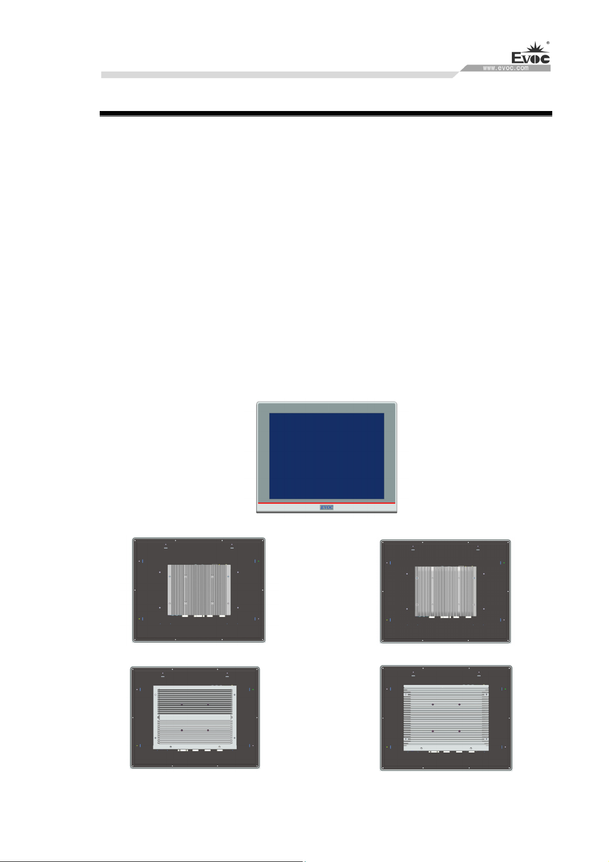
1.1 Overview
P15 family is a 15-inch industrial panel PC, and supports multiple platforms, for example:
Intel H110/C236, Intel Skylake-U SOC, Intel Bay Trail. It supports Windows 7(64bit),
Windows 10, LINUX (2.6 kernel) operating systems.
The PC is made of Al-alloy material. Its system structure deploys motherboard +
expansion board design solution, which features simplicity. Highly reliable connectors are
used among various modular boards, which ensures highly reliable operating environment.
The product has excellent anti-dust, heat-dissipation and anti-vibration performance.
Targeting high-end MES, integrated monitoring and equipment control and other fields,
P15 family products are mainly used in shield tunneling machines, production line MES,
integrated monitoring (rail transit, building and power plants, etc.), numerical control
machines, single crystal furnace machine, automobile accessories control, and so on.
With ECS-1837 With ECS-1838
With ECS-1840 With ECS-1841

Product Introduction
· 2 · P15 SERIES
1.2 Specifications
Item Definition
LCD screen
features
LCD screen:15″TFT LCD
Resolution:1024×768
Luminance:300cd/m2
Contrast:600:1
Viewable angle (CR≥10)
Horizontal:80°~80°; vertical:-70°~70°
Note: The parameters above are for reference only, and actual
product shall prevail if there is any difference.
Touchpad
Port type: USB
Type:5-wire resistive
Notes:(1) The touch screen can be used only after the driver has been
installed and calibrated.
(2)For touch screen calibration, For touch screen calibration, it is
recommended to use 16-dot or above advance mode in the advanced
positioning.(as shown below)
Temperature
Operating temperature:
With mechanical disks Operating:0℃~45℃
With SSD disks Operating:0℃~55℃
Storage temperature: -20℃~+60℃

Product Introduction
P15 SERIES · 3 ·
Humidity Temperature 40℃, Relative humidity 95% (non-condensing)
Expansion
bus
Provides two Mini PCIe sockets, Mini PCIe1 supports wifi or 4G
module, MSATA slot supports mSATA or 4G module
Network
Supports up to four 10/100/1000Mbps LAN ports. LAN1 supports
Wake-On-LAN
Audio HD standard, supporting MIC-IN/LINE-OUT
EMC
GB 9254-2008 Radio Disturbance Class(A)
GB 9254-2008 Conduction Emission Class(A)
GB/T 17626.2.2006 ESD Level(2)
GB/T 17626.4-2006 Burst Immunity Level(2)
GB/T 17626.5-2008 Surge(impact) immunity Level(2)
GB/T 17626.6-2008 Conduction Immunity Level(2)
Reliability
MTBF≥50000h
MTTR≤0.5h
Safety Meets basic requirements for GB4943-2011
Protection
grade Front panel meets IP65
Mechanical
and
environmental
adaptability
Power-off status anti-vibration: frequency 5-15Hz, amplitude
1mm; frequency 15-200Hz, acceleration 1.0g
Impact: 15g g acceleration, 11ms duration
Product Introduction
· 4 · P15 SERIES
Item Definition
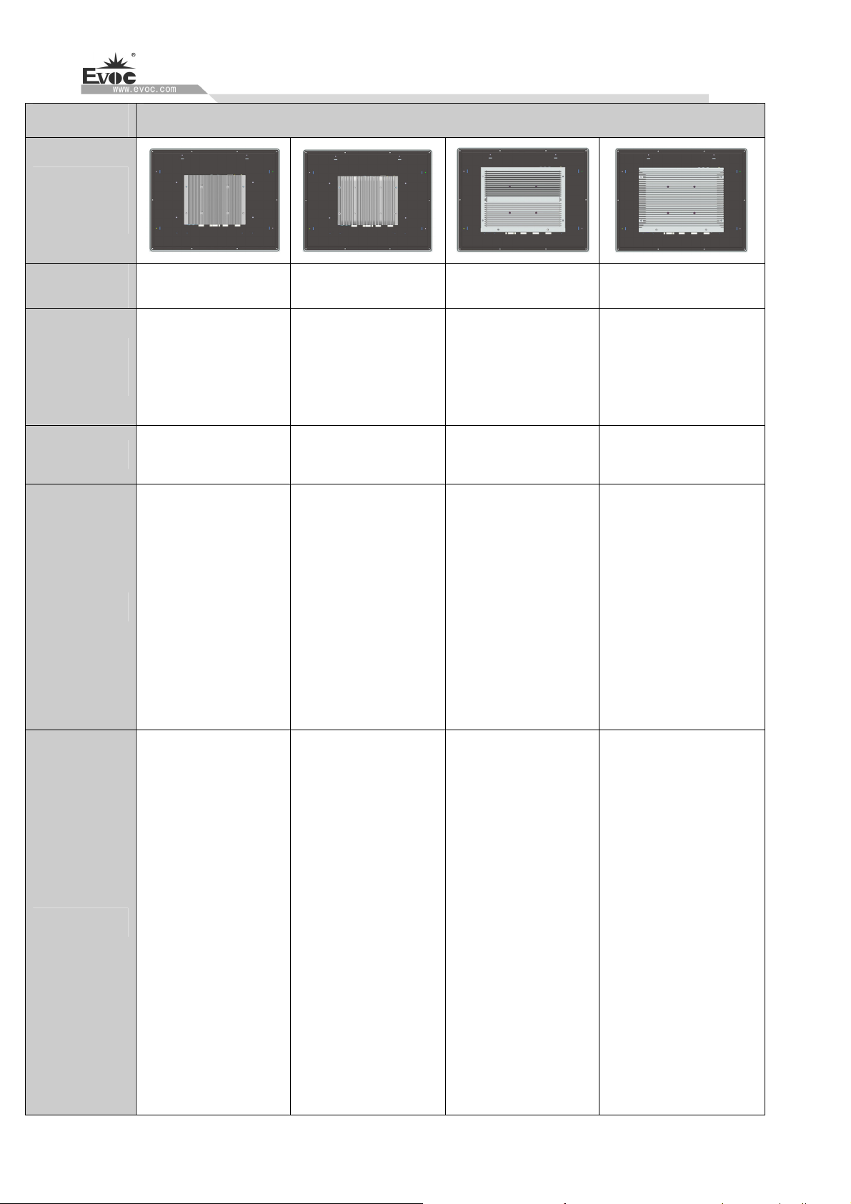
Product
Outline
With
motherboard ECS-1837 ECS-1838 ECS-1840 ECS-1841
Micropro-
cessor
Onboard Intel®
Celeron J1900 CPU
Onboard Intel®
I3-6100U/I5-6300U/I7
-6500U CPU
Onboard Intel®
Celeron J1900 CPU
Intel ® I3-6100TE/
I3-6300T/I5-6500TE/I5-65
00T/I5-6500/I7-6700TE
CPU
Chipset
Based on Intel® Bay
Trail platform
Based on Intel®
Skylake-U platform
Based on Intel® Bay
Trail platform
Based on Intel®
H110/C236 platform
Memory
1 x SO-DIMM
memory slot, 4G
DDR3L memory as
standard
configuration, which
supports up to 8G
memory
capacity (SO-DIMM),
and 8G DDR3L
memory needs
double-sided particles.
Onboard 4G DDR4
2133MHZ memory,1 x
260Pin DDR4
SO-DIMM memory
slot, which supports up
to 16GB. The PC
supports up to 20GB
memory capacity.
1 x SO-DIMM
memory slot, 4G
DDR3L memory as
standard
configuration, which
supports up to 8G
memory
capacity (SO-DIMM),
and 8G DDR3L
memory needs
double-sided particles.
2 x 260Pin DDR4
SO-DIMM memory
slot, , which supports up
to 16GB. The PC
supports up to 32GB
memory capacity.
Display
Supports external
display ports:
VGA, HDMI,
and dual-display
HDMI supports
up to 1920×1080
resolution.
VGA supports up
to 2560×1600
resolution.
Supports external
display ports:
VGA, HDMI, and
dual-display
HDMI supports
up to 2560×1600
resolution.
VGA supports up
to 2048×1536
resolution.
Supports external
display ports:
VGA, HDMI,
and dual-display
HDMI supports
up to 1920×1080
resolution.
VGA supports up
to 2560×1600
resolution.
Supports external
display ports:VGA,
HDMI, DVI and
dual-display,
triple-display(C236
platform)
HDMI supports up
to 2560×1600
resolution.
DVI supports up to
2560×1600
resolution.
VGA supports up
to 2048×1536
resolution.

Product Introduction
P15 SERIES · 5 ·
1 x PS/2 keyboard/mouse port
Supports up to four 10/100/1000Mbps LAN ports
1 x VGA port
1 x HDMI port
1 x 8-bit GPIO port (using 1x10 Phoenix terminal)
Up to four COM
ports, supporting
RS-232/RS-422/
RS-485 mode
selection, RS-232
by default
Up to: 1 x
USB3.0 port +5 x
USB2.0 ports
1 x AUDIO port
(supporting MIC,
LINE-OUT)
Up to four COM
ports, supporting
RS-232/RS-422/
RS-485 mode
selection, RS-232
by default
Up to: 2 x
USB3.0 ports +4
x USB2.0 ports
1 x AUDIO port
(supporting MIC,
LINE-OUT)
6 x COM ports,
supporting
RS-232/422/
485 mode
selection
Up to: 4 x
USB3.0 ports +4
x USB2.0 ports
1 x AUDIO port
(supporting MIC,
LINE-IN,
LINE-OUT)
6 x COM ports,
supporting
RS-232/422/485
mode selection
Up to: 1 x USB3.0
port +7 x USB2.0
ports
1 x AUDIO port
(supporting MIC,
LINE-IN,
LINE-OUT)
External
IO ports
Note: The quantity and type of the above ports may vary with different configurations. The actual
product shall prevail, if there is any difference.
1 x MSATA interface
Storage
1 x SATA interface, supporting hot swap 3 x SATA interfaces, supporting hot swap
374.5mm(W)× 298mm(H)
External
dimensions 78.5mm(D) 86.6mm(D) 81.2mm(D) 92.6mm(D)
Dimensions
for Hole Open 350.5mm(W)×274mm(H)
Weight
About: 4.25Kg
(excluding the weight
of package)
About:4.8Kg
(excluding the weight
of package)
About:5.5Kg
(excluding the weight
of package)
About:5.95Kg
(excluding the weight of
package)
Input voltage/frequency:220VAC/50Hz(with adapter)
Power Input Input voltage:DC-30VDC(no adapter, direct
input to the PC)
Input voltage:9VDC-36VDC(no adapter, direct
input to the PC)
Power
consumption
Power consumption of
the PC:
11.9W(standby status)
Power consumption of
the PC:
26.7W(operating TAT
100%)
Power consumption of
the PC:
21.1W(standby status)
Power consumption of
the PC:
30.9W(operating TAT
100%)
Power consumption of
the PC:
19.1W(standby status)
Power consumption of
the PC:
23.8W(operating TAT
100%)
Power consumption of
the PC:
16.4W(standby status)
Power consumption of
the PC:
52.6W(operating TAT
100%)
Product Introduction
· 6 · P15 SERIES
1.3 Operating Instructions
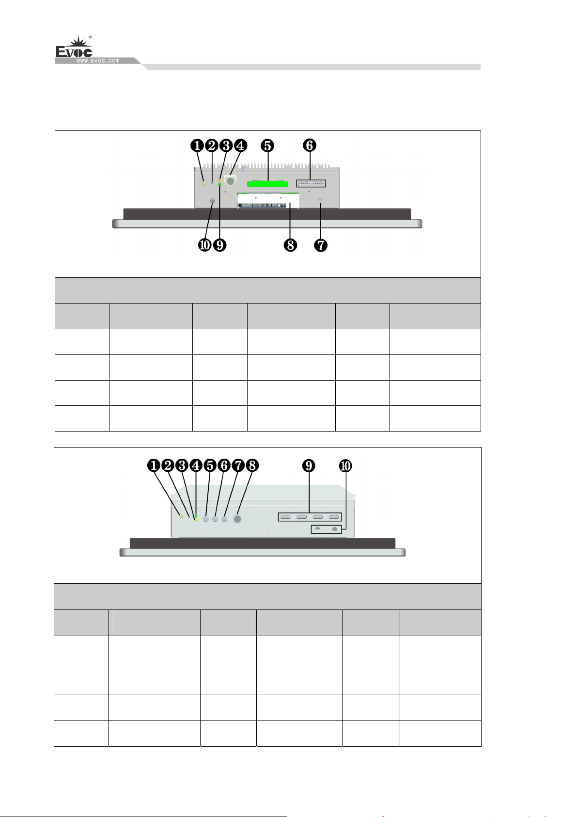
1.3.1 External Functions
With ECS-1837/ECS-1838
Diagram of upper IO ports of the PC
Location Description Location Description Location Description
1 On/Off button 2 Reset button 3 HDD indicator
4 PS/2 5 GPIO Port 6 USB1/2
7 ANT2 8 HDD bay 9 Power indicator
10 ANT1
With ECS-1840/ECS-1841
Diagram of upper IO ports of the PC
Location Description Location Description Location Description
1 On/Off button 2 Reset button 3 HDD indicator
4 Power indicator 5 LINE OUT 6 LINE IN
7 MIC 8 PS/2 9
USB1~4
10 ANT1/2
Product Introduction
P15 SERIES · 7 ·
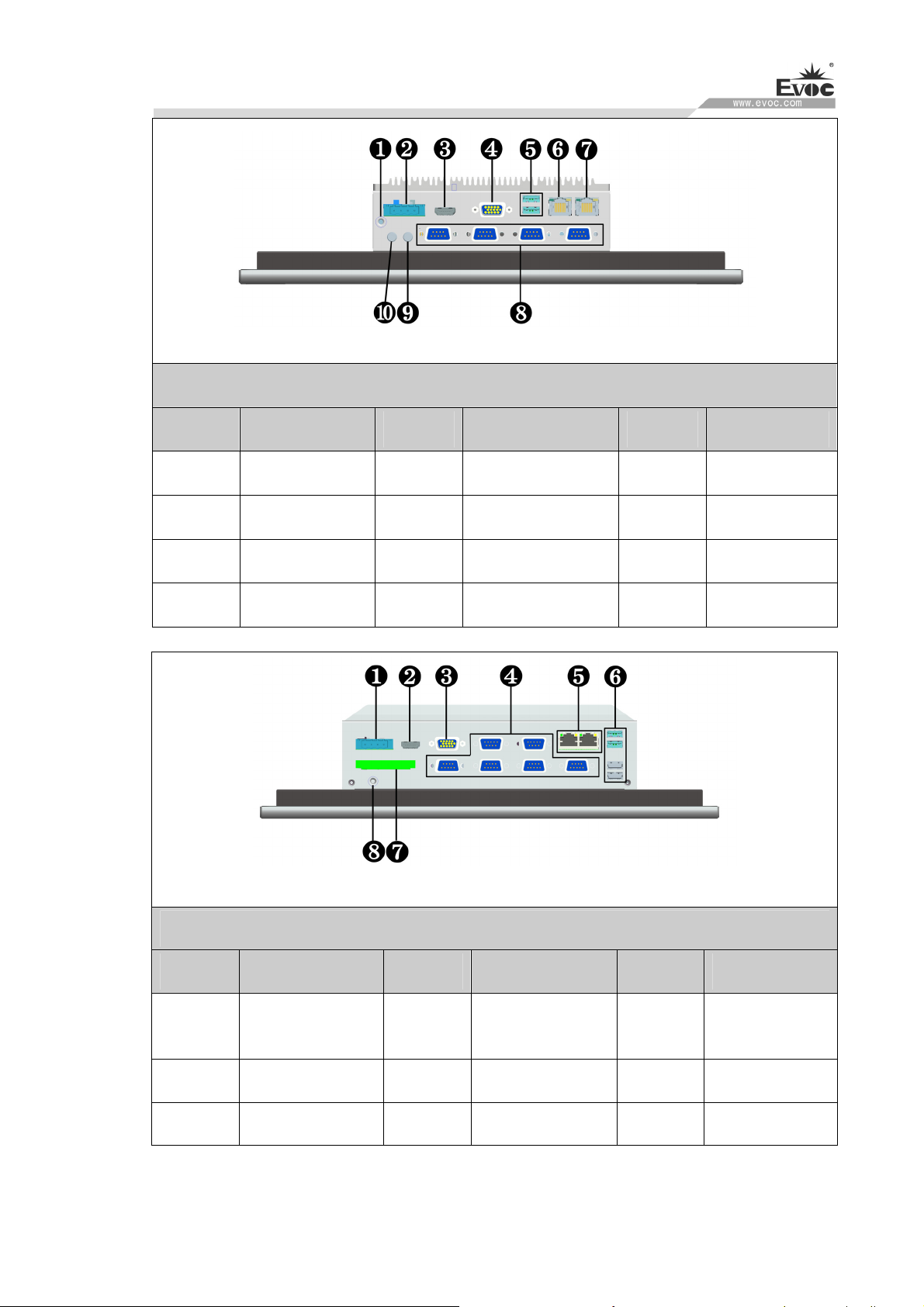
With ECS-1837/ECS-1838
Diagram of lower IO ports of the PC
Location Description Location Description Location Description
1 Ground screw 2 Power connector 3 HDMI
4 VGA 5 USB3/4 6 LAN1
7 LAN2 8
COM1~4 9 MIC IN
10 LINE OUT
With ECS-1840/ECS-1841
Diagram of lower IO ports of the PC
Location Description Location Description Location Description
1 Power connector 2 HDMI 3 VGA
4 COM1~6 5 LAN1/2 6
USB5~8
7 GPIO 8 Ground screw
Note:For different configurations of the PC (with different motherboards),the external IO
ports may be different,and the actual configuration prevails.
Product Introduction
· 8 · P15 SERIES
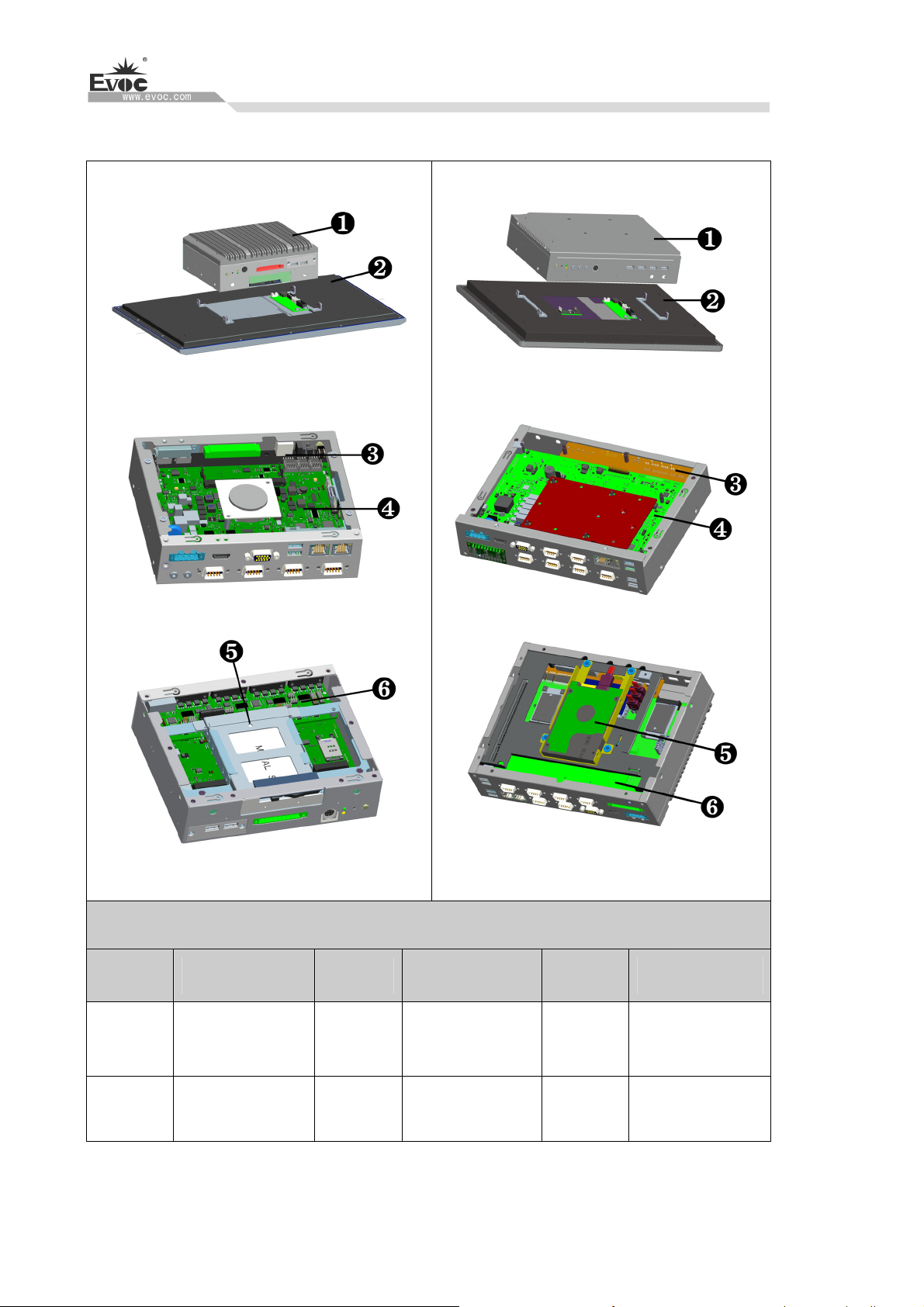
1.3.2 Internal Layout
(With ECS-1837/ECS-1838)
(With ECS-1840/ECS-1841)
Internal Layout of the PC
Location Description Location Description Location Description
1
Universal
quasi-system
2 P15 display part 3 Front IO board
4 Motherboard 5 HDD module 6 Rear IO board

Product Introduction
P15 SERIES · 9 ·
1.3.3 Operation Control
Warning
Pressing On/Off button won’t cut off the power of the PC!
Caution
When the PC executes hardware reset, data may be lost.
Control Button Location Description
1
On/Off button used to switch
on/off the PC.
2
Reset button
A pointed object or a clip
can be used to operate the
reset button. Pressing this
button will trigger hardware
1.4 Status LED
Display Meaning LED Description
Off Disconnected from power
Green PC is operating
POWER PC status indication
Orange Disable LCD screen
backlight and touch screen
Off Not being accessed
HDD
Indicating access to
hard drive Yellow Being accessed

Application Scheme
· 10 · P15 SERIES
2. Application Scheme
2.1 Transportation
Well-packaged products are suited for transportation by truck,ship,and plane.During
transportation,products should not be put in open cabin or carriage.During transshipping,
products should not be stored in open air without protection from the atmospheric
conditions.Products should not be transported together with inflammable,explosive and
corrosive substances and are not allowed to be exposed to rain,snow and liquid substances
and mechanical force.
2.2 Storage
Products should be stored in package box when it is not used. And warehouse temperature
should be 0°C ~ 40°C, and relative humidity should be 20% ~ 85%. In the warehouse,
there should be no harmful gas, inflammable, explosive products, and corrosive chemical
products, and strong mechanical vibration, shock and strong magnetic field interference.
The package box should be at least 10cm above ground, and 50cm away from wall,
thermal source, window and air inlet.
Caution!
Risk of destroying the device!
When shipping the PC in cold weather,please pay attention to the extreme
temperature variation.Under this circumstance,please make sure no water
drop(condensation) is formed on the surface or interior of the device.If
condensation is formed on the device,please wait for over twelve hours before
connecting the device.
2.3 Opening the Box and Initial Examination
2.3.1 Opening the Box
Please pay attention to the following issues when opening the box:
Do not discard the original packing material.Please keep the original packing material
for re-transportation.

Application Scheme
P15 SERIES · 11 ·
Please keep the documentation at a safe place.The documentation, which is a part of
the device,is required for initial device debugging.
When doing the initial examination,please check whether there are distinct damages to
the device caused during the transport.
Please check whether the delivery contains the intact device and all of the
independently ordered accessories.Please contact the customer service when any
unconformity or transportation damages occur.
2.3.2 Markings for PC Identification
Attention
When the product needs to be repaired or after it has been stolen, these codes can be used
to identify the PC. Please do not rip them off.
Serial number: located on the chassis body (as shown below)
2.4 External Environment Conditions
The following conditions should be considered when planning the project:
The weather and mechanical environment conditions specified in the operation manual
should be observed.
Please avoid extreme environment conditions. The PC should be protected against dust,
moisture and heat.
Please avoid direct exposure to sunlight.
Please make sure that other assemblies and side of cabinet are at least 50mm and
100mm away from the top and below the PC respectively.
Please do not block the ventilation hole of the PC.
The installation position requirement for the PC should be always observed.
The connected or installed I/O should not generate reverse voltage of more than 0.5V
inside the PC.
Table of contents
Other EVOC Industrial PC manuals

EVOC
EVOC ERC-1004A User manual

EVOC
EVOC MEC-4032 User manual

EVOC
EVOC LNB-1406 User manual

EVOC
EVOC PPC-1561 User manual

EVOC
EVOC IPC-820 User manual

EVOC
EVOC P12 Series User manual

EVOC
EVOC PPC-1781 Series User manual

EVOC
EVOC PPC-1006 User manual

EVOC
EVOC MEC-5031-M Series User manual

EVOC
EVOC P19 Series User manual


