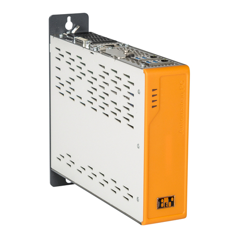
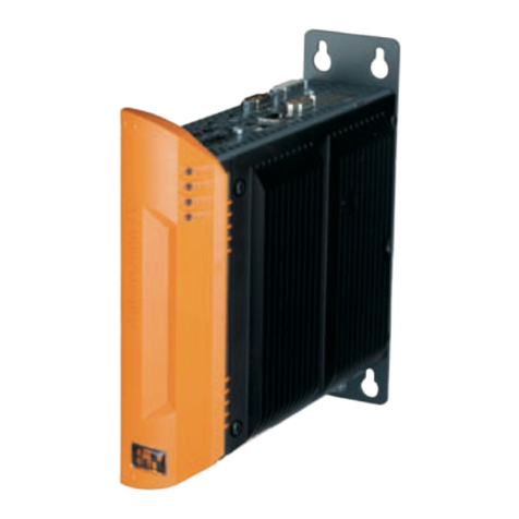
B&R Automation PC 910 User manual

1
Automation PC 910
User's Manual
Version: 1.00 (November 2012)
Model no.: MAAPC900-ENG
All information contained in this manual is current as of its creation/publication. We reserve the right to change
the contents of this manual without warning. The information contained herein is believed to be accurate
as of the date of publication; however, Bernecker + Rainer Industrie-Elektronik Ges.m.b.H. makes no war-
ranty, expressed or implied, with regard to the products or the documentation contained within this book.
Bernecker + Rainer Industrie-Elektronik Ges.m.b.H. shall not be liable in the event of incidental or consequential
damages in connection with or arising from the furnishing, performance or use of these products. The software
names, hardware names, and trademarks used in this document are registered by the respective companies.

Table of contents
Table of contents
Automation PC 910 User's Manual V 1.00 3
Chapter 1 General information................................................................................... 7
1 Manual history....................................................................................................................................................7
2 Safety guidelines.............................................................................................................................................. 8
2.1 Intended use............................................................................................................................................... 8
2.2 Protection against electrostatic discharge.................................................................................................. 8
2.2.1 Packaging.............................................................................................................................................. 8
2.2.2 Guidelines for proper ESD handling.......................................................................................................8
2.3 Policies and procedures..............................................................................................................................8
2.4 Transport and storage.................................................................................................................................9
2.5 Mounting......................................................................................................................................................9
2.6 Operation.....................................................................................................................................................9
2.6.1 Protection against touching electrical parts............................................................................................ 9
2.6.2 Environmental conditions - Dust, humidity, aggressive gases.............................................................. 9
2.6.3 Programs, viruses and dangerous programs......................................................................................... 9
2.7 Environmentally friendly............................................................................................................................ 10
2.7.1 Separation of materials........................................................................................................................10
3 Organization of safety notices......................................................................................................................... 11
4 Guidelines.........................................................................................................................................................11
5 Overview...........................................................................................................................................................12
Chapter 2 Technical data.......................................................................................... 14
1 Introduction.......................................................................................................................................................14
1.1 Intel® Core™ i-series processors for the most demanding tasks............................................................. 14
1.2 Maximum performance............................................................................................................................... 14
1.3 Availability and reliability for many productive years................................................................................. 14
1.4 Features......................................................................................................................................................15
1.5 System components / configuration........................................................................................................... 16
1.5.1 Configuration - Base system................................................................................................................ 16
1.5.2 Configuration - Accessories and software............................................................................................ 18
2 Complete device............................................................................................................................................. 19
2.1 Temperature specifications.........................................................................................................................19
2.1.1 Maximum ambient temperature............................................................................................................ 20
2.1.2 Minimum ambient temperature............................................................................................................. 21
2.1.3 Temperature monitoring........................................................................................................................22
2.1.4 Temperature sensor locations.............................................................................................................. 22
2.2 Humidity specifications............................................................................................................................... 23
2.3 Power management................................................................................................................................... 24
2.3.1 Block diagram - Supply voltage............................................................................................................24
2.3.2 Power calculation with 5PC910.SX01-00............................................................................................. 25
2.3.3 Power calculation with 5PC910.SX02-00............................................................................................. 26
2.4 Block diagram.............................................................................................................................................27
2.4.1 System unit 5PC910.SX01-00 + bus unit 5AC901.BX01-00................................................................ 27
2.4.2 System unit 5PC910.SX01-00 + bus unit 5AC901.BX01-01................................................................ 28
2.4.3 System unit 5PC910.SX02-00 + bus unit 5AC901.BX02-00................................................................ 29
2.4.4 System unit 5PC910.SX02-00 + bus unit 5AC901.BX02-01................................................................ 30
2.4.5 Monitor / panel options......................................................................................................................... 31
2.5 Device interfaces.......................................................................................................................................32
2.5.1 Overview of device interfaces...............................................................................................................32
2.5.2 Supply voltage +24 VDC...................................................................................................................... 34
2.5.3 Serial interface COM1......................................................................................................................... 35
2.5.4 Monitor / panel connection................................................................................................................... 36
2.5.5 DisplayPort............................................................................................................................................ 37
2.5.6 Ethernet 1 (ETH1).................................................................................................................................38
2.5.7 Ethernet 2 (ETH2).................................................................................................................................38
2.5.8 USB ports..............................................................................................................................................39
2.5.9 IF option 1 slot......................................................................................................................................40
2.5.10 IF option 2 slot....................................................................................................................................40

Table of contents
4 Automation PC 910 User's Manual V 1.00
2.5.11 Card slot (PCI / PCIe).........................................................................................................................41
2.5.12 Status LEDs........................................................................................................................................ 42
2.5.13 Power button....................................................................................................................................... 43
2.5.14 Reset button........................................................................................................................................43
2.5.15 Battery................................................................................................................................................. 44
2.5.16 CFast slot............................................................................................................................................ 44
2.5.17 Slide-in compact slot...........................................................................................................................45
3 Individual components..................................................................................................................................... 46
3.1 System units............................................................................................................................................... 46
3.1.1 5PC910.SX01-00...................................................................................................................................46
3.1.2 5PC910.SX02-00...................................................................................................................................51
3.2 QM77 CPU boards..................................................................................................................................... 56
3.2.1 5PC900.TS77-0x...................................................................................................................................56
3.3 HM76 CPU boards..................................................................................................................................... 58
3.3.1 5PC900.TS77-0x...................................................................................................................................58
3.4 Main memory............................................................................................................................................ 60
3.4.1 5MMDDR.xxxx-03................................................................................................................................. 60
3.5 Bus units................................................................................................................................................... 61
3.5.1 5AC901.BX0x-0x...................................................................................................................................61
3.6 Heat sink.....................................................................................................................................................62
3.6.1 5AC901.HS0x-00...................................................................................................................................62
3.7 Fan kit.........................................................................................................................................................63
3.7.1 5AC901.FA01-00................................................................................................................................... 63
3.7.2 5AC901.FA02-00................................................................................................................................... 64
3.8 Drives..........................................................................................................................................................65
3.8.1 5AC901.CHDD-00.................................................................................................................................65
3.8.2 5AC901.CSSD-00................................................................................................................................. 67
3.8.3 5AC901.CSSD-01................................................................................................................................. 69
3.8.4 5AC901.CSSD-02................................................................................................................................. 71
3.8.5 5AC901.CCFA-00..................................................................................................................................73
3.9 Interface options......................................................................................................................................... 74
3.9.1 5AC901.I485-00.................................................................................................................................... 74
3.9.2 5AC901.ICAN-00...................................................................................................................................78
3.9.3 5AC901.IHDA-00...................................................................................................................................80
3.9.4 5AC901.ISRM-00.................................................................................................................................. 82
3.10 Monitor / panel options.............................................................................................................................83
3.10.1 5AC901.LDPO-00................................................................................................................................83
3.10.2 5AC901.LSDL-00................................................................................................................................ 85
3.11 Front covers.............................................................................................................................................. 87
3.11.1 5AC901.FF0x-00................................................................................................................................. 87
Chapter 3 Commissioning.........................................................................................88
1 Mounting...........................................................................................................................................................88
1.1 Important mounting information..................................................................................................................88
1.2 Procedure................................................................................................................................................... 88
1.3 Mounting orientation................................................................................................................................... 89
1.3.1 Mounting orientation - Vertical..............................................................................................................89
1.3.2 Mounting orientation - Horizontal..........................................................................................................89
1.4 Spacing for air circulation...........................................................................................................................90
2 Cable connections............................................................................................................................................91
3 Grounding concept...........................................................................................................................................92
Chapter 4 Software.................................................................................................... 93
1 Windows 7........................................................................................................................................................93
1.1 General information.................................................................................................................................... 93
1.2 Order data.................................................................................................................................................. 93
1.3 Overview..................................................................................................................................................... 93

Table of contents
Table of contents
Automation PC 910 User's Manual V 1.00 5
1.4 Installation...................................................................................................................................................94
1.5 Drivers.........................................................................................................................................................94
1.6 Special considerations, limitations............................................................................................................. 94
2 Windows Embedded Standard 7..................................................................................................................... 95
2.1 General information.................................................................................................................................... 95
2.2 Order data.................................................................................................................................................. 95
2.3 Overview..................................................................................................................................................... 95
2.4 Features with WES7 (Windows Embedded Standard 7)........................................................................... 96
2.5 Installation...................................................................................................................................................96
2.6 Drivers.........................................................................................................................................................96
2.6.1 Touch screen driver.............................................................................................................................. 96
3 Windows XP Professional................................................................................................................................97
3.1 Order data.................................................................................................................................................. 97
3.2 Overview..................................................................................................................................................... 97
3.3 Installation...................................................................................................................................................97
3.4 Drivers.........................................................................................................................................................97
4 Windows Embedded Standard 2009............................................................................................................... 98
4.1 General information.................................................................................................................................... 98
4.2 Order data.................................................................................................................................................. 98
4.3 Overview..................................................................................................................................................... 98
4.4 Features with WES2009 (Windows Embedded Standard 2009)............................................................... 98
4.5 Installation...................................................................................................................................................99
4.6 Drivers.........................................................................................................................................................99
5 B&R Automation Device Interface (ADI) - Control Center........................................................................... 100
5.1 Functions.................................................................................................................................................. 100
5.2 Installation.................................................................................................................................................101
6 B&R Automation Device Interface (ADI) Development Kit............................................................................ 102
7 B&R Automation Device Interface (ADI) .NET SDK......................................................................................104
Chapter 5 Accessories........................................................................................... 106
1 Power connectors.......................................................................................................................................... 106
1.1 0TB103.9x.................................................................................................................................................106
1.1.1 General information.............................................................................................................................106
1.1.2 Order data........................................................................................................................................... 106
1.1.3 Technical data.....................................................................................................................................106
2 Replacement CMOS batteries....................................................................................................................... 107
2.1 0AC201.91 / 4A0006.00-000....................................................................................................................107
2.1.1 General information.............................................................................................................................107
2.1.2 Order data........................................................................................................................................... 107
2.1.3 Technical data.....................................................................................................................................107
3 CFast cards....................................................................................................................................................108
3.1 5CFAST.xxxx-00....................................................................................................................................... 108
3.1.1 General information.............................................................................................................................108
3.1.2 Order data........................................................................................................................................... 108
3.1.3 Technical data.....................................................................................................................................108
3.1.4 Dimensions..........................................................................................................................................109
3.1.5 Temperature humidity diagram........................................................................................................... 110
4 USB flash drive.............................................................................................................................................111
4.1 5MMUSB.2048-01.................................................................................................................................... 111
4.1.1 General information.............................................................................................................................111
4.1.2 Order data........................................................................................................................................... 111
4.1.3 Technical data.....................................................................................................................................111
4.1.4 Temperature humidity diagram........................................................................................................... 112
5 USB Media Drive..........................................................................................................................................113
5.1 5MD900.USB2-02.....................................................................................................................................113
5.1.1 General information.............................................................................................................................113
5.1.2 Order data........................................................................................................................................... 113

Table of contents
6 Automation PC 910 User's Manual V 1.00
5.1.3 Interfaces.............................................................................................................................................113
5.1.4 Technical data.....................................................................................................................................113
5.1.5 Dimensions..........................................................................................................................................115
5.1.6 Dimensions with front cover............................................................................................................... 115
5.1.7 Cutout installation................................................................................................................................116
5.1.8 Contents of delivery............................................................................................................................ 116
5.1.9 Installation........................................................................................................................................... 116
5.2 5A5003.03.................................................................................................................................................117
5.2.1 General information.............................................................................................................................117
5.2.2 Order data........................................................................................................................................... 117
5.2.3 Technical data.....................................................................................................................................117
5.2.4 Dimensions..........................................................................................................................................117
5.2.5 Contents of delivery............................................................................................................................ 117
5.2.6 Installation........................................................................................................................................... 117
6 Cables...........................................................................................................................................................119
6.1 DVI cables...............................................................................................................................................119
6.1.1 5CADVI.0xxx-00..................................................................................................................................119
6.2 SDL cables..............................................................................................................................................122
6.2.1 5CASDL.0xxx-00.................................................................................................................................122
6.3 SDL cables with 45° plugs......................................................................................................................125
6.3.1 5CASDL.0xxx-01.................................................................................................................................125
6.4 SDL flex cables.......................................................................................................................................128
6.4.1 5CASDL.0xxx-03.................................................................................................................................128
6.5 SDL flex cables with extender................................................................................................................ 131
6.5.1 5CASDL.0xx0-13.................................................................................................................................131
6.6 USB cables............................................................................................................................................. 135
6.6.1 5CAUSB.00xx-00................................................................................................................................ 135
6.7 RS232 cables..........................................................................................................................................136
6.7.1 9A0014.xx.......................................................................................................................................... 136
Chapter 6 Maintenance / Service............................................................................138
1 Replacing a CFast card.................................................................................................................................138
2 Installation - Interface option......................................................................................................................... 139
3 Installation - Monitor / panel option............................................................................................................... 143
4 Slide-in compact drive installation / replacement.......................................................................................... 147
5 Slide-in drive installation / replacement.........................................................................................................149
6 Fan filter replacement.................................................................................................................................... 151
7 Fan kit replacement....................................................................................................................................... 152
Appendix A .............................................................................................................. 154
1 Abbreviations..................................................................................................................................................154

General information • Manual history
Chapter 1
General information
Automation PC 910 User's Manual V 1.00 7
Chapter 1 • General information
1 Manual history
Version Date Change
0.10 Preliminary 12-Jun-12 •First version
1.00 26-Nov-12 •Chapter "Software" on page 93 added.
•Chapter "Maintenance / Service" on page 138 added.
•"Appendix A" on page 154 was added.
•Section "Organization of safety notices" on page 11 revised - description text for "Caution" and "Warn-
ing" rewritten.
•Terminology changes in German edition.
•The following sections were added to the chapter "Technical data": "Temperature specifications" on page
19, "Block diagram" on page 27, "Humidity specifications" on page 23.
•The following sections were added to the chapter "Commissioning": "Mounting orientation" on page 89,
"Spacing for air circulation" on page 90, "Grounding concept" on page 92.
•The CPU boards 5PC900.TS77-00, 5PC900.TS77-01, 5PC900.TS77-05, 5PC900.TS77-06,
5PC900.TS77-07 and 5PC900.TS77-08 were added to the chapter "QM77 CPU boards" on page 56
and "HM76 CPU boards" on page 58.
•The following drives were added: "5AC901.CSSD-00" on page 67, "5AC901.CSSD-01" on page 69,
"5AC901.CSSD-02" on page 71, "5AC901.CCFA-00" on page 73.
•The following interface options were added: "5AC901.ICAN-00" on page 78, "5AC901.IHDA-00" on
page 80, "5AC901.ISRM-00" on page 82.
•Section "Monitor / panel options" on page 83 added.
•The heat sink 5AC901.HS01-00 was added, "5AC901.HS0x-00" on page 62.
•The section "System components / configuration" on page 16 was changed.
•The bus units 5AC901.BX01-01 and 5AC901.BX02-01 were updated, see " Bus units" on page 61.
•"CFast cards" on page 108 added.
•USB Media Drive "5MD900.USB2-02" on page 113 added.

General information • Safety guidelines
8 Automation PC 910 User's Manual V 1.00
2 Safety guidelines
2.1 Intended use
Programmable logic controllers (PLCs), operating/monitoring devices (industrial PCs, Power Panels, Mobile Pan-
els, etc.), and B&R uninterruptible power supplies have been designed, developed, and manufactured for conven-
tional use in industrial environments. They were not designed, developed and manufactured for any use involving
serious risks or hazards that could lead to death, injury, serious physical damage or loss of any kind without the
implementation of exceptionally stringent safety precautions. In particular, such risks and hazards include the use
of these devices to monitor nuclear reactions in nuclear power plants, their use in flight control or flight safety sys-
tems as well as in the control of mass transportation systems, medical life support systems or weapons systems.
2.2 Protection against electrostatic discharge
Electrical components that can be damaged by electrostatic discharge (ESD) must be handled accordingly.
2.2.1 Packaging
•Electrical components with a housing
… do not require special ESD packaging but must be handled properly (see Section "Electrical components
with housing").
•Electrical components without a housing
… must be protected by ESD-suitable packaging.
2.2.2 Guidelines for proper ESD handling
Electrical components with a housing
•Do not touch the connector contacts on connected cables.
•Do not touch the contact tips on circuit boards.
Electrical components without a housing
The following apply in addition to "Electrical components with housing":
•Any persons handling electrical components or devices with electrical components installed in them must
be grounded.
•Components may only be touched on their narrow sides or front plate.
•Components should always be stored in a suitable medium (ESD packaging, conductive foam, etc.). Metal-
lic surfaces are not suitable storage surfaces!
•Components should not be subjected to electrostatic discharge (e.g. through the use of charged plastics).
•Ensure a minimum distance of 10 cm from monitors and TV sets.
•Measurement devices and equipment must be grounded.
•Measurement probes on potential-free measurement devices must be discharged on sufficiently grounded
surfaces before taking measurements.
Individual components
•ESD protective measures for individual components are thoroughly integrated at B&R (conductive floors,
footwear, arm bands, etc.).
•These increased ESD protective measures for individual components are not necessary for customers
handling B&R products.
2.3 Policies and procedures
Electronic devices are never completely failsafe. In the event of a failure on the programmable control system,
operating/monitoring device or uninterruptible power supply, the user is responsible for ensuring that other devices
that may be connected, e.g. motors, are brought to a safe state.

General information • Safety guidelines
Chapter 1
General information
Automation PC 910 User's Manual V 1.00 9
When using programmable logic controllers or operating/monitoring devices as control systems in conjunction with
a Soft PLC (e.g. B&R Automation Runtime or comparable product) or slot PLC (e.g. B&R LS251 or comparable
product), the safety precautions applying to industrial control systems (e.g. the provision of safety devices such
as emergency stop circuits, etc.) must be observed in accordance with applicable national and international regu-
lations. The same applies for all other devices connected to the system, such as drives.
All tasks such as installation, commissioning and maintenance are only permitted to be carried out by qualified
personnel. Qualified personnel are those familiar with the transport, mounting, installation, commissioning and
operation of the device who also have the appropriate qualifications (e.g. IEC 60364). National accident prevention
regulations must be observed.
The safety notices, connection descriptions (type plate and documentation) and limit values listed in the technical
data are to be read carefully before installation and commissioning and must be observed.
2.4 Transport and storage
During transport and storage, devices must be protected against undue stress (mechanical loads, temperature,
humidity, aggressive atmospheres, etc.).
2.5 Mounting
•Installation must be performed according to this documentation using suitable equipment and tools.
•Devices may only be installed by qualified personnel without voltage applied. Before installation, voltage
to the control cabinet must be switched off and prevented from being switched on again.
•General safety guidelines and national accident prevention regulations must be observed.
•Electrical installation must be carried out according to applicable guidelines (e.g. line cross-section, fuses,
protective ground connections).
2.6 Operation
2.6.1 Protection against touching electrical parts
To operate programmable logic controllers, operating/monitoring devices or uninterruptible power supplies, certain
components must carry dangerous voltage levels of over 42 VDC. Touching one of these parts can result in a life-
threatening electric shock. This could lead to death, severe injury or damage to equipment.
Before turning on the programmable logic controller, operating/monitoring devices and the uninterruptible power
supply, the housing must be properly grounded (PE rail). Ground connections must be established when testing
operating/monitoring devices or the uninterruptible power supply even when operating them for only a short time!
Before turning the device on, all parts that carry voltage must be securely covered. During operation, all covers
must remain closed.
2.6.2 Environmental conditions - Dust, humidity, aggressive gases
The use of operating/monitoring devices (e.g. industrial PCs, Power Panels, Mobile Panels, etc.) and uninterruptible
power supplies in very dusty environments should be avoided. Dust collection on the devices can affect functionality
and may prevent sufficient cooling, especially in systems with active cooling systems (fans).
The presence of aggressive gases can also lead to malfunctions. When combined with high temperature and
humidity, aggressive gases – e.g. with sulfur, nitrogen and chlorine components – can induce chemical reactions
that can damage electronic components very quickly. Signs of the presence of aggressive gases are blackened
copper surfaces and cable ends on existing equipment.
For operation in dusty or humid conditions, correctly installed (cutout installation) operating/monitoring devices like
the Automation Panel or Power Panel are protected on the front side. The rear side of all devices must be protected
from dust and humidity and cleaned at suitable intervals.
2.6.3 Programs, viruses and dangerous programs
This system is subject to potential risk each time data is exchanged or software is installed from a data medium
(e.g. diskette, CD-ROM, USB flash drive, etc.), a network connection or the Internet. The user is responsible for
assessing these dangers, implementing preventive measures such as virus protection programs, firewalls, etc. and
making sure that software is only obtained from trusted sources.

General information • Safety guidelines
10 Automation PC 910 User's Manual V 1.00
2.7 Environmentally friendly
All B&R programmable controllers, operating/monitoring devices and uninterruptible power supplies are designed
to inflict as little harm as possible on the environment.
2.7.1 Separation of materials
It is necessary to separate different materials so the device can undergo an environmentally friendly recycling
process.
Component Disposal
Programmable logic controllers
Operating/monitoring devices
Uninterruptible power supply
Batteries & rechargeable batteries
Cables
Electronics recycling
Cardboard box / paper packaging Paper / cardboard recycling
Plastic packaging Plastic recycling
Table 1: Environmentally friendly separation of materials
Disposal must comply with applicable legal regulations.

General information • Guidelines
Chapter 1
General information
Automation PC 910 User's Manual V 1.00 11
3 Organization of safety notices
The safety notices in this manual are organized as follows:
Safety notice Description
Danger! Disregarding safety regulations and notices can be life-threatening.
Warning! Disregarding safety regulations and notices can result in severe injury or substantial damage to equipment.
Caution! Disregarding safety guidelines and notices can result in injury or damage to equipment.
Information: Important information for preventing errors.
Table 2: Description of the safety notices used in this documentation
4 Guidelines
E
European dimension standards apply to all dimension diagrams in this document.
All dimensions are specified in mm.
Nominal measurement area General tolerance according to
DIN ISO 2768 medium
Up to 6 mm ±0.1 mm
For 6 to 30 mm ±0.2 mm
For 30 to 120 mm ±0.3 mm
For 120 to 400 mm ±0.5 mm
For 400 to 1000 mm ±0.8 mm
Table 3: Nominal measurement areas

General information • Overview
12 Automation PC 910 User's Manual V 1.00
5 Overview
Product ID Short description on page
Batteries
0AC201.91 Lithium batteries 4 pieces, 3 V / 950 mAh button cell Hereby we declare that the Lithium cells contained in this
shipment qualify as „partly regulated“. Handle with care. If the package is damaged, inspect cells, repack intact
cells and protect cells against short circuits. For emergency information, call RENATA SA at + 41 61 319 28 27
107
4A0006.00-000 Lithium battery, 3 V / 950 mAh, button cell 107
Bus units
5AC901.BX01-00 APC910 bus, 1 PCI 61
5AC901.BX01-01 APC910 bus, 1 PCI Express (x4) 61
5AC901.BX02-00 APC910 bus, 2 PCI 61
5AC901.BX02-01 APC910 bus, 1 PCI, 1 PCI Express (x8) 61
CFast cards
5CFAST.016G-00 CFast 16 GB 108
5CFAST.032G-00 CFast 32 GB 108
5CFAST.2048-00 CFast 2 GB 108
5CFAST.4096-00 CFast 4 GB 108
5CFAST.8192-00 CFast 8 GB 108
CPU boards
5PC900.TS77-00 Intel Core i7 3615QE CPU board, 2.3 GHz, quad-core, 6 MB L2 cache; QM77 chipset; 2 sockets for SO-DIMM
DDR3 modules (total memory max. 16 GB)
56
5PC900.TS77-01 Intel Core i7 3612QE CPU board, 2.1 GHz, quad-core, 6 MB L2 cache; QM77 chipset; 2 sockets for SO-DIMM
DDR3 modules (total memory max. 16 GB)
56
5PC900.TS77-02 Intel Core i7 3555LE CPU board, 2.5 GHz, dual-core, 4 MB L2 cache; QM77 chipset; 2 sockets for SO-DIMM
DDR3 modules (max. total memory 16 GB)
56
5PC900.TS77-03 Intel Core i7 3517UE CPU board, 1.7 GHz, dual-core, 4 MB L2 cache; QM77 chipset; 2 sockets for SO-DIMM
DDR3 modules (max. total memory 16 GB)
56
5PC900.TS77-04 Intel Core i5 3610ME CPU board, 2.7 GHz, dual-core, 3 MB L2 cache; QM77 chipset; 2 sockets for SO-DIMM
DDR3 modules (max. total memory 16 GB)
56
5PC900.TS77-05 Intel Core i3 3120ME CPU board, 2.4 GHz, dual-core, 3 MB L2 cache; QM77 chipset; 2 sockets for SO-DIMM
DDR3 modules (total memory max. 16 GB)
56
5PC900.TS77-06 Intel Core i3 3217UE CPU board, 1.6 GHz, dual-core, 3 MB L2 cache; QM77 chipset; 2 sockets for SO-DIMM
DDR3 modules (total memory max. 16 GB)
56
5PC900.TS77-07 Intel Celeron M 847E CPU board, 1.1 GHz, dual-core, 1 MB L2 cache; HM76 chipset; 2 sockets for SO-DIMM
DDR3 modules (total memory max. 16 GB)
58
5PC900.TS77-08 Intel Celeron M 827E CPU board, 1.4 GHz, single-core, 1.5 MB L2 cache; HM76 chipset; 2 sockets for SO-
DIMM DDR3 modules (total memory max. 16 GB)
58
DVI cable
5CADVI.0018-00 DVI-D cable, 1.8 m. 119
5CADVI.0050-00 DVI-D cable, 5 m. 119
5CADVI.0100-00 DVI-D cable, 10 m. 119
Drives
5AC901.CCFA-00 CFast adapter to operate a CFast card in a slide-in compact slot 73
5AC901.CHDD-00 250 GB SATA hard disk, Slide-in compact, 24/7 hard disk 65
5AC901.CSSD-00 32 GB SATA SSD (SLC), Slide-in compact 67
5AC901.CSSD-01 60 GB SATA SSD (MLC), Slide-in compact 69
5AC901.CSSD-02 180 GB SATA SSD (MLC), Slide-in compact 71
Fan kits
5AC901.FA01-00 APC910 fan kit for system unit 5PC910.SX01-00 63
5AC901.FA02-00 APC910 fan kit for system unit 5PC910.SX02-00 64
Front cover
5AC901.FF01-00 APC910 front cover, 1 slot, orange 87
5AC901.FF02-00 APC910 front cover 2 slot, orange 87
Heat sink
5AC901.HS00-00 APC910 heat sink active 62
5AC901.HS01-00 APC910 heat sink passive 62
Interface options
5AC901.I485-00 RS232/422/485 interface option; for APC910 74
5AC901.ICAN-00 CAN interface option; for APC910 78
5AC901.IHDA-00 Audio interface option, connection for 1x MIC, 1x Line IN, 1x Line OUT; for APC910 80
5AC901.ISRM-00 SRAM interface option, 2 MB; for APC910 82
Main memory
5MMDDR.1024-03 SO-DIMM DDR3, 1024 MB 60
5MMDDR.2048-03 SO-DIMM DDR3, 2048 MB 60
5MMDDR.4096-03 SO-DIMM DDR3, 4096 MB 60
5MMDDR.8192-03 SO-DIMM DDR3, 8192 MB 60
Monitor / Panel options
5AC901.LDPO-00 DisplayPort transmitter 83
5AC901.LSDL-00 Smart Display Link/DVI transmitter 85
RS232 cable
9A0014.02 RS232 extension cable for remote operating of a display unit with touch screen, 1.8 m. 136
9A0014.05 RS232 extension cable for remote operating of a display unit with touch screen, 5 m. 136
9A0014.10 RS232 extension cable for remote operating of a display unit with touch screen, 10 m. 136
SDL cable - 45° connector
5CASDL.0018-01 SDL cable; 45° connector, 1.8 m. 125

General information • Overview
Chapter 1
General information
Automation PC 910 User's Manual V 1.00 13
Product ID Short description on page
5CASDL.0050-01 SDL cable; 45° connector, 5 m. 125
5CASDL.0100-01 SDL cable; 45° connector, 10 m. 125
5CASDL.0150-01 SDL cable; 45° connector, 15 m. 125
SDL cables
5CASDL.0018-00 SDL cable, 1.8 m. 122
5CASDL.0050-00 SDL cable, 5 m. 122
5CASDL.0100-00 SDL cable, 10 m. 122
5CASDL.0150-00 SDL cable, 15 m. 122
5CASDL.0200-00 SDL cable, 20 m. 122
5CASDL.0250-00 SDL cable, 25 m. 122
5CASDL.0300-00 SDL cable, 30 m. 122
SDL flex cable
5CASDL.0018-03 SDL Cable flex, 1.8 m. 128
5CASDL.0050-03 SDL cable flex, 5 m. 128
5CASDL.0100-03 SDL cable flex, 10 m. 128
5CASDL.0150-03 SDL cable flex, 15 m. 128
5CASDL.0200-03 SDL cable flex, 20 m. 128
5CASDL.0250-03 SDL cable flex, 25 m. 128
5CASDL.0300-03 SDL cable flex, 30 m. 128
5CASDL.0300-13 SDL cable flex with extender, 30 m. 131
5CASDL.0400-13 SDL cable flex with extender, 40 m. 131
5CASDL.0430-13 SDL Cable flex with extender, 43 m. 131
System units
5PC910.SX01-00 APC910 system unit, 1 slot (PCI Express / PCI, depending on bus), 1 slide-in compact slot; Smart Display Link/
DVI/monitor, DisplayPort, 1x RS232, 5x USB, 2x ETH 10/100/1000, 1 CFast slot, 24 VDC
46
5PC910.SX02-00 APC910 system unit, 2 slots (PCI Express / PCI, depending on bus), 1 slot for monitor/panel option, 1 slide-
in compact and 1 slide-in slot; Smart Display Link/DVI/Monitor, DisplayPort, 1x RS232, 5x USB, 2x ETH
10/100/1000, 1 CFast slot, 24 VDC
51
Terminal blocks
0TB103.9 Connector, 24 VDC, 3-pin female, screw clamps 3.31 mm², protected against vibration by the screw flange 106
0TB103.91 Connector, 24 VDC, 3-pin female, cage clamps 3.31 mm², protected against vibration by the screw flange 106
USB accessories
5A5003.03 Front cover, For Remote CD-ROM Drive 5A5003.02 and USB 2.0 drive combination 5MD900.USB2-00,
5MD900.USB2-01 and 5MD900.USB2-02.
117
5MD900.USB2-02 USB 2.0 Drives DVD-R/RW DVD+R/RW, CompactFlash slot (type II), USB connector (type A on front side, type
B on back side); 24 VDC; (0TB103.9 screw clamp or 0TB103.91 cage clamp must be ordered separately).
113
5MMUSB.2048-01 USB 2.0 flash drive 2048 MB B&R 111
USB cable
5CAUSB.0018-00 USB 2.0 connecting cable type A - type B, 1.8 m. 135
5CAUSB.0050-00 USB 2.0 connecting cable type A - type B, 5 m. 135
Windows 7
5SWWI7.1100-ENG Microsoft OEM Windows 7 Professional 32-bit, Service Pack 1, DVD, English. Only available with a new device. 93
5SWWI7.1100-GER Microsoft OEM Windows 7 Professional 32-bit, Service Pack 1, DVD, German. Only available with a new device. 93
5SWWI7.1200-ENG Microsoft OEM Windows 7 Professional 64-bit, Service Pack 1, DVD, English. Only available with a new device. 93
5SWWI7.1200-GER Microsoft OEM Windows 7 Professional 64-bit, Service Pack 1, DVD, German. Only available with a new device. 93
5SWWI7.1300-MUL Microsoft OEM Windows 7 Ultimate 32-bit, Service Pack 1, DVD, multilanguage. Only available with a new
device.
93
5SWWI7.1400-MUL Microsoft OEM Windows 7 Ultimate 64-bit, Service Pack 1, DVD, multilanguage. Only available with a new
device.
93
Windows Embedded Standard 2009
5SWWXP.0740-ENG Microsoft OEM Windows Embedded Standard 2009, English; for APC910 with QM77/HM76 chipset; please
order CFast separately (minimum 2 GB).
98
Windows Embedded Standard 7
5SWWI7.1540-ENG Microsoft OEM Windows Embedded Standard 7 32-bit, Service Pack 1, English; for APC910 with QM77/HM76
chipset; please order CFast separately (minimum 16 GB).
95
5SWWI7.1640-ENG Microsoft OEM Windows Embedded Standard 7 64-bit, Service Pack 1, English; for APC910 with QM77/HM76
chipset; please order CFast separately (minimum 16 GB).
95
5SWWI7.1740-MUL Microsoft OEM Windows Embedded Standard 7 Premium 32-bit, Service Pack 1, multilanguage; for APC910
with QM77/HM76 chipset; please order CFast separately (minimum 16 GB without language packages).
95
5SWWI7.1840-MUL Microsoft OEM Windows Embedded Standard 7 Premium 64-bit, Service Pack 1, multilanguage; for APC910
with QM77/HM76 chipset; please order CFast separately (minimum 16 GB).
95
Windows XP Professional
5SWWXP.0600-ENG Microsoft OEM Windows XP Professional Service Pack 3, CD, English. Only available with a B&R device. 97
5SWWXP.0600-GER Microsoft OEM Windows XP Professional Service Pack 3, CD, German. Only available with a device. 97
5SWWXP.0600-MUL Microsoft OEM Windows XP Professional Service Pack 3, CD, multilanguage. Only available with a B&R device. 97

Technical data • Introduction
14 Automation PC 910 User's Manual V 1.00
Chapter 2 • Technical data
1 Introduction
1.1 Intel® Core™ i-series processors for the most demanding tasks
The APC910 is based on the latest Intel® Core™ i-series technology and offers maximum performance for de-
manding tasks such as those that involve vision systems. The proven standard design of the Automation PCs has
been retained while adding many new details to keep up with the advancements being made on the PC market.
Robust design for use in industrial applications around the world and long-term series availability continue to define
the Automation PC series, a trend now being continued by the APC910.
1.2 Maximum performance
The APC910 has the latest Intel® Core™ i-series technology at its heart. By further reducing the structural size
of the chip and implementing a new microprocessor architecture that now integrates graphics directly into the
CPU, Intel® has been able to improve performance by leaps and bounds over their first Core™ i-series generation
and Core™2 Duo systems. The rest of the PC infrastructure has also been streamlined for maximum computing
performance and optimal data throughput. The APC910 now has a serial ATA-based CFast card to replace the
previously used CompactFlash. And just like the APC810, hard disks and solid state drives are connected to the
PC system via the high-speed SATA interface. These devices are also well-equipped when it comes to interface
options. Two gigabit Ethernet ports, USB ports and onboard as well as modular serial ports round off the extensive
capabilities of the ACP910.
1.3 Availability and reliability for many productive years
Automation PCs are built for continuous operation over a period of many years. This starts with the robust welded
housing that shields the electronics from the external environment, easily withstanding rough conditions. The in-
dustrial-grade paint can endure even the most aggressive environments so that even a well-seasoned Automation
PC might be mistaken for new. Components have also been selected to provide many years of reliable service.
These components have been designed specifically for use in industrial environments, can withstand high ambient
temperatures and have guaranteed long-term availability. In addition, Automation PC generations are produced
in excess of 10 years – quite the exception in the otherwise fast-paced PC sector and a significant advantage for
the user. The third generation of Automation PCs, represented by the APC910, proves once again that innovation

Technical data • Introduction
Chapter 2
Technical data
Automation PC 910 User's Manual V 1.00 15
and product continuity are not incompatible goals. From the ease of connecting cables to the ports on top of the
device to the location of mounting holes, many details have stayed the same. For the many thousands of panels
in the field – whether customized or in the standard design – there is always the proven SDL interface for easily
connecting the PC to its display.
1.4 Features
•Latest processor technology - Intel® Core™ i-series (Generation 3 - Ivy Bridge)
•Up to 16 GB main memory (dual-channel memory support)
•1 CFast slot1)
•1 or 2 card slots (for PCI / PCI Express (PCIe) cards)
•SATA drives (slide-in and slide-in compact slots)
•4x USB 3.0, 1x USB 2.0
•2x Ethernet 10/100/1000 Mbit interfaces
•1x RS232 interface, modem compatible
•Connections for a wide range of display devices to the monitor/panel interface and display port
•24 VDC supply voltage
•Fan-free operation2)
•BIOS (AMI)
•Real-time clock (RTC, battery-backed)
•Wide range of interface options
•Wide range of monitor/panel options
1) A CFast adapter allows multiple CFast cards to be used. This depends on the respective system unit.
2) Dependent on the device configuration and ambient temperature

Technical data • Introduction
16 Automation PC 910 User's Manual V 1.00
1.5 System components / configuration
The APC910 system can be assembled to meet individual requirements and operating conditions. The following
components are absolutely essential for operation:
•System unit
•Bus unit
•CPU board
•Heat sink
•Fan kit3)
•Main memory
•Drive (mass storage device such as CFast card or hard disk) for the operating system
•Software
1.5.1 Configuration - Base system
The system units can be operated with and without a fan kit. This depends on the various types of heat sink and
main memory being used.
Using a fan kit allows for operation at higher ambient temperatures. More information can be found under "Maximum
ambient temperature" on page 20.
Configuration with a fan kit
C
P
U
b
o
a
r
d
S
e
l
e
c
t
o
n
e
S
e
l
e
c
t
o
n
e
S
y
s
t
e
m
u
n
i
t
C
o
n
f
i
g
u
r
a
t
i
o
n
-
B
a
s
e
s
y
s
t
e
m
(
w
i
t
h
f
a
n
k
i
t
-
a
c
t
i
v
e
)
C
P
U
b
o
a
r
d
-
H
e
a
t
s
i
n
k
-
F
a
n
k
i
t
-
M
a
i
n
m
e
m
o
r
y
S
e
l
e
c
t
o
n
e
H
e
a
t
s
i
n
k
A
s
y
s
t
e
m
u
n
i
t
c
o
n
s
i
s
t
s
o
f
a
h
o
u
s
i
n
g
a
n
d
m
a
i
n
b
o
a
r
d
.
5
A
C
9
0
1
.
H
S
0
0
-
0
0
5
P
C
9
1
0
.
S
X
0
1
-
0
0
B
u
s
u
n
i
t
S
e
l
e
c
t
o
n
e
5
A
C
9
0
1
.
B
X
0
1
-
0
0
-
1
P
C
I
5
A
C
9
0
1
.
B
X
0
1
-
0
1
-
1
P
C
I
e
S
e
l
e
c
t
o
n
e
o
r
t
w
o
M
a
i
n
m
e
m
o
r
y
5
P
C
9
1
0
.
S
X
0
2
-
0
0
5
A
C
9
0
1
.
B
X
0
2
-
0
0
-
2
P
C
I
5
A
C
9
0
1
.
B
X
0
2
-
0
1
-
1
P
C
I
,
1
P
C
I
e
5
M
M
D
D
R
.
1
0
2
4
-
0
3
5
M
M
D
D
R
.
2
0
4
8
-
0
3
5
M
M
D
D
R
.
4
0
9
6
-
0
3
5
M
M
D
D
R
.
8
1
9
2
-
0
3
F
a
n
k
i
t
S
e
l
e
c
t
o
n
e
5
A
C
9
0
1
.
F
A
0
1
-
0
0
5
A
C
9
0
1
.
F
A
0
2
-
0
0
5
P
C
9
0
0
.
T
S
7
7
-
0
0
5
P
C
9
0
0
.
T
S
7
7
-
0
1
5
P
C
9
0
0
.
T
S
7
7
-
0
2
5
P
C
9
0
0
.
T
S
7
7
-
0
3
5
P
C
9
0
0
.
T
S
7
7
-
0
7
5
P
C
9
0
0
.
T
S
7
7
-
0
8
5
P
C
9
0
0
.
T
S
7
7
-
0
4
5
P
C
9
0
0
.
T
S
7
7
-
0
5
5
P
C
9
0
0
.
T
S
7
7
-
0
6
Q
M
7
7
C
P
U
b
o
a
r
d
s
H
M
7
6
C
P
U
b
o
a
r
d
s
Figure 1: Configuration - Base system with fan kit
3) A fan kit is only mandatory when using the heat sink 5AC901.HS00-00.

Technical data • Introduction
Chapter 2
Technical data
Automation PC 910 User's Manual V 1.00 17
Configuration without a fan kit
C
P
U
b
o
a
r
d
S
e
l
e
c
t
o
n
e
S
e
l
e
c
t
o
n
e
S
y
s
t
e
m
u
n
i
t
C
o
n
f
i
g
u
r
a
t
i
o
n
-
B
a
s
e
s
y
s
t
e
m
(
w
i
t
h
o
u
t
f
a
n
k
i
t
-
p
a
s
s
i
v
e
)
C
P
U
b
o
a
r
d
-
H
e
a
t
s
i
n
k
-
M
a
i
n
m
e
m
o
r
y
S
e
l
e
c
t
o
n
e
H
e
a
t
s
i
n
k
A
s
y
s
t
e
m
u
n
i
t
c
o
n
s
i
s
t
s
o
f
a
h
o
u
s
i
n
g
a
n
d
m
a
i
n
b
o
a
r
d
.
5
A
C
9
0
1
.
H
S
0
1
-
0
0
5
P
C
9
1
0
.
S
X
0
1
-
0
0
B
u
s
u
n
i
t
S
e
l
e
c
t
o
n
e
5
A
C
9
0
1
.
B
X
0
1
-
0
0
-
1
P
C
I
5
A
C
9
0
1
.
B
X
0
1
-
0
1
-
1
P
C
I
e
S
e
l
e
c
t
o
n
e
o
r
t
w
o
M
a
i
n
m
e
m
o
r
y
5
P
C
9
1
0
.
S
X
0
2
-
0
0
5
A
C
9
0
1
.
B
X
0
2
-
0
0
-
2
P
C
I
5
A
C
9
0
1
.
B
X
0
2
-
0
1
-
1
P
C
I
,
1
P
C
I
e
5
P
C
9
0
0
.
T
S
7
7
-
0
7
5
P
C
9
0
0
.
T
S
7
7
-
0
8
5
P
C
9
0
0
.
T
S
7
7
-
0
4
5
P
C
9
0
0
.
T
S
7
7
-
0
5
5
P
C
9
0
0
.
T
S
7
7
-
0
6
5
P
C
9
0
0
.
T
S
7
7
-
0
2
5
P
C
9
0
0
.
T
S
7
7
-
0
3
5
P
C
9
0
0
.
T
S
7
7
-
0
1
Q
M
7
7
C
P
U
b
o
a
r
d
s
H
M
7
6
C
P
U
b
o
a
r
d
s
5
M
M
D
D
R
.
1
0
2
4
-
0
3
5
M
M
D
D
R
.
2
0
4
8
-
0
3
5
M
M
D
D
R
.
4
0
9
6
-
0
3
5
M
M
D
D
R
.
8
1
9
2
-
0
3
Figure 2: Configuration - Base system without fan kit

Technical data • Introduction
18 Automation PC 910 User's Manual V 1.00
1.5.2 Configuration - Accessories and software
F
r
o
n
t
c
o
v
e
r
S
e
l
e
c
t
o
n
e
S
y
s
t
e
m
u
n
i
t
S
e
l
e
c
t
o
n
e
M
o
n
i
t
o
r
/
P
a
n
e
l
o
p
t
i
o
n
s
O
p
e
r
a
t
i
n
g
s
y
s
t
e
m
s
S
e
l
e
c
t
o
n
e
5
S
W
W
I
7
.
1
1
0
0
-
E
N
G
5
S
W
W
I
7
.
1
1
0
0
-
G
E
R
5
S
W
W
I
7
.
1
3
0
0
-
M
U
L
5
S
W
W
I
7
.
1
2
0
0
-
E
N
G
5
S
W
W
I
7
.
1
2
0
0
-
G
E
R
5
S
W
W
I
7
.
1
4
0
0
-
M
U
L
W
i
n
d
o
w
s
7
W
i
n
d
o
w
s
X
P
5
S
W
W
X
P
.
0
6
0
0
-
E
N
G
5
S
W
W
X
P
.
0
6
0
0
-
G
E
R
5
S
W
W
X
P
.
0
6
0
0
-
M
U
L
W
i
n
d
o
w
s
E
m
b
e
d
d
e
d
S
t
a
n
d
a
r
d
7
5
S
W
W
I
7
.
1
5
4
0
-
E
N
G
5
S
W
W
I
7
.
1
6
4
0
-
E
N
G
5
S
W
W
I
7
.
1
7
4
0
-
M
U
L
5
S
W
W
I
7
.
1
8
4
0
-
M
U
L
W
i
n
d
o
w
s
E
m
b
e
d
d
e
d
S
t
a
n
d
a
r
d
2
0
0
9
5
S
W
W
X
P
.
0
7
4
0
-
E
N
G
A
u
t
o
m
a
t
i
o
n
R
u
n
t
i
m
e
1
A
4
6
0
0
.
1
0
-
5
1
A
4
6
0
1
.
0
6
-
5
I
F
o
p
t
i
o
n
s
S
e
l
e
c
t
m
a
x
.
2
C
o
n
f
i
g
u
r
a
t
i
o
n
-
A
c
c
e
s
s
o
r
i
e
s
a
n
d
s
o
f
t
w
a
r
e
S
e
l
e
c
t
o
n
e
T
e
r
m
i
n
a
l
b
l
o
c
k
s
0
T
B
1
0
3
.
9
0
T
B
1
0
3
.
9
1
P
o
w
e
r
c
o
n
n
e
c
t
o
r
s
A
s
y
s
t
e
m
u
n
i
t
c
o
n
s
i
s
t
s
o
f
a
h
o
u
s
i
n
g
a
n
d
m
a
i
n
b
o
a
r
d
.
5
P
C
9
1
0
.
S
X
0
1
-
0
0
5
P
C
9
1
0
.
S
X
0
2
-
0
0
5
A
C
9
0
1
.
F
F
0
1
-
0
0
5
A
C
9
0
1
.
F
F
0
2
-
0
0
5
A
C
9
0
1
.
I
4
8
5
-
0
0
5
A
C
9
0
1
.
I
C
A
N
-
0
0
C
o
m
p
a
c
t
s
l
i
d
e
-
i
n
d
r
i
v
e
S
e
l
e
c
t
o
n
e
5
A
C
9
0
1
.
C
H
D
D
-
0
0
5
A
C
9
0
1
.
C
S
S
D
-
0
0
5
A
C
9
0
1
.
C
S
S
D
-
0
1
5
A
C
9
0
1
.
L
D
P
O
-
0
0
5
A
C
9
0
1
.
L
S
D
L
-
0
0
S
e
l
e
c
t
o
n
e
U
S
B
a
c
c
e
s
s
o
r
i
e
s
5
M
M
U
S
B
.
2
0
4
8
-
0
1
S
e
l
e
c
t
o
n
e
5
A
C
9
0
1
.
I
H
D
A
-
0
0
5
A
C
9
0
1
.
I
S
R
M
-
0
0
1
)
C
e
r
t
a
i
n
l
i
m
i
t
a
t
i
o
n
s
m
u
s
t
b
e
t
a
k
e
n
i
n
t
o
a
c
c
o
u
n
t
w
h
e
n
u
s
i
n
g
I
F
o
p
t
i
o
n
s
.
F
o
r
m
o
r
e
i
n
f
o
r
m
a
t
i
o
n
,
p
l
e
a
s
e
r
e
f
e
r
t
o
"
C
h
a
p
t
e
r
2
T
e
c
h
n
i
c
a
l
d
a
t
a
"
,
s
e
c
t
i
o
n
"
D
e
v
i
c
e
i
n
t
e
r
f
a
c
e
s
"
.
5
A
C
9
0
1
.
C
S
S
D
-
0
2
5
A
C
9
0
1
.
C
C
F
A
-
0
0
1
)
S
e
l
e
c
t
o
n
e
C
F
a
s
t
c
a
r
d
s
5
C
F
A
S
T
.
2
0
4
8
-
0
0
5
C
F
A
S
T
.
4
0
9
6
-
0
0
5
C
F
A
S
T
.
8
1
9
2
-
0
0
5
C
F
A
S
T
.
0
1
6
G
-
0
0
5
C
F
A
S
T
.
0
3
2
G
-
0
0
Figure 3: Configuration - Accessories and software

Technical data • Complete device
Chapter 2
Technical data
Automation PC 910 User's Manual V 1.00 19
2 Complete device
2.1 Temperature specifications
CPU boards can be combined with various other components, such as drives, main memory, additional insert
cards, etc. depending on the system unit and fan kit. The various configurations result in varying maximum possible
ambient temperatures, which can be seen in the following tables.
Information:
The maximum specified ambient temperatures for operation with and without a fan kit were determined
under worst-case conditions. Experience has shown that higher ambient temperatures can be reached
under typical conditions, e.g. using Microsoft Windows. The testing and evaluation is to be done on-
site by the user (temperatures can be read in BIOS or using the B&R Control Center).
Information regarding worst-case conditions
•Thermal Analysis Tool (TAT V4.3) from Intel for simulating a 100% processor load
•BurnInTest tool (BurnInTest V4.0 Pro from Passmark Software) for simulating a 100% load on the interface
via loop back adapters (serial interfaces, slide-in drives, USB ports, audio outputs)
•Maximum system expansion and power consumption

Technical data • Complete device
20 Automation PC 910 User's Manual V 1.00
2.1.1 Maximum ambient temperature
Operation with a fan kit
Information:
The heat sink 5AC901.HS00-00 must be used when operating the Automation PC 910 with a fan kit.
Operation with a fan kit
All temperature values in degrees
Celsius (°C) at 500 meters above sea level.
The maximum ambient temperature must
typically be derated by 1°C per 1000 me-
ters (starting at 500 meters above sea level).
5PC900.TS77-00
5PC900.TS77-01
5PC900.TS77-02
5PC900.TS77-03
5PC900.TS77-04
5PC900.TS77-05
5PC900.TS77-06
5PC900.TS77-07
5PC900.TS77-08
Maximum ambient temperature 55 55 55 55 55 55 55 55 55
Temperature limits
Location of sensor(s)
What can also be operated at the max.
ambient temperature, or are there limits?
5PC910.SX01-00 ✓ ✓ ✓ ✓ ✓ ✓ ✓ ✓ ✓ -
System units 5PC910.SX02-00 ✓ ✓ ✓ ✓ ✓ ✓ ✓ ✓ ✓ -
Power
supply
5MMDDR.1024-03 ✓ ✓ ✓ ✓ ✓ ✓ ✓ ✓ ✓ -
5MMDDR.2048-03 ✓ ✓ ✓ ✓ ✓ ✓ ✓ ✓ ✓ -
5MMDDR.4096-03 ✓ ✓ ✓ ✓ ✓ ✓ ✓ ✓ ✓ -
Main memory
5MMDDR.8192-03 ✓ ✓ ✓ ✓ ✓ ✓ ✓ ✓ ✓ -
-
5AC901.CHDD-00 ✓ ✓ ✓ ✓ ✓ ✓ ✓ ✓ ✓ -
5AC901.CSSD-00 ✓ ✓ ✓ ✓ ✓ ✓ ✓ ✓ ✓ -
5AC901.CSSD-01 ✓ ✓ ✓ ✓ ✓ ✓ ✓ ✓ ✓ -
5AC901.CSSD-02 ✓ ✓ ✓ ✓ ✓ ✓ ✓ ✓ ✓ -
Compact slide-in
drive
5AC901.CCFA-00 ✓ ✓ ✓ ✓ ✓ ✓ ✓ ✓ ✓ -
Slide-in com-
pact drive
5AC901.I485-00 ✓ ✓ ✓ ✓ ✓ ✓ ✓ ✓ ✓ -
5AC901.ICAN-00 ✓ ✓ ✓ ✓ ✓ ✓ ✓ ✓ ✓ -
5AC901.IHDA-00 ✓ ✓ ✓ ✓ ✓ ✓ ✓ ✓ ✓ -
Interface options
5AC901.ISRM-00 TBD TBD TBD TBD TBD TBD TBD TBD TBD -
Interface
option
5AC901.LDPO-00 TBD TBD TBD TBD TBD TBD TBD TBD TBD -
Monitor/Panel
options 5AC901.LSDL-00 TBD TBD TBD TBD TBD TBD TBD TBD TBD -
Moni-
tor/Pan-
el
option
5CFAST.2048-00 ✓ ✓ ✓ ✓ ✓ ✓ ✓ ✓ ✓ -
5CFAST.4096-00 ✓ ✓ ✓ ✓ ✓ ✓ ✓ ✓ ✓ -
5CFAST.8192-00 ✓ ✓ ✓ ✓ ✓ ✓ ✓ ✓ ✓ -
5CFAST.016G-00 ✓ ✓ ✓ ✓ ✓ ✓ ✓ ✓ ✓ -
CFast cards
5CFAST.032G-00 ✓ ✓ ✓ ✓ ✓ ✓ ✓ ✓ ✓ -
-
Table 4: Ambient temperature with a fan kit
Other manuals for Automation PC 910
1
Table of contents
Other B&R Industrial PC manuals

B&R
B&R Panel PC 3100 User manual

B&R
B&R Power Panel C80 User manual

B&R
B&R Automation PC 810 User manual

B&R
B&R PROVIT 3030 User manual

B&R
B&R Panel PC 800 User manual

B&R
B&R Panel PC 3100 User manual

B&R
B&R PROVIT 4000 User manual

B&R
B&R Automation PC 910 User manual

B&R
B&R 5AP923.1215-00 User manual

B&R
B&R Automation PC 510 User manual
Popular Industrial PC manuals by other brands

Beckhoff
Beckhoff C6640 Installation and operating instructions

IEI Technology
IEI Technology AFL3-W19A-AL user manual

Advantech
Advantech UBC-DS31 quick start guide

HEIDENHAIN
HEIDENHAIN QUADRA-CHEK 3000 Series installation instructions

IEI Technology
IEI Technology IVS-110 manual

Advantech
Advantech AWS-8124T user manual