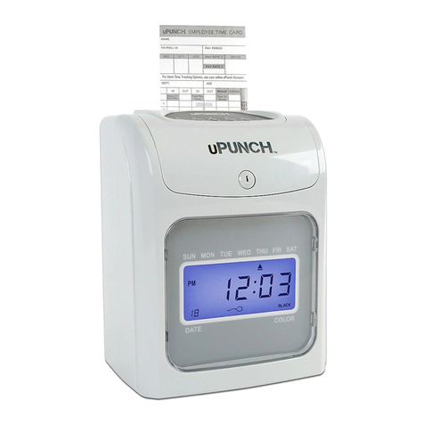
Acroprint Time Recorder Atomic ES900 User manual

Service Manual
QUARTZ TIME RECORDER
ATOMIC
ES900
Acroprint Time Recorder Co.
5640 Departure Drive
Raleigh, NC 27616 USA
Phone: (919) 872-5800
06-0380-000 Rev. B Fax: (919) 850-0720

Service Manual
Service ManualService Manual
Service Manual
CO TE TS
CO TE TSCO TE TS
CO TE TS
1. OUTLINE……………………………………………………………………………………1-1
2. BLOCK DIAGRAM…………………………………………………………………………2-1
3. DISASSEMBLY AND REASSEMBLY OF BASIC PARTS………………………………..3-1
3-1. Exploded View......................................................................……….................. ……......3-2
3-2. Tools Required…………………………………………………………………………..3-3
3-3. Disassembly……………………………………………………………………………...3-4
4. DISASSEMBLY AND REASSEMBLY OF MECHANISM………………………………….4-1
4-1. Exploded View,Oiling Instruction Diagram…………………………..…………………4-2
4-2. Tools,Oils and Detergent Required………………………………………………………4-3
4-3.Disassembly………………………………………………………………………………4-4
4-4.Reassembly………………………………………………………………………….……4-5
5. TROUBLESHOOTING………………………………………………………………………..5-1
5-1.No Operation……………………………………………………………………………... 5-2
5-2.No Display on the LCD Panel………………………………………………… ………… 5-3
5-3.Setting Switch Malfunctioning…………………………………………………………… 5-4
5-4.Motor Operation Failure…………………………………………………………………...5-5
5-5.No Printing……………………………………………………………………………….. 5-6
5-6.Lighting Abnormality……………………………………………………………………...5-7
5-7.Atomic Failure……………………………………………………………………………. 5-8
5-8.How to locate Problems from the Error Codes……………………………………………5-9
6. MEASUREMENT…………………………………………………………………………….6-1
6-1.Voltage Check………………………………………………………………………………..6-2
6-2.Motor Operation Check……………………………………………………………………6-2
6-3.Print Head Resistance Measurement………………………………………………………6-3
7. CONTROL CIRCUIT OPERATION………………………………………………………….7-1
7-1.Control Circuit……………………………………………………………………………..7-2
7-2.Block Diagram of Circuits…………………………………………………………………7-2
7-3.CPU…………………………………………………………………………………………7-3
7-4.Ports List…………………………………………………………… ………………………7-4
7-5.Operation Mode……………………………………………………………….. ……………7-5
7-6.LCD………………………………………………………………………………………….7-6
7-7.Switch………………………………………………………………………………………..7-7
7-8.Sensor…………………………………………………………………….... ……………...7-8
7-9.Encoder…………………………………………………………………………………….. 7-9
7-10.Motor…………………………………………………………………………………….. 7-10
7-11.Print Head………………………………………………………………………………….7-11
8. POWER SUPPLY CIRCUIT……………………………………………………………….....8-1
9. INSPECTION SHEET…………………………………………………………………………..9-1
10. ERROR CODE LIST………………………………………………………………………....10-1
11. CONNECTOR PIN ASSIGNMENT………………………………………………………….11-1
12. CIRCUIT DIAGRAM………………………………………………………………………12-1
13. PARTS LIST…………………………………………………………………………………13-1

1. OUTLI E
Exercise care to avoid electric shock when repairing this unit.
Print position adjuster
The print position from the card edge is
adjustable by pressing and sliding the
print position button on outside bottom
JAN 1
JAN 1
AM
8:00
JAN 1
AM
8:00
30mm
15mm
Front view Cover off
Back view

2. BLOCK DIAGRAM

3. DISASSEMBLY A D REASSEMBLY OF BASIC PARTS
CO TE TS
3-1. Exploded View………………………………………………………………………3-2
3-2. Tools Required………………………………………………………………………3-3
3-3. Disassembly…………………………………………………………………………3-3
3-4. Reassembly…………………………………………………………………………3-7

3-1. Exploded View
Ref No. General-use parts Part No. Ref No. General-use parts Part No.
A
Oval head Screw ST3*12
NTR-07-044
I
CN4 NTR-61-0011
B
Even head Screw ST4*13
NTR-07-048
G
CN2 NTR-61-0027
C
CN5 NTR-61-0026
J
CN3 NTR-61-0030
D
CN10 NTR-61-0059
K
Oval head Screw ST2.6*7 NTR-07-028
E
Switch PCB Ass’y NTR-A3-007
W
Oval head Screw M2.6*6 NTR-07-042A
F
Tray head Screw ST3.0*7
NTR-07-012
3-2. Tools Required
Tools required:
1. No.2or #2 Phillips screwdriver
2. Miniature screwdriver

3-3. Disassembly
Disassemble the parts in the following order:
(1) Top Enclosure (1)
(2) Printer Cover (1)--(2)
(3) Control PCB Ass’y (1)--(2)--(3)
(4) LCD Panel (1)--(2)--(3)--(4)
(5) Mechanism Block (1)--(2)------------(5)
(6) Sensor Switch Ass’y (1)--(2)--(3)------(5)--(6)
(7) Atomic Antenna (1)--(2)--(3)-----(5)--(6)--(7)
8Ni-Cd batteryAss’y (1)--(2)--(3)------(5)--(6)--(7)--(8)
(1) Removing the Top Enclosure
1. Unlock the Lock Lever and remove the Top Enclosure.
Unlock the Lock Lever cannot use,can unlock by pushing two holes of the Top Enclosure rear together
with tweezers that a point is round.
(2) Removing the Printer Cover
1. Remove the cord of DC Adapter Ass’y.
2. Remove two screws A and B holding the printer Cover.
(ScrewA : Oval head Screw ST3.0*12 ,Screw B: Even head Screw ST4*13)

3. Lift the Printer Cover up and turn to the direction of illustration about 90°.
4. Remove harness from the connector of Control PCB Ass’y.
Ref No. General-use parts
Part No. Ref No. General-use parts Part No.
C
CN5 NTR-61-0026
I
CN4 NTR-61-0011
D
CN10 NTR-61-0059
J
CN3 NTR-61-0030
G
CN2 NTR-61-0027

3Removing the Control PCB Ass’y.
1. Remove two screws F holding the Control PCB Ass’y
Screw F :Tray head Screw ST3.0*7 ,2 pieces
2. Remove the Control PCB Ass’y from hook of the Printer Cover by rotating it.
(4).Removing the LCD Panel
1. Remove a tape.
2. After releasing two hooks for the LCD Panel fixing push the LCD from the other side,and remove the LCD
Panel.
*As the hook for fixing is easy to be broken,please do not push with power more than need.

(5) Removing the Mechanism Block
1. Insert the miniature screwdriver in the hole of the Bottom Enclosure back side,and release two hooks for
Paper Rack fixing.
2. Lift some front edges of Paper Rack, and draw out this side.
3. Remove the Key Top.
4. Release harness connecting with Switch PCBAss’y from the hook.
5. Open the hook and release fixing of Switch PCB Ass’y.

6. Remove five screws K holding the Mechanism.
(Screw W: Oval head Screw ST2.6*6:5 Pieces)
7. Remove two screws X holding the Mechanism.
(Screw X: Tray head Screw ST3.0*6:2 Pieces)
8. Remove the Mechanism by rotating to the direction of illustration

(6).
Removing the Sensor Block,Sensor Lever,and Switch PCB Ass,y
1. Move the Sensor Block in the direction shown by arrow A and remove it from the Platen Cover while
pulling it upward.
2. Remove the Sensor Lever with tweezers
3. Release the hook part of the Sensor Block and remove the Switch PCBAss’y.
(7) Removing the Atomic Antenna.

(8)
Remove the Battery Ass’y.
1.
Removing the screw K holding the Battery Cover.
(Screw K: Oval head Screw ST2.6*7)
2. Removing the Battery Cover.
3. Removing the Ni-Cd Battery from the Bottom Enclosure.
3-4.Reassembly
Reassembly of parts is performed by reversing the disassembly procedure.
Note the following points:
a) Make sure that all connectors are properly and securely in place.
b) Take care to avoid catching or cutting the harnesses or cables when mounting parts.
c) Once reassembled check all functions to ascertain that the reassembly procedure had properly
carried out.

4. DISASSEMBLY A D REASSEMBLY OF MECHA ISM
CO TE TS
4-1. Exploded View.Oiling instruction Diagram………………………………………………………………….4-2
4-2. Tools,Oils and Detergent Required…………………………………………………………………………..4-3
4-3. Disassembly…………………………………………………………………………………………………..4-4
4-4. Reassembly…………………………………………………………………………………………………4-12

4-1. Exploded View,Oiling instruction Diagram
Ref No.
General-use parts Part No. Ref No.
General-use parts Part No.
K
Oval head Screw ST2.6*7
NTR-07-028
P
Small Roller copper Sheathing
NTR-A2-010
L
Lead Shaft NTR-A2-016
Q
Motor Shaft NTR-A2-007
M
Lead Screw Shaft NTR-A2-008
R
Sensor Harness B Unit NTR-A3-005
N
Even head Screw M2.5*5
NTR-07-037
S
Oval head Screw ST2.6*7
NTR-07-028
O
Roller NTR-A2-009
T
Carrier Spring NTR-A2-003

4-2. Tools,Oils and Detergent Required
Tools required:
1, No.2 or #2 Phillips screwdriver
2, No.1 or #1 Phillips screwdriver
3, Standard blade type screwdriver with a tip thickness of 1 mm or less
4, Tweezers (for small parts)
Oils required:
1, YM-103(The blade part of Cam and Cam B, Shaft of Platen Plate)
2, SFP-13(Shaft of Cam B,Cam Shaft)
3, N-4K (Guide Shaft)
Detergent required:
1, Alcohol (for cleaning the parts)
*To clean the parts, moisten a soft cloth with alcohol and wipe.Do not dip the parts directly into alcohol.

4-3. Disassembly
Disassembly the parts in the following order:
(1) Ink Ribbon Ass’y (1)
(2) Head Holding Plate (1)--(2)
Print Head
(3) Logo Disk Ass'y (1)--(2)--(3)
Roller
Main Rack
(4) LED PCB Ass’y (1)--(2)--(3)--(4)
(5) Motor Gear (1)--(2)--(3)-----(5)
Cam Gear
Mid Gear
Base Plate Ass’y
Spacer
(6) Bearing (1)--(2)--(3)-------(5)--(6)
Guide Shaft
Carrier Ass’y
Carrier Spring
Carrier Sub Plate
Ribbon Driving Wheel
Clutch Gear
Ribbon Driving Shaft
(7) Lead Screw Shaft (1)--(2)--(3)--------(5)--(6)--(7)
Shank of Cam B
Cam B
Tractor Shaft Spring
Bearing
(8) Sensor Harness B Unit (1)--(2)--(3)-------------------------(8)
(9) Motor Ass’y (1)--(2)--(3)-------(5)--(6)--(7)--(8)--(9)
(10) Sheet (1)--(2)------------(5)---------------------------(10)

(1) Removing the Ink Ribbon Ass’y
1. Hold the handle of the Ink RibbonAss’y and remove it by pulling it sideward.
(2)Removing the Head Holding Plate and Print Head
1. Put the Head Holding Plate in the direction of arrow A with a screwdriver or tweezers and remove it.
2. Pull up the Print Head and remove it in the horizontal direction as shown by arrow B.

(3) Removing Main Rack
1. Remove three screws N holding the Logo Disk Ass’y.
(Screw N: Even head Screw M2.5*5)
2. Remove two logo Disk Ass’y.
3. Remove the Roller.
4. Pull up the Main Rack.
5. Remove the four Spring A.
(4) Remove the LED PCB Ass’y
1. Remove three screws
V
holding the LED PCB Ass’y.
(Screw
V
: Even head Screw ST2.0*3)
2. Remove LED PCB Ass’y.

(5) Removing the Cam Gear,Mid Gear,Cam A, Base PlateAss’y and Paper Pressure Plate Ass’y.
1. Remove the Cam Gear,Mid Gear, Cam A.
2. Remove four screws N holding the Base Plate Ass’y.
(Screw N: Even head Screw M2.5*5)
3. Remove Paper Pressure Plate Ass’y.
(6) Removing the Bearing (this said),Guide Shaft,Carrier Ass’y, Carrier Ass’y,Carrier Spring.
1. Remove one screw K holding the Bearing (this side)
(Screw K: Oval head Screw ST2.6*7)
(3) Remove the Guide Shaft from the Base PlateAss’y.
(4) Remove the Carrier Ass’y from the Base Plate Ass’y.
(5) Remove the Carrier Spring from the Carrier Ass’y.
(6) Remove one screw F holding the Carrier Sub Plate.
(Screw F:
Tray head Screw ST3.0*7)
6. Remove the Ribbon Driving Wheel.Clutch Gear,and Ribbon Driving Shaft.
Table of contents


