Acrow POWERSHORE 30 Quick start guide

TECHNICAL GUIDE
ACROW POWERSHORE 30
FALSEWORK & SHORING

II
Any safety provisions as directed by the appropriate governing agencies must be observed when using our
products. The pictures in this document are snapshots of situations at dierent stages of assembly, and
therefore are not complete images. For the purpose of safety, they should not be deemed as definitive.
The loads featured in this document, related to the parts of the product, are approximate.
The company reserves the right to introduce any modifications deemed necessary for the technical
development of the product.
ALL RIGHTS RESERVED.
Neither all nor part of this document may be reproduced or transmitted in any way by any electronic or
mechanical procedure, including photocopy, magnetic recording or any other form of information storage or
retrieval system without the written permission.
©COPYRIGHT BY ACROW 2023
DOCUMENT NO: ACROWPOWERSHORE30_SEPT2023_ISSUEA

III
POWERSHORE 30
Technical Manual Release Notes
This page is intended to record all changes to the POWERSHORE 30 technical manual pages.
Changes or additions to this manual will be itemised with a brief description and date when the
amendments were made.
ISSUE DATE Amendment Description
ASEPT 2023 First Release

IV
POWERSHORE 30
Contents
1. TECHNICAL SPECIFICATIONS 1.1
System Description 1.1
Purpose of the Document 1.1
Safety Information 1.2
Important Information 1.2
Disclaimer 1.2
Applicable Codes and Standards 1.2
2. GENERAL PRODUCT INFORMATION 2.1
Powershore 30 Components 2.2
Powershore 30 Components 2.3
3. WORKING LOAD LIMITS (WLL) 3.1
Geometrical Considerations 3.2
Summary of Load Charts 3.3
Example 3.4
Top Unrestrained & Bottom Restrained 2 Horizontal Frame Levels 3.5
Top Unrestrained & Bottom Restrained 3 Horizontal Frame Levels 3.6
Top Unrestrained & Bottom Restrained 4 Horizontal Frame Levels 3.7
Top Unrestrained & Bottom Restrained 5 Horizontal Frame Levels 3.8
Top & Bottom Restrained 2 Horizontal Frame Levels 3.9
Top & Bottom Restrained 3 Horizontal Frame Levels 3.10
Top & Bottom Restrained 4 Horizontal Frame Levels 3.11
Top & Bottom Restrained 5 Horizontal Frame Levels 3.12
Single Prop - Top & Bottom Restrained 3.13
Hop Up WLL 3.14
4. SYSTEM DETAILS 4.1
Heights & Horizontal Bracing Frames 4.2
Heights & Horizontal Bracing Frames 4.3
Single Props 4.4
Adjustable Base 4.4
Wedge Jack 4.4
5. ASSEMBLY DETAILS 5.1
Assembling the Powershore Shoring System - Method A 5.2
Assembling the Powershore Shoring System - Method A 5.3
Assembling the Powershore Shoring System - Method B 5.4
Assembling the Powershore Shoring System - Method B 5.5
Method A/B Continued 5.6
Recommended crane lifting points 5.6

V
POWERSHORE 30
Dismantling the Tower 5.7
Dismantling the Tower 5.8
6. TRANSPORT & HANDLING 6.1
Powershore Standards Stillage 6.2
Horizontal Bracing Frames Stillage 6.3
Corner Braces / 600 Tie Bar / Connectors Stillage 6.4
Adjustable Bases Stillage 6.5
Wedge Jack Stillage 6.6
Base Plate / U-head Attachment Stillage 6.7
7. MAINTENANCE & INSPECTION 7.1
Powershore Adjustable Base 7.2
Powershore Base Plate 7.3
Powershore Brace Frame 7.4
Powershore Connector 7.5
Powershore Corner Brace 7.6
Powershore Tie Bar 7.7
Powershore U-Head 7.8
Powershore Wedge Jack 7.9
Powershore Leg 7.10


1.1
POWERSHORE 30
1. Technical Specications
The Acrow POWERSHORE 30 is a high load shoring system that provides a fast, ecient and versatile
supporting structure. The simplicity of the coupling of strong vertical Standards joined together by
Horizontal Bracing Frames enables towers to be easily and safely erected.
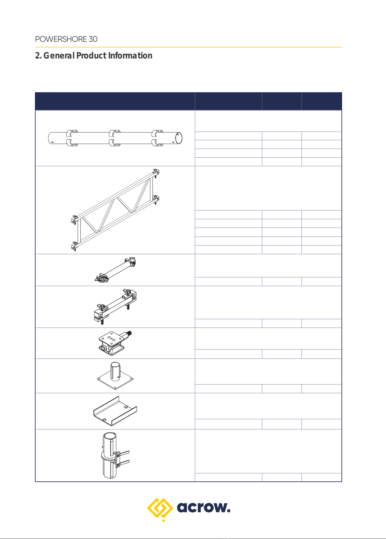
Standards are joined together using a rigid full strength Standard Connector. Corner braces are attached
at apposing corners and alternated between each level to maintain squareness and rigidity of the tower
throughout its height.
Adjustable Bases at the bottom of the tower and Adjustable Bases with U-head attachments at the top
of the tower provide infinite height adjustment. These Adjustable Bases can be braced with a Bracing
Frame as required. The built in strength of each individual component contributes to construction of a
support tower capable of supporting leg load in excess of 300 kN based on tower and bracing frame
configuration.
Acrow POWERSHORE 30 Towers can be configured to support loads up to 1200 kN per tower.
The purpose of this document is to provide guidelines for design, safe handling, transport and installation
of the POWERSHORE 30 system.
The document also outlines the various components of the system and it features illustrations, working
load limits, typical assembly arrangements and safe transport and handling measures.
The information contained in this document is provided as a general guide only and does not replace
the need for the design to be reviewed and checked by a qualified person in the field of temporary works
design and installation, concrete, steel, building construction and services.
This material has been prepared in the context of relevant Australian Standards and the National
Construction Code (NCC). Users should make themselves aware of any recent changes to these
documents referred to therein and to local variations or requirements.
This document is NOT a substitute for site-specific Safe Operation Procedures. It is the Installation
Contractors responsibility to prepare safe work method statements and observe and comply with site
specific health and safety regulations, standards and policies.
Acrow has dedicated engineering services available for project assistance. We can provide design
support for clients to determine the best way to specify and document POWERSHORE 30. Our
technical experts can identify the most ecient temporary work design meeting project requirements,
specifications and installation process.
Should the users require any further information or guidance, they are encouraged to contact their local
Acrow branch.
System Description
Purpose of the Document

1.2
POWERSHORE 30
1. Technical Specications
ELEMENT DESCRIPTION CODE
LOADING Structural Design Actions – General Principles AS/NZS 1170.0-2002
Structural Design Actions – Permanent, Imposed And Other Actions AS/NZS 1170.1-2002
FORMWORK Formwork for Concrete AS 3610-1995
Formwork for Concrete Part 1- Specifications AS 3610.1-2018
The erection and application instructions contained in this manual are the recommended methods to be
used for POWERSHORE 30 products.
The technical function related instructions must be accurately followed to obtain the correct performance
of the product. Any deviation from the recommended usage will require a separate design and/or
verification by Acrow Engineering.
The safe use and application of the system must be in accordance with Australian Standard AS 3610
Formwork for Concrete, Occupational Health & Safety regulations, approved industry codes of practice
and relevant regulatory authority requirements.
The illustrations in these assembly configurations are minimum guidelines only.
The combined use of the POWERSHORE 30 system with equipment from other suppliers may entail
performance issues and therefore requires a design check and/or verification by Acrow Engineering or a
qualified experienced engineer.
Hazard Identification/Risk Assessments for the erection and dismantling of the system are available
from Acrow branches. Site specific Hazard and Risk assessments may need to be generated for specific
projects.
Important Information
The structural design information and guide provided in this document are limited to the relevant codes
nominated below. It does not include certification of any structures or works associated with a project.
The structural design information and guide provided in this document are limited to the relevant codes
nominated below. It does not include certification of any structures or works associated with a project.
Applicable Codes and Standards
Disclaimer
This safety information is to draw the user’s attention to possible musculoskeletal disorders as a result of
manual handling during assembly and dismantling of the POWERSHORE 30 system
It is recommended that users of the POWERSHORE 30 system employ and implement appropriate
procedures and control measures to eliminate or control any risk of Musculoskeletal disorder/injury while
handling.
Refer to the Code of Practice on manual handling published by local Workcover Authority or other
approved and recognised guidelines for correct and appropriate manual handling procedures.
Safety Information

2.1
POWERSHORE 30
2. GENERAL PRODUCT INFORMATION

2.2
POWERSHORE 30
2. General Product Information
Powershore 30 Components
PRODUCT DESCRIPTION PRODUCT
CODE MASS (kg)
Acrow Powershore Standards
1200 Standard APSS12 26.0
1800 Standard APSS18 3 9.0
2400 Standard APSS24 52.0
3000 Standard APSS30 65.0
Acrow Powershore Horizontal Bracing Frames
900 Hoz. Bracing Frame APSF09 24.0
1200 Hoz. Bracing Frame APSF12 31.0
1800 Hoz. Bracing Frame APSF18 41.0
2400 Hoz. Bracing Frame APSF24 51.0
3000 Hoz. Bracing Frame APSF30 61.0
Acrow Powershore Corner Brace
355mm Corner Brace APSCB 2.2
Acrow Powershore 600 Tie Bar
600 Tie Bar APSTB06 5.0
Acrow Powershore Wedge Jack
Wedge Jack WJ50T 12.5
Acrow Powershore Base Plate
Base Plate APSBP 16.5
Acrow Powershore U-Head Attachment
U-Head Attachment APSUH 4.5
Acrow Powershore Standard Connector
Standard Connector APSC 10.0

2.3
POWERSHORE 30
2. General Product Information
Powershore 30 Components
PRODUCT DESCRIPTION PRODUCT
CODE MASS (kg)
Acrow Powershore Adjustable Base
Adjustable Base APSSJ 51.0
Acrow Powershore Hop Up Bracket
Hop-up Bracket APSHUB 9. 4


3.1
POWERSHORE 30
3. WORKING LOAD LIMITS (WLL)

3.2
POWERSHORE 30
3. Working Load Limits (WLL)
Geometrical Considerations
Towers:
Two dierent cases have been considered:
• Case 1: Top unrestrained, bottom restrained towers.
• Case 2: Top and bottom restrained towers.
For each case, dierent configurations have been checked depending on:
Plan dimension: 1.2 m x 1.2 m
• 1.8 m x 1.8 m
• 2.4 m x 2.4 m
• 3.0 m x 3.0 m
Height is measured from the top to bottom of the tower including adjustable bases. In the top unrestrained
condition (ie. case 1) the stability of the load to be supported by Acrow Powershore 30 must be considered
to ensure that it does not have adverse eect on the load capacity of the Acrow Powershore 30 towers.
Generally, overall height is measured from top to bottom of the tower including adjustable bases. However
when stability of the load may be questionable, it would be appropriate to consider the overall height of
the tower to be from the top of unrestrained load to the bottom restrained point of the tower, in case 1 and
check load capacity from the chart for total height.
In the top & bottom restrained condition (ie. Case 2) the overall height of the tower would be the distance
between the restrained points.
Horizontal Bracing frames – the number of horizontal Bracing Frames depends on the tower height , the
maximum distance between Bracing Frames shall not exceed 2.4m:
Load charts on following pages provide working load capacities for towers from 4.6 metres to 14.8 metres
high and for all available plan configuration.
Single Leg Props:
When Acrow Powershore 30 is used as a single leg prop the boundary conditions at the top & bottom of the
prop are considered as being restrained. The chart on page 19 provides working load capacities for prop
height range of 2.8m-10.0m including overall adjustable base extensions.
Tower Height Minimum Horizontal Bracing Frame Levels
4.6 - 5.8m 2
5.8 - 8.8m 3
8.8 - 11.8m 4
11.8 - 14.8m 5

3.3
POWERSHORE 30
3. Working Load Limits (WLL)
Summary of Load Charts
Top unrestrained, bottom restained:
Height 4.6 to 5.8 metres. 2 horizontal frame levels
Height 5.8 to 8.8 metres. 3 horizontal frame levels
Height 8.8 to 11.8 metres. 4 horizontal frame levels
Height 11.8 to 14.8 metres. 5 horizontal frame levels
Top & bottom restrained:
Height 4.6 to 5.8 metres. 2 horizontal frame levels
Height 5.8 to 8.8 metres. 3 horizontal frame levels
Height 8.8 to 11.8 metres. 4 horizontal frame levels
Height 11.8 to 14.8 metres. 5 horizontal frame levels
Single Leg Prop. Height 2.8 to 10.0 metres
• In the top unrestrained condition (ie. case 1) the stability of the load to be supported by Acrow
Powershore 30 must be considered to ensure that it does not have adverse eect on the load capacity
of the Acrow Powershore 30 towers. Generally, overall height is measured from top to bottom of the
tower including adjustable bases. However when stability of the load may be questionable, it would be
appropriate to consider the overall height of the tower to be from the top of unrestrained load to the
bottom restrained point of the tower, in case 1 and check load capacity from the chart for total height. In
the top & bottom restrained condition (ie. Case 2) the overall height of the tower would be the distance
between the restrained points.
• Limit State Load Factor = 1.5
• Towers must be supported on suitably rigid footings to be designed by client.

3.4
POWERSHORE 30
3. Working Load Limits (WLL)
Example
Case: Top unrestrained, bottom restrained
PowerShore 30 Tower overall height (including jacks and unrestrained load) = 8.0m
Plan dimension: 1.80 x 2.40m
• Height 8.0m — 5.80 < 8.0m < 8.80m — 3 horizontal frame levels
• Top unrestrained
• Plan Dimension: 1.80m x 2.40m — 1.80 curve
From Load Chart on Page 3.6
Tower H = 7.60 m — W.L.L. = 142.5 kN
Tower H = 8.20 m — W.L.L. = 130.0 kN
Linear interpolation for overall height of tower & unrestrained load of 8.0m with tower plan
dimensions of 1.80 x 2.40 m:
Q =(142.5 - 130.0) x (8.2 - 8.0)
(8.2 - 7.6) + 130 = 134.2kN

3.5
POWERSHORE 30
3. Working Load Limits (WLL)
Axial Compressive Load Limit per Leg (kN), Q
Tower Height (m)
Top Unrestrained & Bottom Restrained 2 Horizontal Frame Levels
Height from 4.60m - 5.80m

3.6
POWERSHORE 30
3. Working Load Limits (WLL)
Axial Compressive Load Limit per Leg (kN), Q
Tower Height (m)
Top Unrestrained & Bottom Restrained 3 Horizontal Frame Levels
Height from 5.80m - 8.80m

3.7
POWERSHORE 30
3. Working Load Limits (WLL)
Axial Compressive Load Limit per Leg (kN), Q
Tower Height (m)
Top Unrestrained & Bottom Restrained 4 Horizontal Frame Levels
Height from 8.80m - 11.80m

3.8
POWERSHORE 30
3. Working Load Limits (WLL)
Axial Compressive Load Limit per Leg (kN), Q
Tower Height (m)
Top Unrestrained & Bottom Restrained 5 Horizontal Frame Levels
Height from 11.80m - 14.80m
Table of contents