HEK PLM Series User manual

USERS MANUAL
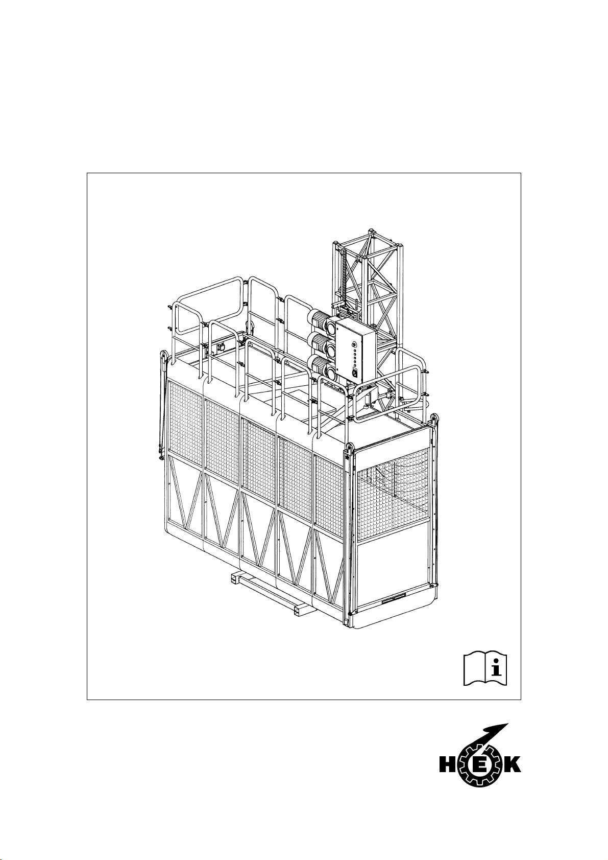
PASSENGER HOIST SERIES-PLM
8995-026
Issue: 02 -1999

II PLM / 8995-026
© 1999, Hek Manufacturing B.V., Middelbeers, The Netherlands
Nothing contained in this publication may be copied and/or published by means of
printing, photocopying, microfilm or any other method, without prior written
permission from Hek Manufacturing B.V.
Drawings and photographs are illustrative only and do not necessarily show the design of the product on
the market at any given point of time.

IIIPLM / 8995-026
HEK PASSENGER HOIST
Type number : .........................
Serial nummer : .........................
Machine number : .........................
Motor carriage number : .........................
Year of manufacture : .........................
Owner : .........................
HEK Manufacturing B.V.
Westelbeersedijk 18 P.O. Box 2
5091 SM Middelbeers 5090 AA Middelbeers
The Netherlands The Netherlands
Tel : +31(0)13 51 48 653
Fax : +31(0)13 51 48 630

IV PLM / 8995-026

VPLM / 8995-026
FOREWORD
Read this instruction manual carefully before using the
passenger hoist.
Take all safety precautions into account!
FOREWORD
The passenger hoist is equipped with a
rack-and-pinion drive.
The hoist can be quickly moved and is
easy to transport.
The height of the mast, which consists of
separate elements, can easily be
adjusted to suit the working level. The
mast can be easily and safely assembled
from the roof of the cabin.
The control system makes it possible to
stop the PLM hoist at any desired height.
Considerable attention has been given to
safety aspects in the construction of this
hoist.
Depending on the area of application, a
choice can be made from various types
of masts, cabin lengths and maximum
loads.
This instruction manual describes only
the basic machine, incl. landing
protection systems in the standard form
in which it is supplied by HEK
Manufacturing BV.

VI PLM / 8995-026
CONTENTS
CONTENTS
FOREWORD V
CONTENTS VI
SURVEY OF ILLUSTRATIONS VII
SURVEY OF STANDARDS VIII
MEANING OF THE SYMBOLS USED IX
1. TECHNICAL DETAILS 1-1
1.1 PLM Vrk 500-mast 1-3
1.2 PLM Vrk 700-mast 1-6
1.3 Anchor forces 1-9
2. DESCRIPTION OF COMPONENTS 2-1
2.1 General description 2-1
2.2 Transition from cabin to landing 2-3
3 SAFETY 3-1
3.1 General 3-1
3.2 Safety before use 3-1
3.3 Safety during use 3-1
3.4 Safety after use 3-2
3.5 Built-in and attached
protective devices 3-2
3.6 Protective devices to be installed 3-3
3.7 Personnel 3-4
4. TRANSPORT 4-1
5. CONTROL UNITS 5-1
5.1 Connection plug for
power supply cable 5-1
5.2 Ground station switchbox 5-1
5.3 Switchbox cabin 5-2
5.4 Automatic control box 5-4
5.5 Switch box cabin roof 5-5
5.6 Drop test control box (optional) 5-6
5.7 Emergency stop in ground cage 5-6
6. ASSEMBLY AND ANCHORING 6-1
6.1 Preparation for assembly 6-2
6.2 Ground support 6-3
6.3 Positioning the basic unit 6-4
6.4 Assembly of the mast 6-7
6.5 Anchoring the mast 6-12
6.6. Landing stops 6-13
6.7 Landing protection 6-13
6.7.1 Mounting of the
landing barrier 6-14
7. OPERATION 7-1
7.1 General 7-1
7.2 Preparation 7-2
7.3 Testing 7-3
7.4 Drop test 7-3
7.5 Operation from the cabin 7-5
7.5.1 Joystick control 7-6
7.5.2 Automatic control (optional) 7-7
7.5.3 Pushbutton control 7-7
7.6 Operation from the landing 7-8
7.6.1 One-button landing unit 7-8
7.6.2 Two-button landing unit 7-8
7.6.3 Three-button landing unit 7-9
7.7 Landing barrier 7-10
7.8 Overload protection 7-11
7.9 Fail safe brake 7-11
7.10 Hoist operation in an
emergency situation 7-12
8. DISASSEMBLY AND TRANSPORT 8-1
9. MAINTENANCE 9-1
9.1 Maintenance intervals 9-2
9.2 Motor brake 9-4
9.2.1 General 9-4
9.2.2 Operation 9-4
9.2.3 Maintenance 9-5
9.3 Oil check/change 9-7
9.4 The fail safe brake 9-9
9.4.1 Fail safe brake type 1 9-11
9.4.2 Fail safe brake type 2 9-13
9.5 Testing the overload device 9-14
10. MALFUNCTION ANALYSIS 10-1
11. MACHINE DISPOSAL 11-1
12. LIST OF KEYWORDS 12-1

VIIPLM / 8995-026
CONTENTS
SURVEY OF ILLUSTRATIONS
Fig.1 Main dimensions PLM single X
Fig.2 Main dimensions PLM twin X
Fig.1-1 PLM square 500 mast 1-5
Fig.1-2 PLM square 700 mast 1-8
Fig.2-1 Basic machine PLM 500 2-1
Fig.2-2 Basic machine PLM 700 2-1
Fig.2-3 Cabin carriage 2-2
Fig.2-4 Motor carriage 2-2
Fig.2-5 Crane on cabin roof 2-2
Fig.4-1 Lifting point cabin 4-1
Fig.4-2 Lifting point motor carriage 4-1
Fig.5-1 Groundstation switch box 5-1
Fig.5-2 Control box cabin 5-3
Fig.5-3 Automatic control box 5-4
Fig.5-4 Switch box cabin roof 5-5
Fig.5-5 Drop test control box 5-6
Fig.5-6 Emergency stop in ground cage 5-6
Fig.6-1 Machine positioning 6-1
Fig.6-2 Inspection buffer 6-2
Fig.6-3 Ground support single 6-3
Fig.6-4 Ground support twin 6-3
Fig.6-5 Grond frame and ground cage 6-4
Fig.6-6 Motor bracket 6-5
Fig.6-7 Roof fences 6-5
Fig.6-8 Cabin roof switch box 6-9
Fig.6-9 Crane on roof 6-9
Fig.6-10 Distance above cabin 6-11
Fig.6-11 Cabin roof switch box 6-11
Fig.6-12 Distance landing barrier 6-13
Fig.6-13 Positioning landing barrier 6-14
Fig.6-14 Landing barrier front view 6-15
Fig.7-1 Switch box cabin 7-4
Fig.7-2 Droptest control box 7-4
Fig.7-3 Switch box roof 7-5
Fig.7-4 Control box cabin 7-6
Fig.7-5 Automatic control box 7-7
Fig.7-6 Control box cabin 7-8
Fig.7-7 Landing barrier opened 7-10
Fig.7-8 Landing barrier closed 7-10
Fig.7-9 Warning light overload 7-11
Fig.7-10 Motor brake release lever 7-12
Fig.8-1 Motor brake release lever 8-2
Fig.8-2 Motor bracket 8-3
Fig.8-3 Crane on cabin roof 8-3
Fig.8-4 Roof fences 8-3
Fig.9-1 Inspection buffer 9-1
Fig.9-2 Motor brake 9-4
Fig.9-3 Motor brake 9-5
Fig.9-4 Positioning of feeler gauge 9-6
Fig.9-5 Fail safe brake 9-8
Fig.9-6 Fail safew brake type 1 9-10
Fig.9-7 Fail safe brake type 2 9-12
Fig.9-8 Control light overload 9-14

VIII PLM / 8995-026
SURVEY OF STANDARDS
SURVEY OF STANDARDS
The following standards and directions have been considered in the construction:
prEN 12159 Passenger and material hoists
EN 60204-1 Electrical equipment of machines
EMC direction 89/336/EG

IXPLM / 8995-026
SYMBOLS
MEANING OF THE SYMBOLS USED
WARNING
Failing to (exactly) comply with
working or operating
instructions may lead to
serious injury, fatal accident,
severe mechanical damage or
operating losses.
During use, no person may
stand under the machine.
Danger: high voltage.
Danger of falling objects.
Suggestion or advice to enease
certain procedures.

X PLM / 8995-026
Fig.1 Main dimensions PLM single Fig.2 Main dimensions PLM twin

TECHNICAL DETAILS
1-1PLM / 8995-026
1. TECHNICAL DETAILS
Note:
The specifications and restrictions below are based on standard applications. Under
certain circumstances, the actual specifications may be amended. In such cases,
written permission of the manufacturer is obligatory.
See figure 1 and 2.
Explanation ot the type codes used:
The type code is PLM AABC:
AA= the max. lifting capacity, C= the cabin length
e.g. AA = 10 = 1000 kg, e.g. 1 = 1,6 m
AA = 15 = 1500 kg. 2 = 2,4 m
B= the mast type, 3 = 3,2 m
5 = 500 square mast, 4 = 4,0 m
7 = 700 square mast. 6 = 3,2 m TWIN
8 = 4,0 m TWIN
Hoist type
3/0
3/0
3/0
3/0
3/0
Load (incl. persons) [kg.] 1000 1000 1000 1500 1500
Number of persons 12 12 12 18 18
Speed [m/min] 40 40 40 40 40
Number of motors 2 2 2 3 3
Max. mast height [m] A 200 200 200 200 200
Max. anchor distance [m] B 12 12 9 12 9
Height of first anchor [m] C 6 6 4.5 6 4.5
Max. mast height above last anchor [m] D 6 6 4.5 6 4.5
Height ground cage [m] E 2.5 2.5 2.5 2.5 2.5
Height cabin [m] F 2.75 2.75 2.75 2.75 2.75
Height cabin interior [m] G 2.2 2.2 2.2 2.2 2.2
Height railings [m] H 1.15 1.15 1.15 1.15 1.15
Height ground cage door [m] 3.25 3.25 3.25 3.25 3.25
Height cabin floor to ground [m] 0.5 0.5 0.5 0.5 0.5
Max. wind force during assembly 12.5 m/s (6 Beaufort)
Max. wind force during use 20 m/s (8 Beaufort)
Type mast VRK
500 VRK
500 VRK
500 VRK
500 VRK
500

TECHNICAL DETAILS
1-2 PLM / 8995-026
See figure 1 and 2.
Explanation ot the codes used:
The code is PLMAABC:
AA= the max. lifting capacity, C= the cabin length
e.g. AA = 10 = 1000 kg, e.g. 1 = 1,6 m
AA = 15 = 1500 kg. 2 = 2,4 m
B= the mast type, 3 = 3,2 m
5 = 500 square mast, 4 = 4,0 m
7 = 700 square mast. 6 = 3,2 m TWIN
8 = 4,0 m TWIN
Hoist type
3/0
3/0
3/0
3/0
3/0
3/0
3/0
3/0
3/0
Load (incl. persons) [kg.] 1000 1000 1500 1500 2000 2000 2 x
1000 2 x
2000 2 x
2000
Number of persons 12 12 18 18 25 25 2 x
12 2 x
25 2 x
25
Speed [m/min] 40 40 40 40 40 40 40 40 40
Number of motors 2 2 3 3 3 3 2 x 2 2 x 3 2 x 3
Max. mast height [m] A 200 200 200 200 200 200 200 200 200
Max. anchor distance [m] B 12 12 12 12 12 12 12 12 9
Height of first anchor [m] C 6 6 6 6 6 6 6 6 4.5
Max. mast height above last anchor [m] D 6 6 6 6 6 6 6 6 4.5
Height ground cage [m] E 2.5 2.5 2.5 2.5 2.5 2.5 2.5 2.5 2.5
Height cabin [m] F 2.75 2.75 2.75 2.75 2.75 2.75 2.75 2.75 2.75
Height cabin interior [m] G 2.2 2.2 2.2 2.2 2.2 2.2 2.2 2.2 2.2
Height railings [m] H 1.15 1.15 1.15 1.15 1.15 1.15 1.15 1.15 1.15
Height ground cage door [m] 3.25 3.25 3.25 3.25 3.25 3.25 3.25 3.25 3.25
Height cabin floor to ground [m] 0.5 0.5 0.5 0.5 0.5 0.5 0.5 0.5 0.5
Max. wind force during assembly 12.5 m/s (6 Beaufort)
Max. wind force during use 20 m/s (8 Beaufort)
Type mast VRK
700 VRK
700 VRK
700 VRK
700 VRK
700 VRK
700 VRK
700 VRK
700 VRK
700

TECHNICAL DETAILS
1-3PLM / 8995-026
1.1 PLM Vrk 500-mast
General
Electrical installation
(The information below is per cabin)
Length mast element 1508 mm
Width and height mast element 500 x 500 mm
Weight mast element 78 kg
Module 5
Mast bolts M16 x 190 kwal. 10.9
Torque 200 Nm
Distance between cable guides 6 m
Sound level <70 dB
Hoist type
3/03/0
3/0 3/03/0
Number of motors 2 3
Nominal power (25% duty cycle) 10.5 kW 10.5 kW
Nominal power ( 40% duty cycle) 9.2 kW 9.2 kW
Max. starting current 240 A 360 A
Power consumption during start 140 kVA 200 kVA
Power consumption 30 kVA 45 kVA
Power supply voltage 400 V ± 5% 400 V ± 5%
Phases 3 + N + Pe 3 + N + Pe
Frequency of power supply voltage (depending on national
conditions with rergard to power supply voltage) 50 or 60 Hz 50 or 60 Hz
Building site fuse (slow) 50 A 80 A (65 A under ideal
circumstances)
Control voltage 42 Vac 42 Vac
Frequency of control voltage 50/60 Hz 50/60 Hz
Power supply cable (building site to machine)
up to 50m 5 x 16 mm² 5 x 25 mm²
up to 75m 5 x 25 mm² 5 x 35 mm²
up to 110m 5 x 35 mm² ------
Machine cable (drum cable)
up to 110m 5 x 10 mm² + 8 x 1.5 mm² 5 x 16 mm² + 8 x 1.5 mm²
up to 160m 5 x 16 mm² + 8 x 1.5 mm² ------
up to200m 5 x 16 mm²+ 8 x 1.5 mm² with cable trolley
Accessories socket 220 V / 16 A 220 V / 16 A

TECHNICAL DETAILS
1-4 PLM / 8995-026
Dimensions and weights
See figure 1-1.
A [mm] B [mm] C [mm] D [mm] E [mm] F [mm] G [mm] H [mm]
PLM 1051 1630 1400 1500 2100 945 1650 1770 660
PLM 1052 1430 1400 1500 2900 945 2460 2580 460
PLM 1053 1430 1400 1500 3700 945 3260 3380 460
PLM 1552 1430 1400 1500 2900 945 2460 2580 460
PLM 1553 1430 1400 1500 3700 945 3260 3380 460
Weight basic machine [kg]
exc. motor carriage incl.
2 masts and ground frame
Weight motor carriage [kg]
incl. 1 mast
Dimensions basic machine
incl. ground cage (lxwxh) [mm]
Dimensions basic machine
exc. ground cage (lxw) [mm]
Dimensions motor carriage
incl. 1 mast (lxwxh) [mm]
+RLVWW\SH
Dimensions and weights
PLM 1051 1210 610 2100 x 2400 x 3250 1770 x 1500 1110 x 920 x 1508
PLM 1052 1340 610 2900 x 2400 x 3250 2580 x 1500 1110 x 920 x 1508
PLM 1053 1460 610 3700 x 2400 x 3250 3380 x 1500 1110 x 920 x 1508
PLM 1552 1340 800 2900 x 2400 x 3250 2580 x 1500 1110 x 920 x 1508
PLM 1553 1460 800 3700 x 2400 x 3250 3380 x 1500 1110 x 920 x 1508

TECHNICAL DETAILS
1-5PLM / 8995-026
Fig.1-1 PLM square 500 mast

TECHNICAL DETAILS
1-6 PLM / 8995-026
1.2 PLM Vrk 700-mast
General
Electrical installation
(The information below is per cabin)
Length mast element 1508 mm
Width and height mast element 700 x 700 mm
Weight mast element 109, voor Twin 134 kg
Module 8
Mast bolts M20 x 200 kwal. 10.9
Torque 240 Nm
Distance between cable guides 6 m
Sound level <70 dB
Hoist type
3/03/0
3/0
3/03/0
3/03/0
3/03/0
Number of motors 2 3
Nominal power (25% duty cycle) 10.5 kW 10.5 kW
Nominal power ( 40% duty cycle) 9.2 kW 9.2 kW
Max. starting current 240 A 360 A
Power consumption during start 140 kVA 200 kVA
Power consumption 30 kVA 45 kVA
Power supply voltage 400 V ± 5% 400 V ± 5%
Phases 3 + N + Pe 3 + N + Pe
Frequency of power supply voltage (depending on national
conditions with rergard to power supply voltage) 50 or 60 Hz 50 or 60 Hz
Building site fuse (slow) 50 A 80 A (65 A under ideal
circumstances)
Control voltage 42 Vac 42 Vac
Frequency of control voltage 50/60 Hz 50/60 Hz
Power supply cable (building site to machine)
up to 50m 5 x 16 mm² 5 x 25 mm²
up to 75m 5 x 25 mm² 5 x 35 mm²
up to 110m 5 x 35 mm² ------
Machine cable (drum cable)
up to 110m 5 x 10 mm² + 8 x 1.5 mm² 5 x 16 mm² + 8 x 1.5 mm²
up to 160m 5 x 16 mm² + 8 x 1.5 mm² ------
up to 200m 5 x 16 mm² + 8 x 1.5 mm² with cable trolley
Accessories socket 220 V / 16 A 220 V / 16 A

TECHNICAL DETAILS
1-7PLM / 8995-026
A [mm] B [mm] C [mm] D [mm] E [mm] F [mm] G [mm] H [mm]
PLM 1072 1650 1400 1500 2900 1500 2460 2580 660
PLM 1073 1650 1400 1500 3700 1500 3260 3380 660
PLM 1572 1650 1400 1500 2900 1500 2460 2580 660
PLM 1573 1650 1400 1500 3700 1500 3260 3380 660
PLM 2073 1650 1400 1500 3700 1500 3260 3380 660
PLM 2074 1650 1400 1500 4500 1500 4070 4190 660
PLM 1076 2500 1400 1500 3700 1500 3260 3380 660
PLM 2076 2500 1400 1500 3700 1500 3260 3380 660
PLM 2078 2500 1400 1500 4500 1500 4070 4190 660
Dimensions and weights
See figure 1-2.
+RLVWW\SH
Dimensions and weights
PLM 1072 1510 650 2900 x 2600 x 3250 2580 x 1500 1110 x 1120 x 1508
PLM 1073 1620 650 3700 x 2600 x 3250 3380 x 1500 1110 x 1120 x 1508
PLM 1572 1510 840 2900 x 2600 x 3250 2580 x 1500 1110 x 1120 x 1508
PLM 1573 1620 840 3700 x 2600 x 3250 3380 x 1500 1110 x 1120 x 1508
PLM 2073 1620 840 3700 x 2600 x 3250 3380 x 1500 1110 x 1120 x 1508
PLM 2074 1750 840 4500 x 2600 x 3250 4190 x 1500 1110 x 1120 x 1508
PLM 1076 2880 1210 3700 x 2400 x 3250 3380 x 1500 1400 x 1540 x 1508
PLM 2076 2880 1590 3700 x 4400 x 3250 3380 x 1500 1400 x 1540 x 1508
PLM 2078 3130 1590 4500 x 4400 x 3250 4190 x 1500 1400 x 1540 x 1508
Weight basic machine [kg]
exc. motor carriage incl.
2 masts and ground frame
Weight motor carriage [kg]
incl. 1 mast
Dimensions basic machine
incl. ground cage (lxwxh) [mm]
Dimensions basic machine
exc. ground cage (lxw) [mm]
Dimensions motor carriage
incl. 1 mast (lxwxh) [mm]

TECHNICAL DETAILS
1-8 PLM / 8995-026
Fig.1-2 PLM square 700 mast

TECHNICAL DETAILS
1-9PLM / 8995-026
1.3 Anchor forces
For details, formulas, calculations and
other information regarding the
applicable anchoring forces and
anchoring possibilities, please refer to
your dealer.

COMPONENTS
2-1PLM / 8995-026
2. DESCRIPTION OF COMPONENTS
2.1 General description
The basic rack-and-pinion passenger
hoist set consists of the following five
main components:
* ground station (cage, door and frame)
* mast
* cabin carriage
* motor carriage
* control system
The cabin carriage is guided along the
mast by means of Nylontron rollers and is
mounted in a C-frame construction in
which cages of different dimensions can
be fitted.
A fail safe brake is mounted on the cabin
carriage (see fig. 2-3). If the pre-
determined speed of descent is
exceeded, the fail safe brake brings the
cabin to a stop, prevents it from
descending further and also switches off
the motor carriage.
The motor carriage (see fig. 2-4) is
equipped with two or three electric
motors. The motor carriage is moved
along the mast by means of one pinion
per motor and a rack. The motor carriage
can easily be coupled to a hoist to reduce
the transport heigtht.
Plugs are used for all electrical
connections which must be broken for
transport purpose.
Fig.2-1 Basic machine PLM 500
Fig.2-2 Basic machine PLM 700
This manual suits for next models
14
Other HEK Construction Equipment manuals