Actia TGU-R ACCESS User manual
P218703
ADt 001 M
B
Headquarters
Industrial site
Chartres sSite
5, rue Jorge Semprun - B.P. 74215
31432 TOULOUSE cedex 4 (FRANCE)
Tél. +33 (0)5 61 17 61 61
Fax + 33 (0)5 61 55 42 31
10, avenue Edouard Serres –Parc aéronautique - B.P. 60112
31772 COLOMIERS cedex (FRANCE)
Tél. +33 (0)5 62 74 34 00
Fax + 33 (0)5 62 74 34 34
8, rue Réaumur –Jardin
d’entreprises
28000 CHARTRES (FRANCE)
Tél. +33 (0)2 37 33 34 00
Fax + 33 (0)2 37 33 34 35
© 2021 « Any reproduction of this document whether total or partial without the written consent of ACTIA Automotive is forbidden”
TGU-R ACCESS USER MANUAL
Par
Date
Visa
Reference
Revision
Author
Lionel Royané
P218703
B
Checker
Jerome Gibert
Wajdi Zairi
Approver
Lionel Royané
Quality
Célie Maris
Classification
Internal distribution
External distribution
☐Without
☒Confidential Actia
☒Confidential Client
☐Confidential supplier
Recipient name
Services
Recipient name
Services
dc=local, dc=actia, ou=Actia Automotive, ou=01 - Utilisateurs,
2021.06.01 15:57:09 +02'00'
2021.06.02 11:01:16 +02'00'
WAJDI ZAIRI
Signature numérique de WAJDI ZAIRI
Date : 2021.06.03 18:19:38 +01'00'
dc=local, dc=actia, ou=Actia Automotive, ou=01 - Utilisateurs, cn=lroyane,
2021.06.09 15:20:37 +02'00'
2021.06.09 17:01:26 +02'00'

P218703
ADt 001 M
B
© 2021 « Any reproduction of this document whether total or partial without the written consent of ACTIA Automotive is forbidden”
Page 2sur 37
EVOLUTION TRACKING SHEET
Index
Pages ou éléments
concernés
Date
Evolution nature and motive
-
All
VII.8.5
0
VI.1
2019-12-10
2020-03-10
2020-03-10
2020-04-10
Creation of document TGU-R ACCESS USER MANUAL
Add Led chronograms
Add initial customer SW download operation procedure
Add recommended max storage duration for battery pack option
A
IV.4
IV.4
IV.4
VIII.1
Front page
VI.3
VI.4
XI
XI
2020-09-11
2020-09-11
2020-09-11
2020-09-11
2020-09-11
2020-09-14
2020-09-14
2020-09-15
2020-09-18
4G US variant: ALS3-US *Only 900 and 1800 are available in Europe
WiFi 5GHz Frequency range: 5180-5825MHz (limited to 5470-5725MHz in
Europe)
Note added on operating temperature range for NAD tests according to 3GPP
standard
WiFi 2,4GHz => WLAN 2,4GHz
Luce site => Chartres site
SIM card selection criterias added
Network operator selection criterias added
Additional export control information and recommendation added
Update on list of cryptographic algorithms
B
V.1
II.2
IV.2
IV.3
IV.4
V.1
VI.4
XI
VIII.1
0
VII.8.1
VII.8.2
VII.8.3
VII.8.4
VII.4
IV.4
VII.8.5
VII.8.6
2021-01-04
2021-03-17
2021-03-17
2021-03-17
2021-03-17
2021-03-22
2021-03-22
2021-03-22
2021-03-22
2021-03-22
2021-03-23
2021-03-23
2021-03-23
2021-03-23
2021-05-03
2021-05-03
2021-05-03
2021-06-01
Correction on USB –Ethernet position
Add reference document TGU-R Security Manual
Audience chapter updated to add additional REF documents
Description updated with more details on vehicle interfaces
Add 4G W variant specific feature list and NAD PLS83-W
CN1 connector pinout update to add specific configuration for 4G W variants
Specific handling for AT&T SIM cards with annual IMEI list reporting by customer
cryptographic table updated on NAD modules + added for optional HSM
Type approval chapter updated to add new 4G W variant + update on 4G EU
Inviolability label removal instructions added
Update to add more recommendation for initial SW download process
Chapter added for OTA updates recommendations
Chapter added for NAD module management
Chapter added for power supply and temperature alerts management
Fuse caliber chapter updated to add specific application use case for IEC 62368-
1 safety standard applicable for CE marking and other countries based on it.
Voltage range updated for 48V variant (16V min instead of 6V) to avoid to break
1.5A fuse required by new IEC 62368-1 safety standard applicable for CE
marking
Chapter added on signal termination management
Chapter added on WIFI channel management

P218703
ADt 001 M
B
© 2021 « Any reproduction of this document whether total or partial without the written consent of ACTIA Automotive is forbidden”
Page 3sur 37
TABLE OF CONTENTs
IPRÉSENTATION ....................................................................................................................................5
I.1 DOCUMENT SUBJECT.........................................................................................................................................5
I.2 APPLICATION DOMAIN......................................................................................................................................5
I.3 DOCUMENT DESCRIPTION ..................................................................................................................................5
I.4 DOCUMENT LOCATION ......................................................................................................................................5
II DOCUMENTS........................................................................................................................................6
II.1 APPLICABLE DOCUMENTS ..................................................................................................................................6
II.2 REFERENCE DOCUMENTS ...................................................................................................................................6
III TERMINOLOGY.....................................................................................................................................7
III.1 ABBREVIATIONS...............................................................................................................................................7
III.2 GLOSSARY ......................................................................................................................................................7
IV INTRODUCTION....................................................................................................................................7
IV.1 SCOPE ...........................................................................................................................................................7
IV.2 AUDIENCE ......................................................................................................................................................7
IV.3 PRODUCT DESCRIPTION .....................................................................................................................................8
IV.4 PRODUCT FEATURE LIST.....................................................................................................................................9
VPRODUCT INTERFACES DESCRIPTION .................................................................................................14
V.1 CONNECTORS................................................................................................................................................14
V.2 BATTERY AND SIM CARD ..................................................................................................................................16
VI PRODUCT OPERATION........................................................................................................................17
VI.1 TRANSPORTATION AND STORAGE: .....................................................................................................................17
VI.2 HANDLING:...................................................................................................................................................17
VI.3 SIM CARD:...................................................................................................................................................17
VI.4 NETWORK OPERATOR: ....................................................................................................................................17
VII INSTALLATION....................................................................................................................................18
VII.1 POWER DISSIPATION:......................................................................................................................................18
VII.2 MECHANICAL CONSTRAINTS .............................................................................................................................18
VII.3 CONNECTORS AND WIRING : ............................................................................................................................19
VII.4 FUSES:.........................................................................................................................................................19
VII.5 CAN LINES ...................................................................................................................................................20
VII.6 ELECTROMAGNETIC COMPATIBILITY ...................................................................................................................21
VII.7 ECU PROTECTION ..........................................................................................................................................21
Load dump protection......................................................................................................................................... 21
Reverse battery protection ................................................................................................................................. 21
VII.8 SW MANAGEMENT ........................................................................................................................................22
Initial SW download............................................................................................................................................. 22
OTA SW download............................................................................................................................................... 22
NAD module ........................................................................................................................................................ 22
Power supply and temperature alerts management .......................................................................................... 22
Signal termination management......................................................................................................................... 22
WIFI channels management................................................................................................................................ 22
VII.9 LEDS FUNCTIONALITY ......................................................................................................................................23
VII.10 BATTERY PACK REPLACEMENT AND SIM CARD INSTALLATION PROCEDURE: ................................................................25
VII.11 ANTENNAS: ..................................................................................................................................................27
VII.12 INVIOLABILITY LABEL REPLACEMENT:..................................................................................................................28
VIII COUNTRIES REGULATIONS: ................................................................................................................30

P218703
ADt 001 M
B
© 2021 « Any reproduction of this document whether total or partial without the written consent of ACTIA Automotive is forbidden”
Page 4sur 37
VIII.1 TYPE APPROVAL.............................................................................................................................................30
VIII.2 DANGEROUS GOODS TRANSPORTATION REGULATION (ATEX):................................................................................33
IX AFTER SALES.......................................................................................................................................33
IX.1 ECU REPLACEMENT........................................................................................................................................33
IX.2 WARRANTY ..................................................................................................................................................34
XSAFETY INFORMATION ON BATTERY PACK.........................................................................................35
XI EXPORT CONTROL ..............................................................................................................................36
XII EXPORT HS CODE ...............................................................................................................................37
Table of tables
TABLE 1 : ABBREVIATIONS.............................................................................................................................................................. 7
TABLE 2 : GLOSSARY ..................................................................................................................................................................... 7

P218703
ADt 001 M
B
© 2021 « Any reproduction of this document whether total or partial without the written consent of ACTIA Automotive is forbidden”
Page 5sur 37
IPRÉSENTATION
I.1 DOCUMENT SUBJECT
This manual presents the hardware features of TGU-R, assisting you to install it in safe way and ensure good operation in
the vehicle.
I.2 APPLICATION DOMAIN
This manual is intended to owners or drivers operating TGU-R product.
I.3 DOCUMENT DESCRIPTION
This document includes:
Product features overview
Connectors interfaces
Battery pack interface
SIM card connector interface
Product installation
Product certification
I.4 DOCUMENT LOCATION
Project folder: \\VM-FILE-SERVER1\projets\8000\8186\8186-03 (TGU-R Access)\02 - System
Copy available for registered people on ACTIA City Delivery Street: TGU-R ACCESS

P218703
ADt 001 M
B
© 2021 « Any reproduction of this document whether total or partial without the written consent of ACTIA Automotive is forbidden”
Page 6sur 37
II DOCUMENTS
II.1 APPLICABLE DOCUMENTS
NA
II.2 REFERENCE DOCUMENTS
Link
Document reference
Document title
REF1
P215806
TGU-R ACCESS Product Specification
REF2
P110149P01
TGU-R ACCESS Interface Drawing
REF3
REF4
REF5
REF6
P216166
P217767
AC521209
P218077
TGU-R ACCESS Host CPU API Specification
TGU-R ACCESS Customer Setup Manager software specification
AC16 BATTERY SPARE PART MAINTENANCE INSTRUCTION MANUAL
TGU-R ACCESS external antenna specification
REF7
P218723
TGU-R Security Manual

P218703
ADt 001 M
B
© 2021 « Any reproduction of this document whether total or partial without the written consent of ACTIA Automotive is forbidden”
Page 7sur 37
III TERMINOLOGY
III.1 ABBREVIATIONS
ATEX
ATmospheres EXplosives according to European regulation
BAT
Battery
BW
BandWidth
CAN
Controller Area Network
ESD
Electro Static Discharge
GND
Ground
GSM
Global System for Mobile Communications
GNSS
Global Navigation Satellite System
IEA
Industrial Environment Agreement
PAA
Part Application Approval
SIM
Subscriber Identity Module
WLAN
Wireless Local Area Network
Table 1 : abbreviations
III.2 GLOSSARY
Heart beat
It is a periodic signal from processor informing application that the system is still alive
Table 2 : glossary
IV INTRODUCTION
IV.1 SCOPE
This document provides TGU-R ACCESS short description and recommendation to insure correct vehicle installation and
interface.
The warranty on the product will not be applicable if the instructions described in this user manual are not followed.
TGU-R ACCESS installation in customer factory and vehicle must be checked by ACTIA during the IEA and PAA to confirm
that it is aligned with this user manual recommendations and product specification.
PAA and IEA must be carried out for each new vehicle architecture.
During the vehicle life, any change in the vehicle architecture that could impact TGU-R ACCESS installation and operation
must be reported to ACTIA.
IV.2 AUDIENCE
This manual is intended to owners or drivers without professional or specialized knowledge on TGU-R ACCESS product.
This manual doesn’t replace TGU-R ACCESS product specifications (REF1 + REF2 + REF3 + REF4 + REF5 + REF6 + REF7)
which remains the reference.
P218703
ADt 001 M
B
© 2021 « Any reproduction of this document whether total or partial without the written consent of ACTIA Automotive is forbidden”
Page 8sur 37
IV.3 PRODUCT DESCRIPTION
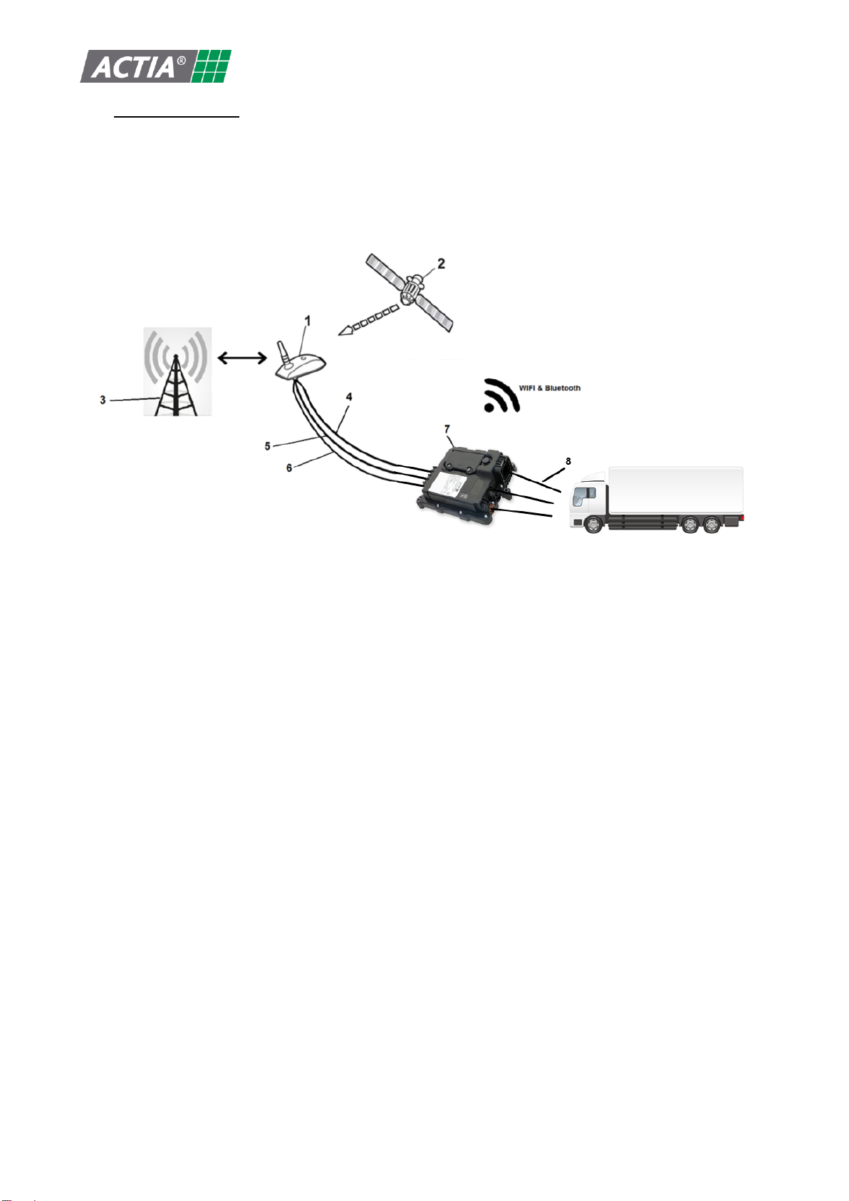
TGU-R ACCESS is a rugged telematics unit intended to be used for fleet management, data logging, diagnostic, and lots of
other applications requiring data exchange between vehicle interfaces (CAN network, USB, Ethernet, LIN, K-line, I-button,
RS232) and wireless networks GSM / WIFI / BT. It is also providing GNSS positioning
1. GSM/GNSS/WIFI external antenna
2. GNSS satellite
3. Network operator antenna
4. GNSS antenna cable
5. GSM antenna cable
6. WIFI antenna cable
7. TGU-R ACCESS product (including internal antennas: WIFI, Bluetooth, GSM receive diversity)
8. Vehicle interfaces:
a. Main interface including power supply, inputs, outputs, CAN bus interfaces, LIN, RS232, I-button
b. Ethernet interface
c. USB interface

P218703
ADt 001 M
B
© 2021 « Any reproduction of this document whether total or partial without the written consent of ACTIA Automotive is forbidden”
Page 9sur 37
IV.4 PRODUCT FEATURE LIST
Product features (see REF1 for more details)
Wireless interfaces
NAD module :
3G variant: PHS8-P from Thales(ex Gemalto-Cinterion)
Frequency bands:
•GSM/GPRS/EDGE: Quad band, 850/900/1800/1900MHz
•UMTS/HSPA+: 800/850/900/1900/2100MHz FDD-bands (1, 2, 5, 6, 8)
Output power (according to Release 99):
•Class 4 (+33dBm ±2dB) for EGSM850
•Class 4 (+33dBm ±2dB) for EGSM900
•Class 1 (+30dBm ±2dB) for GSM1800
•Class 1 (+30dBm ±2dB) for GSM1900
•Class E2 (+27dBm ± 3dB) for GSM 850 8-PSK
•Class E2 (+27dBm ± 3dB) for GSM 900 8-PSK
•Class E2 (+26dBm +3 /-4dB) for GSM 1800 8-PSK
•Class E2 (+26dBm +3 /-4dB) for GSM 1900 8-PSK
•Class 3 (+24dBm +1/-3dB) for UMTS 2100, WCDMA FDD BdI
•Class 3 (+24dBm +1/-3dB) for UMTS 1900,WCDMA FDD BdII
•Class 3 (+24dBm +1/-3dB) for UMTS 900, WCDMA FDD BdVIII
•Class 3 (+24dBm +1/-3dB) for UMTS 850, WCDMA FDD BdV
•Class 3 (+24dBm +1/-3dB) for UMTS 800, WCDMA FDD BdVI
GNSS:
Frequency range:
•GPS: 1575.42MHz typ.
•GLONASS: 1597.551MHz to 1605.886MHz
Modulation: BPSK
Module certificats: CE, PTCRB, FCC, IC
4G EU variant: ALS3-E from Thales(ex Gemalto-Cinterion)
Frequency bands:
•GSM/GPRS/EDGE: Dual band, 900/1800MHz
•UMTS/HSPA+: Triple band, 900 (BdVIII) / 1800 (BdIII) / 2100MHz (BdI)
•LTE: Five band, 800 (Bd20) / 900 (Bd8) / 1800 (Bd3) / 2100 (Bd1)
/2600MHz (Bd7)
Output power (according to Release 99):
•Class 4 (+33dBm ±2dB) for EGSM900
•Class 1 (+30dBm ±2dB) for GSM1800
•Class E2 (+27dBm ± 3dB) for GSM 900 8-PSK
•Class E2 (+26dBm +3 /-4dB) for GSM 1800 8-PSK
•Class 3 (+24dBm +1/-3dB) for UMTS 2100, WCDMA FDD BdI
•Class 3 (+24dBm +1/-3dB) for UMTS 1800, WCDMA FDD BdIII
•Class 3 (+24dBm +1/-3dB) for UMTS 900, WCDMA FDD BdVIII
Output power (according to release 8):
•Class 3 (+23dBm +-2dB) for LTE 2600, LTE FDD Bd7
•Class 3 (+23dBm +-2dB) for LTE 2100, LTE FDD Bd1
•Class 3 (+23dBm +-2dB) for LTE 1800, LTE FDD Bd3
•Class 3 (+23dBm +-2dB) for LTE 900, LTE FDD Bd8
•Class 3 (+23dBm +-2dB) for LTE 800, LTE FDD Bd20
GNSS:
Frequency range:
•GPS: 1575.42MHz typ.
•GLONASS: 1597.551MHz to 1605.886MHz
Modulation: BPSK

P218703
ADt 001 M
B
© 2021 « Any reproduction of this document whether total or partial without the written consent of ACTIA Automotive is forbidden”
Page 10 sur 37
Module certificates: RED
4G US variant: ALS3-US from Thales(ex Gemalto-Cinterion)
Note: *Only available in Europe
Frequency bands:
•GSM/GPRS/EDGE: Quad band, 850/900*/1800*/1900MHz
•UMTS/HSPA+: Triple band, 850 (BdV) / AWS (BdIV) / 1900MHz (BdII)
•LTE: Quad band, 700 (Bd17) / 850 (Bd5) / AWS (Bd4) / 1900MHz (Bd2)
Output power (according to Release 99):
•Class 4 (+33dBm ±2dB) for EGSM850
•Class 4 (+33dBm ±2dB) for EGSM900*
•Class 1 (+30dBm ±2dB) for GSM1800*
•Class 1 (+30dBm ±2dB) for GSM1900
•Class E2 (+27dBm ± 3dB) for GSM 850 8-PSK
•Class E2 (+27dBm ± 3dB) for GSM 900 8-PSK
•Class E2 (+26dBm +3 /-4dB) for GSM 1800 8-PSK
•Class E2 (+26dBm +3 /-4dB) for GSM 1900 8-PSK
•Class 3 (+24dBm +1/-3dB) for UMTS 1900, WCDMA FDD BdII
•Class 3 (+24dBm +1/-3dB) for UMTS AWS, WCDMA FDD BdIV
•Class 3 (+24dBm +1/-3dB) for UMTS 850, WCDMA FDD BdV
•Output power (according to Release 8):
•Class 3 (+23dBm +-2dB) for LTE 1900, LTE FDD Bd2
•Class 3 (+23dBm +-2dB) for LTE AWS, LTE FDD Bd4
•Class 3 (+23dBm +-2dB) for LTE 850, LTE FDD Bd5
•Class 3 (+23dBm +-2dB) for LTE 700, LTE FDD Bd17
GNSS:
Frequency range:
•GPS: 1575.42MHz typ.
•GLONASS: 1597.551MHz to 1605.886MHz
Modulation: BPSK
Module certificates: FCC, PTCRB, IC
4G W variant: PLS83-W from Thales (ex Gemalto-Cinterion)
Note: *Only available in Europe
Frequency bands:
•GSM/GPRS/EDGE: Quad band, 850/900*/1800*/1900 MHz
•UMTS/HSPA+: 2100*/1900/1800/2100/850/850/900*/850 MHz, FDD-
Bands (1*,2,3,4,5,6,8*,19)
•LTE: 2100*/1900/1800*/2100/850/2600*/900*/700/700/850/850
/800*/850/700*/2100 MHz, FDD-Band (1*, 2, 3*, 4, 5, 7*, 8*, 12, 13, 18,
19, 20*, 26, 28*, 66) + 2600*/2300*/2500 MHz TDD bands (38*, 40*, 41)
Output power (according to Release 99):
•Class 4 (+33dBm ±2dB) for GSM850
•Class 4 (+33dBm ±2dB) for GSM900
•Class 1 (+30dBm ±2dB) for GSM1800
•Class 1 (+30dBm ±2dB) for GSM1900
•Class E2 (+27dBm ± 3dB) for GSM 850 8-PSK
•Class E2 (+27dBm ± 3dB) for GSM 900 8-PSK
•Class E2 (+26dBm +3 /-4dB) for GSM 1800 8-PSK
•Class E2 (+26dBm +3 /-4dB) for GSM 1900 8-PSK
•Class 3 (+24dBm +1/-3dB) for UMTS 850, WCDMA FDD BdXIX
•Class 3 (+24dBm +1/-3dB) for UMTS 850, WCDMA FDD BdVI

P218703
ADt 001 M
B
© 2021 « Any reproduction of this document whether total or partial without the written consent of ACTIA Automotive is forbidden”
Page 11 sur 37
•Class 3 (+24dBm +1/-3dB) for UMTS 850, WCDMA FDD BdV
•Class 3 (+24dBm +1/-3dB) for UMTS 900, WCDMA FDD BdVIII
•Class 3 (+24dBm +1/-3dB) for UMTS 1700, WCDMA FDD BdIII
•Class 3 (+24dBm +1/-3dB) for UMTS 1900, WCDMA FDD BdII
•Class 3 (+24dBm +1/-3dB) for UMTS 2100, WCDMA FDD BdIV
•Class 3 (+24dBm +1/-3dB) for UMTS 2100, WCDMA FDD BdI
Output power (according to release 8):
•Class 3 (+23dBm ±2dB) for LTE 700, LTE FDD Bd12
•Class 3 (+23dBm ±2dB) for LTE 700, LTE FDD Bd13
•Class 3 (+23dBm+2/-2.5dB) for LTE 700, LTE FDD Bd28
•Class 3 (+23dBm ±2dB) for LTE 850, LTE FDD Bd26
•Class 3 (+23dBm ±2dB) for LTE 850, LTE FDD Bd18
•Class 3 (+23dBm ±2dB) for LTE 850, LTE FDD Bd19
•Class 3 (+23dBm ±2dB) for LTE 800, LTE FDD Bd20
•Class 3 (+23dBm ±2dB) for LTE 850, LTE FDD Bd5
•Class 3 (+23dBm ±2dB) for LTE 900, LTE FDD Bd8
•Class 3 (+23dBm ±2dB) for LTE 1800, LTE FDD Bd3
•Class 3 (+23dBm ±2dB) for LTE 1900, LTE FDD Bd2
•Class 3 (+23dBm ±2dB) for LTE 2100, LTE FDD Bd1
•Class 3 (+23dBm ±2dB) for LTE 2100, LTE FDD Bd4
•Class 3 (+23dBm ±2dB) for LTE 2100, LTE FDD Bd66
•Class 3 (+23dBm ±2dB) for LTE 2600, LTE FDD Bd7
•Class 3 (+23dBm ±2dB) for LTE 2300, LTE TDD Bd40
•Class 3 (+23dBm ±2dB) for LTE 2500, LTE TDD Bd41
•Class 3 (+23dBm ±2dB) for LTE 2600, LTE TDD Bd38
GNSS:
Frequency range:
•GPS: 1563MHz to 1587MHz, 1575.42MHz center frequency
•GALILEO: 1559MHz to 1591MHz, 1575.42MHz center frequency
•GLONASS: 1597.5MHz to 1605.9MHz
•BEIDOU: 1559.1MHz to 1563.1MHz, 1561.098MHz center
frequency
Modulation: BPSK, BOC
Module certificates: RED, JATE-TELEC, FCC, IC, PTCRB, IFETEL, ANATEL
Combo WIFI –BT: module reference LBEQ6ZZ1CL from MURATA
WIFI :
802.11 a/b/g/n/ac 2.4GHz & 5GHz HT20/HT40 (DFS feature not supported)
802.11b:
•Modes: DSSS / CCK
•Frequency range: 2412 –2472MHz
•Data rates: 1, 2, 5.5, 11Mbps
•Power levels: 18dBm +-4dBm
• 802.11g:
•Modes: OFDM
•Frequency range: 2412 –2472MHz
•Data rates: 6, 9, 12, 18, 24, 36, 48, 54Mbps
•Power levels: 14dBm +-4dBm
• 802.11n:
•Modes: OFDM (BW: 20MHz for 2,4GHz / 20 & 40MHz for 5GHz)
•Frequency range: 2412-2472MHz & 5180-5825MHz (limited to 5470-
5725MHz in Europe)
•Data rates: MCS0-7

P218703
ADt 001 M
B
© 2021 « Any reproduction of this document whether total or partial without the written consent of ACTIA Automotive is forbidden”
Page 12 sur 37
•Power levels:
o14dBm +-4dBm for 2.4GHz
o14dBm +-4dBm for 5GHz (BW: 20MHz)
o13dBm +-4dBm for 5GHz (BW: 40MHz)
802.11a:
•Modes: OFDM
•Frequency range: 5180-5825MHz (limited to 5470-5725MHz in Europe)
•Data rates: 6, 9, 12, 18, 24, 36, 48, 54Mbps
•Power levels: 14dBm +-4dBm
802.11ac:
•Modes: OFDM (BW: 80MHz)
•Frequency range: 5180-5825MHz 5825MHz (limited to 5470-5725MHz in
Europe)
•Data rates: MCS0-9
•Power levels: 8dBm +-4dBm
• Modulation type: CCK, DQPSK, DBPSK for DSSS, 64QAM, 16QAM, QPSK, BPSK for
OFDM
• Module certificates: RED, FCC, IC
Important note: 5GHz wifi outdoor usage is only possible depending of countries
local regulations
Bluetooth:
•Bluetooth specification : Version 4.1
•Channel spacing: 1MHz
•Number of channels: 79
•Power class : 1
•Output power: 10dBm +-4dBm
•Frequency range: 2400 to 2483.5MHz
•Module certificates: RED, FCC, IC
Vehicle interfaces
and other
features
2 CAN interfaces including one with wakeup feature and one available with isolation
1 LIN / K-line : 1 LIN or optional K-line
1 RS232, isolation available as an option
1 one wire interface (I-button)
1 USB OTG 2.0 High speed with 500mA power output capability
1 Ethernet 100 Base Tx
1 GSM Audio interface (Microphone input and speaker output)**
1 SIM card connector interface or optional ESIM
3 Analog inputs
2 frequency inputs
1 Digital wakeup input with wakeup feature (ignition key)
1 High side digital output 500mA
Real Time clock with option coin cell for backup
32bits ARM MCU with memories : RAM, Flash, EMMC
Combo accelerometer –gyroscope with wakeup feature
Optional rechargeable battery pack and charger
Optional HSM for 4G W variant
Note: ** feature not available in 4G W variants

P218703
ADt 001 M
B
© 2021 « Any reproduction of this document whether total or partial without the written consent of ACTIA Automotive is forbidden”
Page 13 sur 37
Software
LINUX system
ACTIA SDK with API specification (REF3) + Customer setup manager SW specification for
first customer application SW installation (REF4)
Physical Characteristics (see interface drawing for more details REF2)
Dimensions
176mm x 200mm x 46mm (51mm locally in the main connector –Gore-Tex vent area)
without customer interface fixation
176mm x 220mm x 46mm (51mm locally in the main connector –Gore-Tex vent area)
including customer interface fixation
Mounting
Recommended mounting position : horizontal with product label on the top side to have
better protection against water and dust + have LEDs visible from user
Mounting position shall be considered when customer plan to use accelerometer and
gyroscope features.
Fixation done with 3 M6 screws with max torque : 10Nm
Weight
Around 730 +-5% grams with internal optional battery
Around 660 +-5% grams without internal optional battery
Environmental Parameters
Temperature
range
Operating : -40°C to 85°C (NAD tested according to 3GPP standard from -20°C to +55°C)
Storage : -55°C to +90°C
Operating Voltage
12/24V variants: 6 to 32V
48V variant without load dump protection (specific HW variant): 16 to 52V
Climatic testing
levels
High + low storage & operating temperature tests according to IEC60068-2 -1 Ae & -2 Be
Temperature cycling test -40/85°C 10 cycles according to IEC60068-2-14 Nb
Damp heat test 40°C 93% RH 21days according to IEC60068-2-78
Electrical load
tests
Overvoltage, reverse polarity, short circuit according to ISO16750-2
Electrical
transient test
levels
Pulse 1, 2a & 2b, 3a & 3b, 4, 5a & 5b according to ISO7637-2 & ISO16750-2 for 12 & 24V
EMC & ESD levels
Conducted & radiated emission per CISPR25/Radiated susceptibility @ 100V/m per
ISO11452-2/ESD capability +/-8kV contact discharge and +/-15kV Air discharge
Mechanical test
levels
Shocks Half sinus 400 m/s² 6ms, 50 shocks/direction per IEC60068-2-27 Ea
Random crawler vibration profile with RMS acceleration 80.827m/s2 100h / axis
according to IEC60068-2-64
IP67 & IP69k according to EN60529
1 meter drop test according to ISO16750-3
Chemical resistance Diesel, Engine oil, Hydraulic fluid, Brake fluid, Antifreeze fluid,
Windscreen washer fluid. Tmax=85°C according to ISO 16750-5:2010
Salt spray 96hours according to IEC60068-2 -11

P218703
ADt 001 M
B
© 2021 « Any reproduction of this document whether total or partial without the written consent of ACTIA Automotive is forbidden”
Page 14 sur 37
VPRODUCT INTERFACES DESCRIPTION
V.1 CONNECTORS
CN1 = 34 pins connector for power supply and vehicle interface
CN2 = Ethernet HSD connector for vehicle interface
CN3 = USB HSD connector for vehicle interface
CN4-1 = GNSS Antenna Fakra connector for GNSS positioning.
CN4-2 = GSM antenna Fakra connector for GSM connectivity.
CN4-3 = WIFI Antenna Fakra connector for WIFI connectivity.
For more information on matting plugs references and electrical details on each pins, see TGU-R ACCESS product
specification and interface drawing (REF1 + REF2).
P218703
ADt 001 M
B
© 2021 « Any reproduction of this document whether total or partial without the written consent of ACTIA Automotive is forbidden”
Page 15 sur 37
CN1 connector pinout:
Pin Signal Name Description Direction
1 VBAT_RS232 Power supply to RS232 24V IN
2 VBAT Power supply duplicated pin on 4G W variant only (else NC) IN
3 VBAT Power supply IN
4 CAN1_L CAN1 communication interface IN/OUT
5 CAN1_HT CAN Termination connection NA
6 1WIRE_CN 1-Wire interface IN/OUT
7 DOUT1 Digital output OUT
8 GND Power ground IN
9 VBAT_CAN Power supply to isolated CAN IN
10 RS232_TX RS232 transmission line OUT
11 CAN1_H CAN1 High duplicated pin on 4G W variant only (else NC) IN/OUT
12 CAN1_SHIELD CAN1 shield NA
13 CAN1_H CAN1 communication interface IN/OUT
14 FREQ_IN1 Frequential input 1 IN
15 AIN1 Analog input 1 IN
16 AIN2 Analog input 2 IN
17 CAN2_L CAN2 communication interface IN/OUT
18 RS232_RX RS232 reception line IN
19 GND Power ground duplicated pin on 4G variant only (else NC) IN
20 GND Power ground IN
21 LIN_KLINE_CN LIN and K-Line interface IN/OUT
22 FREQ_IN2 Frequential input 2 IN
23 WAKEUP_IN Key input IN
24 AIN3 Analog input 3 IN
25 CAN2_H CAN2 communication interface IN/OUT
26 GND_ISO_RS Power ground for isolated RS232 IN
27 CAN2_H CAN2 High duplicated pin on 4G W variant only (else NC) IN/OUT
28 SPK_N Speaker diff. minus output OUT
29 SPK_P Speaker diff. plus output OUT
30 MIC_n Microphone minus input IN
31 MIC_P Microphone plus input IN
32 GND Power ground IN
33 VBAT_CAN_GND Power ground for isolated CAN2 IN
34 CAN2_HT CAN2 Termination connection NA
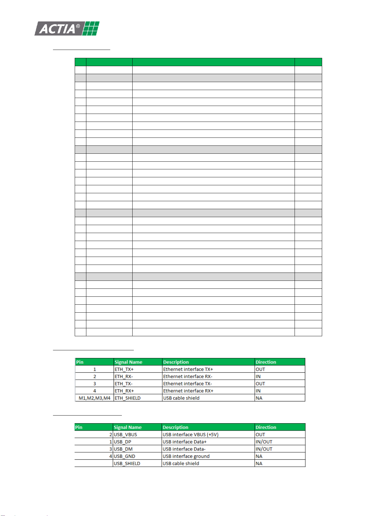
CN2 Ethernet connector pinout:
CN3 USB connector pinout:
P218703
ADt 001 M
B
© 2021 « Any reproduction of this document whether total or partial without the written consent of ACTIA Automotive is forbidden”
Page 16 sur 37
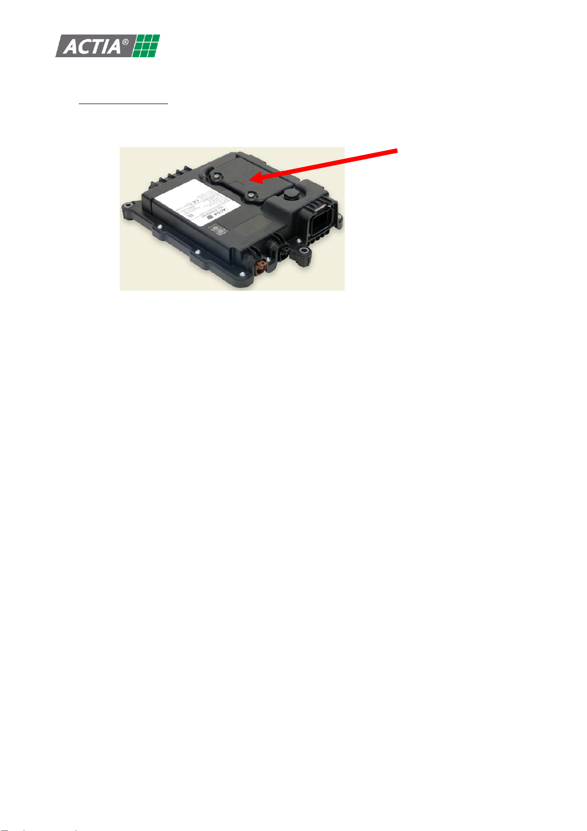
V.2 BATTERY AND SIM CARD
Depending of TGU-R ACCESS variants, a rechargeable, replaceable battery pack is accessible behind a trap door.
Depending of TGU-R ACCESS variant, a SIM card connector or an eSIM is available.
If your product has SIM card connector, you can access to it by opening the trap door and removing the battery pack.
To access SIM card connector and optional battery pack, follow instructions described in VII.10
P218703
ADt 001 M
B
© 2021 « Any reproduction of this document whether total or partial without the written consent of ACTIA Automotive is forbidden”
Page 17 sur 37
VI PRODUCT OPERATION
TGU-R ACCESS shall not be used in environment not compliant to its specification.
User shall check that installation and operating range conditions are inside this user manual and product specification
especially on:
Power supply input range
Operating temperature range
Storage conditions
VI.1 TRANSPORTATION AND STORAGE:
TGU-R ACCESS transportation must be done only using the original packaging.
Before TGU-R ACCESS installation and during transportation, ACTIA recommend to store the product in its original
packaging, in a suitable indoor location with following conditions, to optimize internal battery pack option, RTC coin
cell and other components life duration:
Unit
min
Typ
Max
Conditions
Optimal storage
temperature
before installation and
during transportation
°C
10
20
30
To prevent decrease of battery pack
and coin cell and other components
life duration
Relative Humidity storage
%
40
-
75
Storage duration @above
optimal storage
temperature range
before installation and
during transportation
Year
1
To prevent deep discharged battery
pack (for product variants without
battery pack option, the duration is
limited by RTC coin cell life time : 10
years max )
Also applicable for battery spare part
Recommended min
optional battery pack
charging level
%
30
*
To prevent deep discharge
*Note: Maximum charging level
during transportation shall be set
according to transportation rules
applicable in the countries.
VI.2 HANDLING:
TGU-R ACCESS must be handled with care to avoid excessive shocks and unexpected fall down during handling,
installation or use.
VI.3 SIM CARD:
SIM card operating temperature range shall be chosen by customer to comply with their target application ambient
operating temperature range + 10°C to consider TGU-R internal self-heating:
Examples:
Using standard SIM card with operating temperature range = -20°C to +70°C customer will be limited to
following TGU-R application ambient temperature range = -20°C to +60°C
Using rugged SIM card with operating temperature range = -40°C to +105°C customer will reach full TGU-R
application ambient temperature range = -40°C to +85°C
VI.4 NETWORK OPERATOR:
Network operator shall be selected by customer to comply with their target application needs:
countries coverage according to supported TGU-R frequencies (see §IV.4)
countries regulations (product shall be certified on target countries usage, see §) and some local countries
request the use of local server and SIM card
data exchange quantity
When using AT&T SIM cards, under AT&T request, customer shall provide annually TGU-R product IMEI list
P218703
ADt 001 M
B
© 2021 « Any reproduction of this document whether total or partial without the written consent of ACTIA Automotive is forbidden”
Page 18 sur 37
VII INSTALLATION
VII.1 POWER DISSIPATION:
TGU-R ACCESS shall be mounted in a non-confined area and as far as possible from other power ECUs in the
vehicle to prevent excessive heating and as consequence reduced operating range and accelerated aging.
VII.2 MECHANICAL CONSTRAINTS
Fixation:
The mechanical support of the TGU-R ACCESS must have a surface flatness tolerance of 0.5 /100 mm.
To fix the TGU-R ACCESS, use M6 flat-headed screws with or without a lock washer, with a tightening
torque of max 10 Nm.
Customer installation shall be done according to TGU-R ACCESS interface drawing REF2
Protection index:
ACTIA recommend to install TGU-R ACCESS in the vehicle in the way it is protected against direct water jet
and above vehicle water stream limit even if it complies with P67 and IP6K9K levels.
To keep TGU-R ACCESS waterproof level, sealing cap shall be used on all unconnected connectors using
caps delivered by ACTIA with the product on USB / Ethernet / Fakra connectors. Main connector unused
pins shall have a sealing cap as recommended in product specification [REF1]
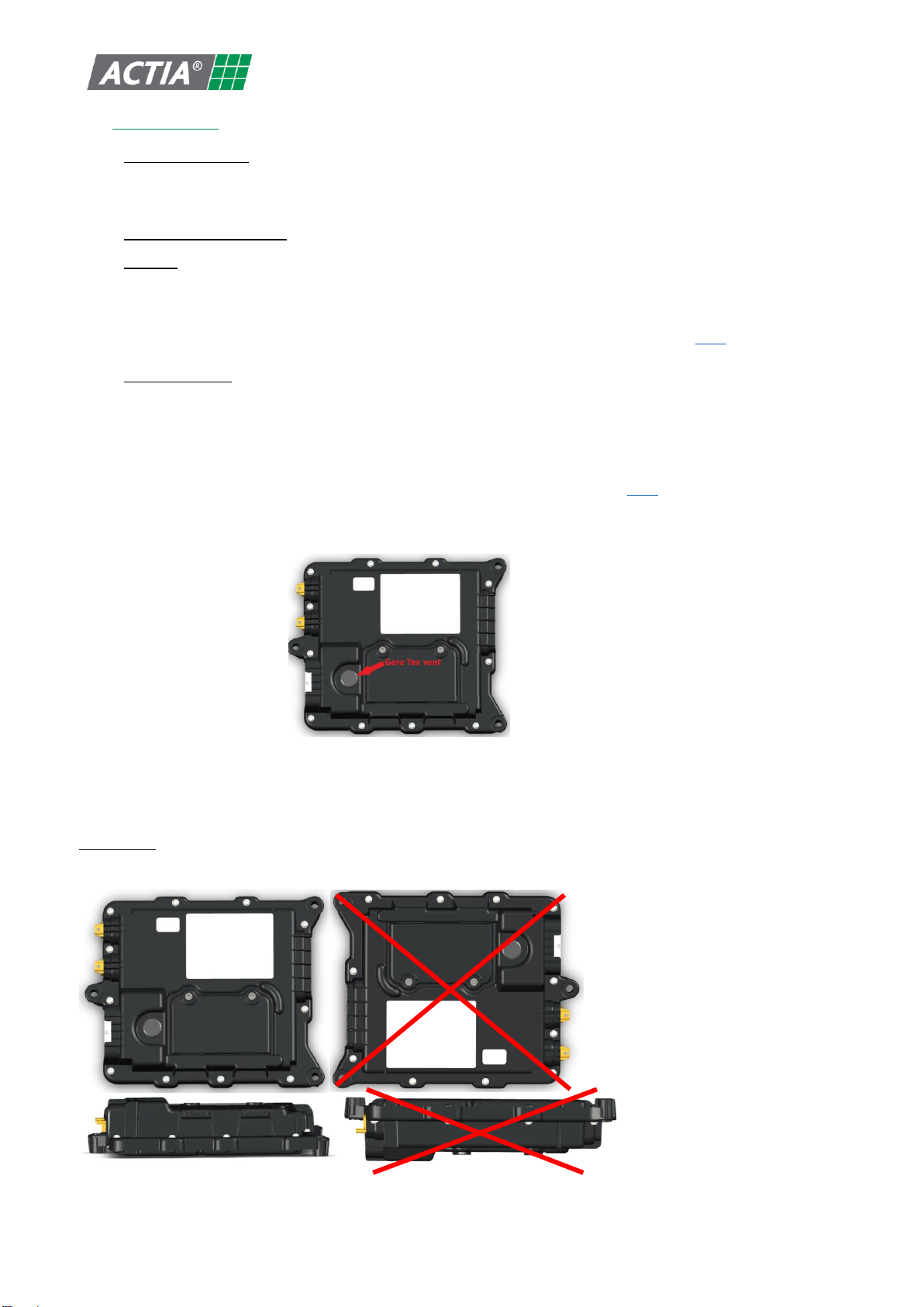
Special care shall be taken to have TGU-R ACCESS Goretex vent always free of water and dust to operate
and regulate humidity and pressure inside the product.
TGU-R ACCESS shall be installed in restricted access locations to prevent:
Direct UV radiation, gravel projections, corrosion
Hacking, theft, intentional damage
Orientation:
We recommend following positioning to avoid water and dust accumulation.
The 2 TGU-R ACCESS LEDs shall remain visible for easy diagnostics during maintenance operation.
P218703
ADt 001 M
B
© 2021 « Any reproduction of this document whether total or partial without the written consent of ACTIA Automotive is forbidden”
Page 19 sur 37
VII.3 CONNECTORS AND WIRING :
All matting plugs used to connect TGU-R ACCESS shall be according to the references stated in product
specification REF1 and operated according to supplier instructions to avoid connector stress, bad electrical
contact, corrosion, loss of waterproof level.
Cables fixations : All cables connected to the TGU-R ACCESS shall be tied between 10cm and 15cm from the
product connector, and on the connector axis to avoid mechanical stress on connectors and plugs.
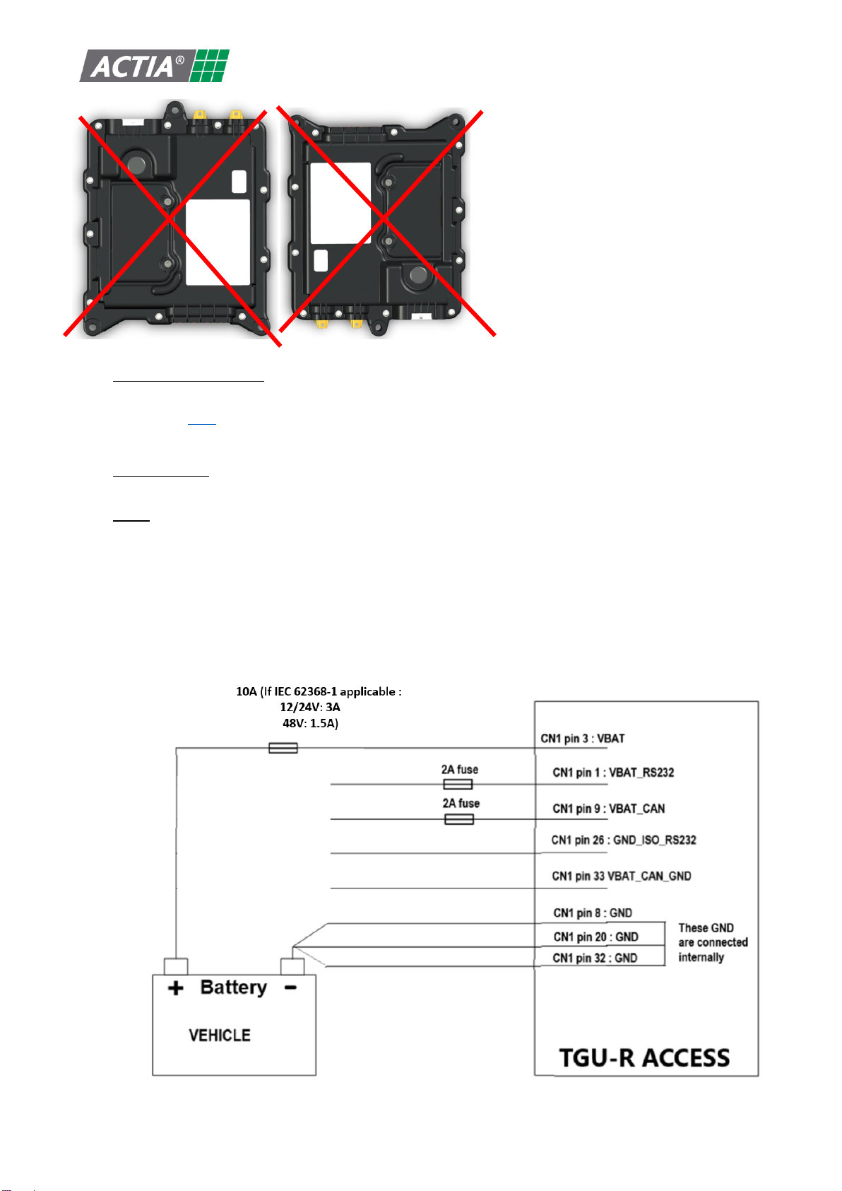
VII.4 FUSES:
No fuses are enclosed in the product. Thus an external protective fuse shall be installed outside of the unit,
between the vehicle battery and the product VBAT power supply input.
12/24V vehicle battery system: 10A (shall be 3A if IEC 62368-1 applicable)
48V vehicle battery system: 10A (shall be 1.5A if IEC 62368-1 applicable with min operating voltage range
at 16V instead of 6V)
An external 2A fuse shall be installed on VBAT_CAN and VBAT_RS232 lines when isolated CAN and/or isolated
RS232 interfaces options are used.
P218703
ADt 001 M
B
© 2021 « Any reproduction of this document whether total or partial without the written consent of ACTIA Automotive is forbidden”
Page 20 sur 37
VII.5 CAN LINES
General:
CAN wiring lines must withstand the following constraints:
We recommend to twist CANH, CANL lines to avoid EMC issues. The wire section must be at least 0,5
mm².
It is possible to twist a ground wire with CANH and CANL.
CAN lines layout:
The CAN lines must not be placed near disturbing cables such as:
Power cables (DC/DC converters)
Cables connected to loads driven in PWM mode
The CAN line must be as short as possible. The loops on the CAN line must be avoided.
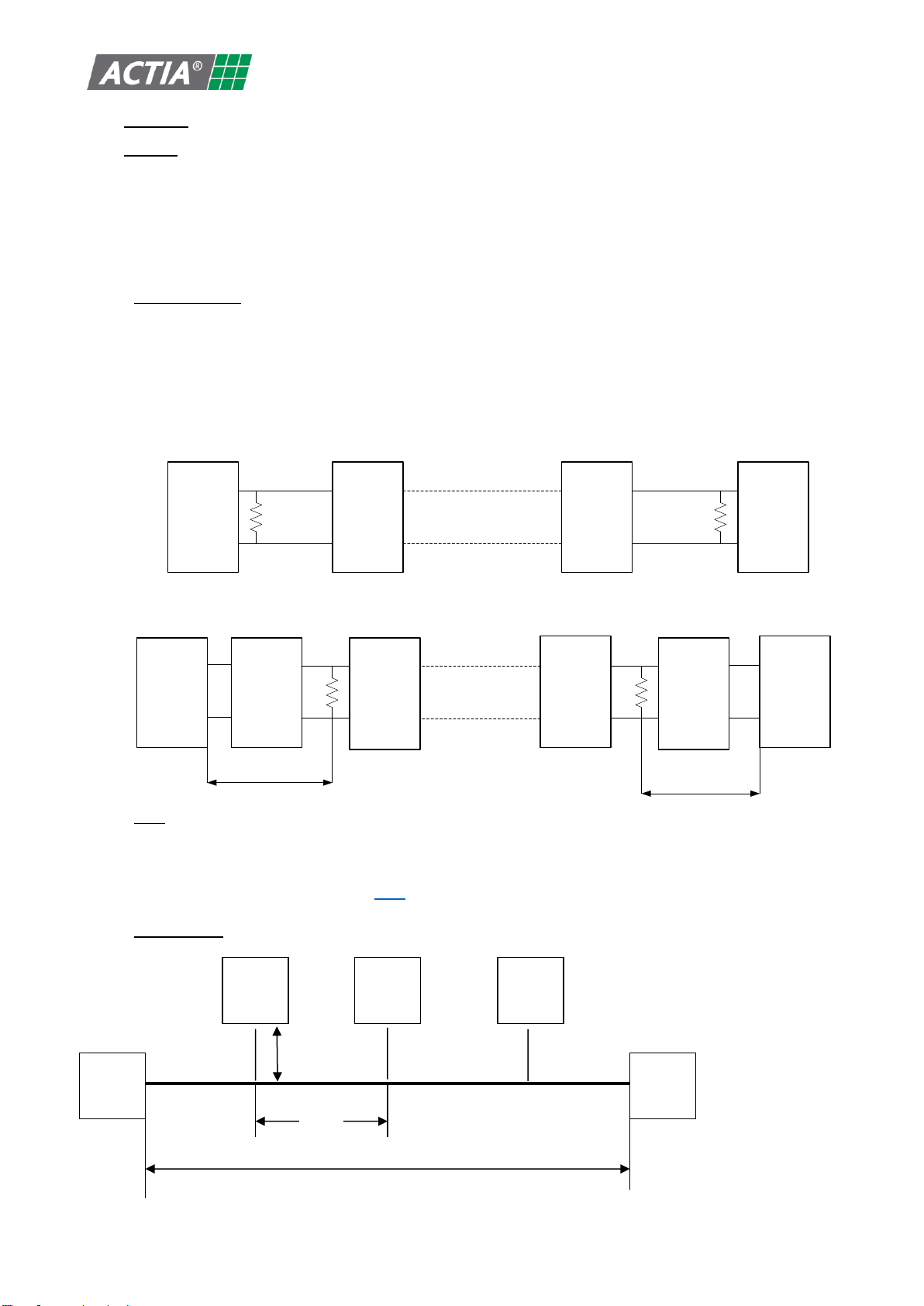
Two 120 resistors must be placed at each bus termination:
ECU ECU ECU ECU
120 Ohm 120 Ohm
The following topology can be also used, when it is not possible to use the previous one:
ECU ECU ECU ECU
ECU ECU
120 Ohm
120 Ohm
1 m 1 m
Note: each rectangle represents an ECU. Depending on ECU version, the 120internal resistor can be always
present or selectable by external wiring: see each ECU data sheet.
If TGU-R ACCESS is acting as CAN termination node, CAN strap option could be done via CN1 wire harness, see
product specification for more details REF1.
Wiring layout:
ECU 1
ECU 2
ECU 3
ECU n
- 1
ECU n
L
d
w
Table of contents
Other Actia Automobile Accessories manuals

Popular Automobile Accessories manuals by other brands

Soundoff Signal
Soundoff Signal mpower Fascia 4 quick start guide

Thule
Thule RAPID SYSTEM 1213 Fitting instructions

aci
aci ADARAC Aluminum M Series installation instructions

Metra Electronics
Metra Electronics 99-3400 installation instructions

Lippert Components
Lippert Components X-Trek installation manual

Dometic
Dometic COOLAIR RT780 installation manual


