Action CARISBROOKE Manual

Technical Information:
Number of people required for assembly: 2 to include a good handyman
Guide time for assembly: approx 8-10 hours for the full unit
The Carisbrooke needs 7 bags of instant mix concrete (post-Crete) or similar allowing 1/2 bag per
hole. (available from most hardware shops or builders merchants)
NOTE: USE THE DRILL BIT PROVIDED TO PRE-DRILL ALL THE SCREW HOLES TO AVOID SPLITTING THE
TIMBER. You may want to use a countersink drill bit to give the screw holes a superior finish
Your climbing frame can be stored outside until you are ready to assemble the unit, we recommend
storing it near the place you are looking to build it.
To allow trapped moisture to evaporate cut back the shrink wrap packaging but be careful not to
lose any parts. Slight cracks may appear in the wood at any time after delivery, this is due to the
natural working of the wood and is normal. If moisture is trapped under the plastic you will
sometimes find mould spots present, this will wipe away and have no long term effects.
NB: Cracking will not affect the tower's structural stability. Surfaces of the wood have been planed
but you may find small splinters around drill holes which can easily be sanded away.
Contents: Packs Required:
1) Construct the Tower JE2051/1 (x2)
JE2090/2 (x2)
JE2090/3 (x2)
JE2058 (sandpit)
2) Attach the Tunnel JE2108/1
JE2108/2
JE2108/3
3) Attach the Staircase JE2057/1
JE2057/2
4) Attach the Ramp JE2055
5) Attach the Swing beam JE2550
6) Attach the Assault Course JE2556/1
JE2556/2

7) Attach the slide JE2515
8) Attach the swing seats (boxed separately)
Where to start: Firstly dig the holes for the uprights
Lay your platform base on the ground at the chosen position. Using a spirit level find the highest
corner, this will be your first hole. If the difference in height between one side of the platform and
the other is greater than 75mm you should level off the ground or consider moving your frame to a
more level place in the garden.
Take a 50mm slice of lawn and put it to one side for return later. Dig the first hole to 300mm deep
and about 300mm square. (a useful note is to place the removed soil on to a plastic sheet to
minimise clearing up afterwards) Move on to digging the next hole - use the tip below for getting the
holes level. Once you have dug the corner holes then dig the final hole for the front central upright
in the same way.
TIP: Digging all the holes to be level involves a simple trick using 2 equal balustrade pieces and a
spirit level. Stand one balustrade upright in your first (measured) hole and the second upright in the
next hole. Place your spirit level on top of these two pieces (if your level is not long enough then
please use a straight piece of wood rested on top of the balustrades and then put the level on top of
this). Adjust the depth of the second hole either by further digging or adding back some soil until
your spirit level reads correctly. Once this hole is complete do the same to the other holes in turn.
Always use the first hole as the reference point. When finished NO hole should be less than 300mm
deep, if it is your ground is too steep and you need to level off the platform area. The reason for this

is that your slide needs to be on a platform 1.5m (or 1.2m with some models)above the ground. If
the height is more or less than this creates stress on the slide platform mount and in severe cases
can lead to fracture of the slide at this point. A failure that would not be covered by warranty.
You may also find this video link helpful showing you how to prepare the holes:
http://www.youtube.com/watch?v=bDqh-mwi0w8
Construct the Tower:
Attach the floor to the uprights this is best done with the frame laying on its side. Lay the uprights in
pairs with their ends close to the holes you have prepared. Align the platform in the same direction
as the slide will end up when you have finished, this then orients the uprights and their bolt holes.
The platform bolts pass through the holes closest to the ground. The holes slightly higher up are for
mounting accessories.
Stand the platform upright and bolt the platform to the tow uprights lying on the ground. Repeat
with the other two uprights with one end resting on the ground and the other ends pointing towards
the sky. Tighten the bolts firmly but at this stage do not overdo the tightness.
Building the Balustrades:
Pre-build your balustrades on the ground as squarely as possible rather than trying to build them on
the tower frames. You will notice in the drawing that the screws are diagonally offset. The purpose
of this is to reduce splits and create a stronger fixing, by not having screws running in a line along the
grain of the wood. You may want to pre-drill all your timbers in advance. To generate a neat

appearance try to drill in the same place on each piece. Select one piece of part C and drill the screw
holes as shown in the diagram.
Attaching the Sandpit:
Pre-drill the sandpit sides Parts A 30mm from each end and central Mark with a pencil 35cm from
the lower end of your uprights and attach four sandpit sides flush with these marks, using screws (1).
Add the second and third layers above the one already fitted. Ensure the frame is square before
fitting the seats (parts B) with 2 x 60mm screws (1) at each end.
Use the bit provided to pre-drill all screw holes to avoid splitting the timber. It will speed up progress
if you pre-drill all your timbers before you start building.

Attaching the Ladder:
Attach parts H to I to make up the ladder. This can now be attached to part J which in turn is
attached to the tower uprights.
Components and Hardware:
12 x (A) 30x65/89.5cm
2 x (B) 20x120/52cm
32 x (1) 5x60mm

Attaching the roof:
Fix the roof trusses to the frame uprights using the 60mm
screws. 2 screws to each upright. The bottom of the truss
should be 75mm down from the top of the upright.
Please ensure the uprights are parallel and the truss has the
same overhang.

Then fix the roof slats (part E) to the trusses, using the 60mm screws. 1 at each end. Ensure the slats
have the same overhang and the trusses remain parallel
Raising the Tower:
Once you have built the tower it is time to lift it into place. We recommend using 2 people to do this
part. Firstly move it to gently line up with the leading two holes, then each takes a lower corner and
gently lifts up/walks under the tower until it is vertical. It usually slides into the prepared holes quite
easily. At this stage check the tower platform for level in both horizontal directions and the uprights
are vertical. Tighten the platform nuts firmly but not to the point of breaking the wood. Once you
are satisfied with your spirit level readings you can proceed with construction. Once you have
completed the build of the first tower, use the dimensions from page 6, to locate the position of the
second tower. Build the second tower using the instructions you have followed to date. Measure the
spacing between the towers.
Components & Hardware:
20 x (E) 1/207/100cm
2 x (F) Roof
48 x (4) 5 x 60mm

You will now need to fit the two Tunnel frames (parts C) one to each tower. Only build the tunnel
sufficiently to locate the 2nd tower and check all sides are level and upright. Once you are satisfied
that the second tower uprights are vertical in both planes (using your spirit level) and the platform
horizontal, proceed with construction. (if you are planning on taking a break at this point you may
consider concreting (Post-Crete) the towers.
TIP: To align both towers in as straight a line as possible build as above then before concreting stand
back as far as you can to get a view of the four uprights on one side. Move the 2nd tower as needed
until all four uprights are lined up.
*Now repeat for the second tower*
Attaching the Tunnel:

Ideally make the tunnel frame up on the floor.. although be aware two people will be required to lift
up onto the two towers. Fix the boards to the tunnel ends using the 45mm screws.
The wider boards are fixed to the top, bottom and sides. The side boards are fixed with 1 x
80mm and 1 x 45mm screw at each end. The smaller boards are fixed on the 4 corner faces.
The 30mm x 65mm rail will need to be re-positioned. It should be 7cm above the tunnel.

Attaching the Staircase:
You will need 1 bag of Post-Crete (already mentioned earlier) for concreting the bottom of
the stairs and handrail posts. You will find it easier to only fit the top, middle and bottom tread to
the stair string at first. When you have fitted the handrails and posts , at the end of this section you
can then finish fitting the remaining treads, This makes the staircase lighter to lift wile fitting to the
tower.
You are now ready to fit the staircase. You have two more holes to dig for the bottom of the
stairs and the handrail posts. Follow the dimensions on the following pages. If the sides of the stairs
are going into the ground by more that 300mm you may wish to cut the excess off. Ensure you cust
the bottom and NOT the top of the stairs. Pile your soil onto a piece of plastic to minimise clearing
up afterwards.

Staircase components:
To achieve a neat appearance, pre-drill the two staircase sides B & B' from the Inside (tread side).
Cut a piece of paper or card to the exact shape of the tread slot and mark 2 holes 3cm from either
end along the centre-line of the slot. Use this piece of card as a template to drill all the holes in the
same place for each tread.

Fit three treads to start with as it will make it easier to move the staircase around while construction
is continuing. Fix the treads using (part1) 5 x 60mm screws. Stand the staircase up against the tower
ensuring the treads are level (from back to front and sideways). Measure down from the top tread to
the top of the platform. This will tell you how deep the hole will need to be for the bottom of the
stairs. The top tread will need to be level with the platform when in its final position. Attach the stair
string (part B) to the tower uprights (parts X) using 4 x 5x80mm screws (part 2). Fix the posts (part D)
also using 4 x 5x80mm screws (part 2). Ensure the posts are upright before fixing. Fix the hand rail
flush with the top of the post (part D) and flush with the inside edge of the tower upright (part X).
When fitting the handrails ensure they are parallel with the stair strings (sides). The height of the
handrail will be governed by the depth of the bottom holes but, the holes should be no more than
300mm deep. Now fit the rail (part C from P4) to the tower uprights (part X). It should sit tight to the
underside of the stair strings. Fix using 4 x 5x60mm (part 1). Now screw through from the back of
this rail into both stair strings using 2 x 5x80mm (part 2). (See picture top right)

Attaching the Assault Course & Swing Beam:
you will need 2 bags of Post-Crete (already mentioned earlier) for concreting the bottom of the
swing beam supports and the Assault Course supports. You may find it easier to attach the swing
hooks while the beam is still on the ground rather than struggling up a ladder. Please note only fit 4
swing hooks. You will need to refer to the Assault Course instructions as well to ensure the supports
are the correct way round and the right measurement in from the end.
You are now ready to construct the swing beam and supports. Dig the holes for the supports using
the dimensions on the following page. The holes will need to be approximately 30cm square and
30cm deep. Take a 5cm slice of lawn and put to one side for return later. Pile your soil onto a piece
of plastic to minimise clearing up afterwards.

ATTENTION: Allow a minimum of 2 metres space around the Playcentre and ensure that the area is
free from other obstacles such as trees and branches, garden lights and other play equipment.

To make up the A-Frame, use the 130mm bolt, nut and washer and push through both part A's. The
nut and washer will sit in the recess around the bolt hole. The spread the legs out so, the
measurement from outside to outside of the part A's is 255cm. The drill two holes at each end of
Part C approx 30mm in. Fix using 4x60mm screws. This rail should be flush with both sides of parts A
and the same distance up from the bottom of Part A.

Push the swing hooks through the pre-drilled holes in the swing beam (B), and secure using 1 x m10
washer and 2 M10 nuts. The second nut acts as a locking nut. Ensure the swing hook is at right
angles to the beam, as shown in the picture above.
Then attach the swing beam (part B) to your desired upright (X) of the tower, using (Part 5) 10 x
150mm bolt, M10 nut and M10 washer. The nut and washer should sit in the recessed hole as shown
in the diagram above.
Two people are needed for this next bit. Lift the A frame into the previously dug holes. One person
holds this in place. The other person lifts up the swing beam (part B) above the height of the A
frame. Then slowly lower the beam so it sits in between both parts A.
Now check that the beam is level and adjust the height by either digging the holes deeper or adding
soil to the hole.
Make sure the A frame is upright and approximately 100cm in from the end of the beam, before
continuing.
Components & Hardware:
1 x (B) 9x9/360cm
2 x (D) 30x65/40cm
6 x (2) M10 washers
11 x (3) M10 nuts
6 x (4) 5x60mm screws
1 x (5) 10x150mm bolts
2 x (6) 6x120mm screws
5 x (7) Hook

TIP: When you come to build the swing arm we suggest you first drill a 4mm pilot hole in the two
uprights A before attaching the swing arm beam B with the two 6x120mm screws.
Attaching the Assault Course:

Assault course hardware list:
We strongly suggest that you pre-drill all holes before fixing screws. This will prevent the screw
splitting the wood.

ATTENTION: Allow a minimum of 2 metres space around the Playcentre and ensure that the area is
free from any other obstacles such as trees and branches, garden lights and other play equipment.

Before you fix the swing beam to the supports you will need to attach the Assault Course net.
Do not tighten the ropes fully until the A-Frame is in place.
Table of contents
Other Action Outdoor Furnishing manuals
Popular Outdoor Furnishing manuals by other brands
New England Arbors
New England Arbors ups Bordeaux Assembly guide
kingsley-bate
kingsley-bate PV-50 Assembly instructions
Costco
Costco 1142647 Assembly / care & use instructions
U-Line
U-Line H-5181 Installation
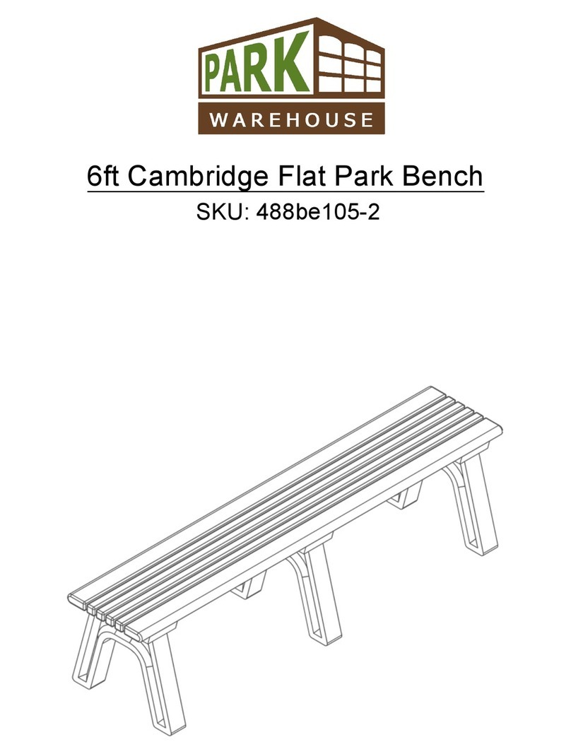
PARK WAREHOUSE
PARK WAREHOUSE 488be105-2 quick start guide

Happy Garden
Happy Garden SAULE STO04 manual
