Active Design CAPS II User manual
INS150 Version 1
1
November 2018
CAPS II User Guide

INS150 Version 1
2
November 2018
Who to contact for support
If you have a problem with any of our products, your first contact should the
organisation who supplied the product to you. If there is a problem that your
therapist is unable to answer then please do get in touch directly.
Your Seat Details
Serial number label here

INS150 Version 1
3
November 2018
Table of Contents
1Your seating system ......................................................................................... 4
2Using the seating system ................................................................................. 7
3Seat Options................................................................................................... 15
4Identifying when adjustment is needed ........................................................ 20
5Transportation ............................................................................................... 24
6Routine Maintenance .................................................................................... 27
7Important Information................................................................................... 29
Parts included in this CAPS II Seating System
Seat Unit
Pommel or kneeblock
Footrests
Headrest
Harness
Lap Belt
Tray
Interface Board

INS150 Version 1
4
November 2018
1
Your seating system
This User Guide will help you to get the most from your seating system – please
take some time to read the relevant sections carefully!
We work hard to bring the best evidence-based products to market using the latest
manufacturing techniques. We work as a multi-disciplinary team to develop our
products, and have a highly skilled manufacturing unit to manufacture our designs
in the UK.
Training, support and customer service are a key part of what we do to help to
ensure you get the most from your seating system and it meets your postural and
lifestyle needs.
All of our products are developed with durability in mind.
INS150 Version 1
5
November 2018
1.1
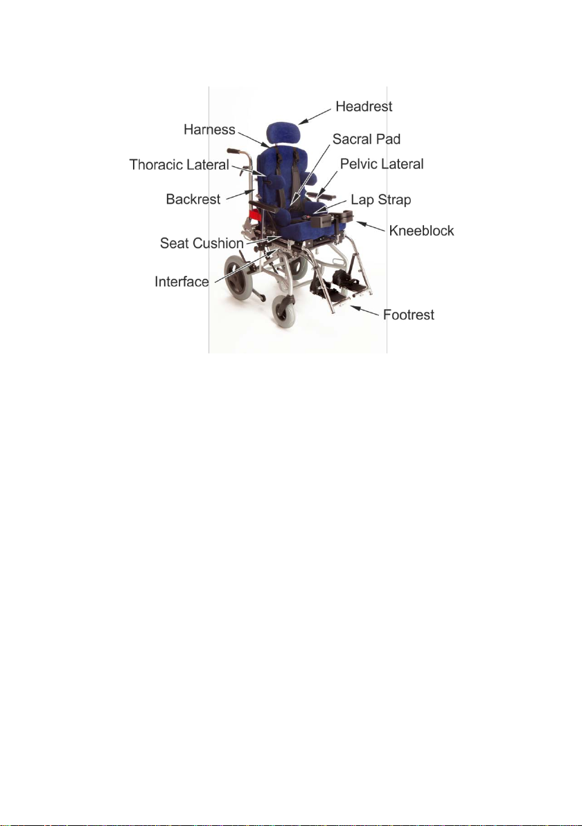
Identifying parts of the seating system
•Backrest – Provides a solid base with a cushion to support the back
•Headrest – Supports the head
•Thoracic Lateral – Supports the top part of the body (the trunk). May be
set to work with the Pelvic Laterals to correct or prevent curvature of the
spine
•Pelvic Lateral – Support the sides of the pelvis. Work with the Lap Strap
to keep the pelvis in a good position. Work with the Thoracic Laterals to
correct a curvature of the spine. May work with a kneeblock to align
asymmetrical legs
•Kneeblock – Works with the Sacral Pad and Lap Strap to keep the pelvis in
an upright position
•Footrest – To position the feet. Will work with the seat cushion to help
distribute pressure. May work with the kneeblock or pommel to align the
legs
•Harness – Help to position and stabilise the top part of the body.
•Interface – Allows the seat to be attached to and removed from the
wheelbase.
•Sacral Pad – Support the back of the pelvis and works with the lap strap
and kneeblock to keep the pelvis upright
•Seat Cushion – Supports the bottom of the pelvis and the legs. It normally
has a ramp to keep the legs in a good position.
•Lap Strap – Works with the Sacral Pad and Lap Strap to keep the pelvis in
an upright position

INS150 Version 1
6
November 2018
1.2
Seat configuration
The seating system will be delivered already set up to the measurements recorded
during the assessment. If measurements were not provided when the seat was
ordered, the chair should be pre-set by the clinician at the seating clinic before the
user is positioned in it.
Your seating system should be already set up and adjusted by a qualified
prescriber. Clinical suitability and stability of the seating system should also be
checked at delivery.
If the wheelbase is a tilting type, you may find it useful to tilt the base when
positioning the user in the seating system. This will help to position the pelvis back
against the backrest with the help of gravity.
With the user in the seat, it is a good idea to check the supportive components in a
methodical way. Start by ensuring the pelvis is adequately supported, and then
work towards the feet. Afterwards, work upwards from the pelvis. We suggest this
order:
1. Pelvis back against back cushion and pelvic strap in place
2. Knees in position
3. Feet in position on the footrest and footstraps attached
4. Trunk harness in place if used
5. Head in position on the headrest.
If you had tilted the seat for the transfer, reduce the tilt to the appropriate
position.
It is important to check the seat, particularly the adjustable parts, during the first
few weeks of use. Most importantly, check the effect the seat has when it is first
delivered. Tell the fitting team if you have any cause for concern, e.g. if the person
has very red knees or a sore bottom, or if they do not even want to use the seat.
The seat will be providing a new posture for the user to learn. Try to avoid
introducing other new things at the same time! Do not let them sit in it for too long
when they are just getting used to it. Check with your therapist if you are unsure
how long to expect them to use the seat at first.
Small adjustments, by the seating team, may be necessary during the first few
weeks or so, as the user becomes accustomed to the seat.
After initial set-up adjustments are made, you should check the seat daily for fabric
wear and to check all the parts are operating to a good standard.

INS150 Version 1
7
November 2018
2
Using the seating system
The CAPS II Seating system has been specifically designed to meet demanding
postural requirements, whilst being very adjustable, adaptable and easy to use.
The following information is intended for general use of your seating system that
are appropriate for all users. Adjustments to the seating system not outlined in this
manual should be completed by a competent Therapist or Rehabilitation Engineer.
There are many options available with the CAPS II seat to ensure an appropriate
posture is maintained. Please read the appropriate sections based upon the seat
you have been provided. If you are unsure, please check with your prescriber.
Many of the parts are removable from the wheelbase to make handling it easier.
Some parts are fixed and not removable. When the seating system is handed over
to you, this should be demonstrated to you.
You should also read carefully the user manual provided for the wheelchair.
The seating system can be removed from the wheelbase to enable it to be used on
a second wheelbase. To reduce the weight of the seat unit, first take out the
removable components.
INS150 Version 1
8
November 2018
2.1
Headrest
1
To remove the headrest,
rotate the lever to release the
headrest
2
Slide the headrest out of the socket.
To replace the headrest, slide it back into the receiver. A sleeve tube on the
headrest stem should ensure it is positioned in the same location each time.
Tighten the lever by turning it clockwise.
INS150 Version 1
9
November 2018
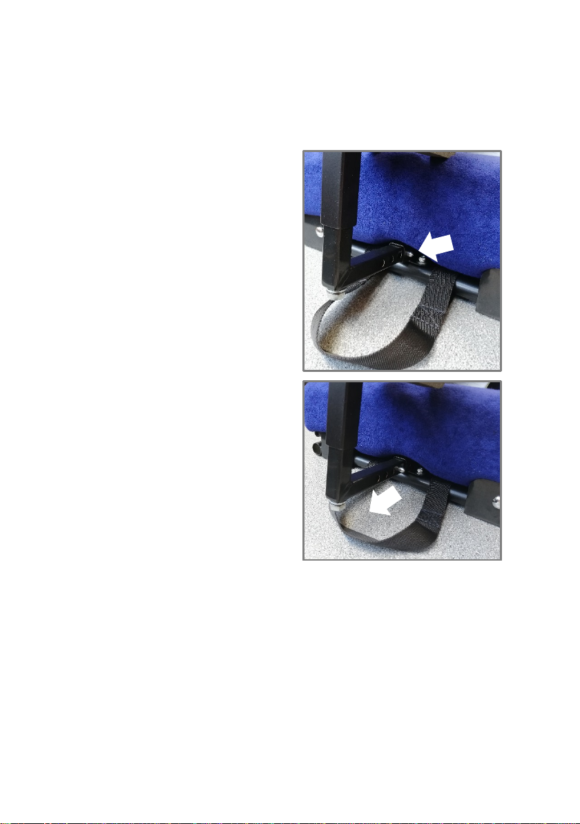
2.2
Footrest
1
To remove the footrest, push
the pip pin located at the front
of the seat
2
Pull the footrest drop towards
you.
On some footrest types, like a padded footbox, both footrest drop tubes are linked
together. If this is the case, you will need to release one side slightly, release the
opposite to allow the complete footrest to be removed.
When replacing the footrests, ensure they are fully locked into position and the
footstraps attached where required.
To replace the footrest, push the pip pin and locate the footrest drop tube in the
receiver. Ensure it clips into place.
INS150 Version 1
10
November 2018
2.3
Pommel or Kneeblock
If your system comes with a knee block or pommel you can remove it and adjust
the height and depth. To remove press the release pin, located on the pommel
mounting bracket underneath the seat, and pull the pommel out.
1
Press the release pin
underneath the front of the
seat.
2
Pull the pommel or kneeblock
towards you.

INS150 Version 1
11
November 2018
2.4
Straps
The pelvic strap and harness should be clipped into position and tightened. When
the seating system is handed over, you should be shown how tight it should be. If
the user is hoisted into the seating system, the straps should be attached before
removing the hoist and sling.
Before clipping the straps together, do a quick check to ensure the webbing is not
twisted or caught.
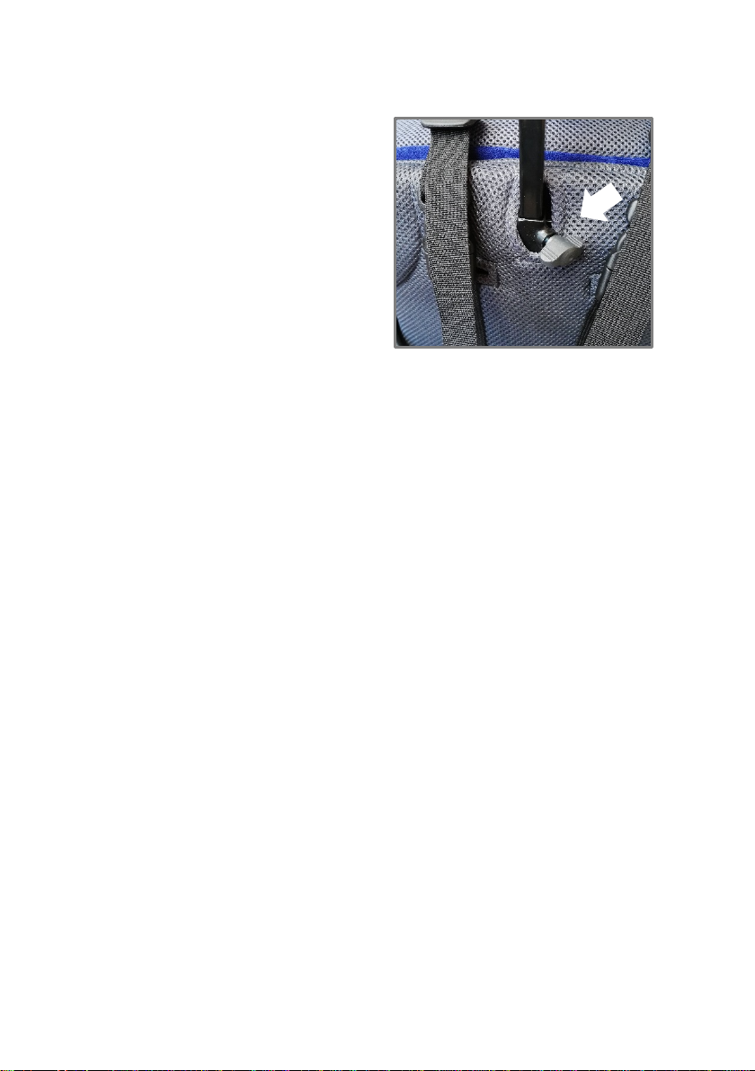
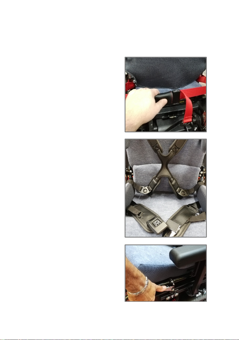
Different types of harness are used on the seating system. Both the Top Pull and
Rear Pull Harnesses are tightened from the rear. The Front Pull harness is tightened
from the front.
1
Rear Pull Harness
Tension is adjusted by pulling
the webbing loop towards the
rear of the seat.
2
Front Pull Harness
Tension is adjusted by pulling
the webbing loop towards the
front of the seat.
3
Top Pull Harness
Tension is adjusted by pulling
the webbing upwards.
INS150 Version 1
12
November 2018
2.5
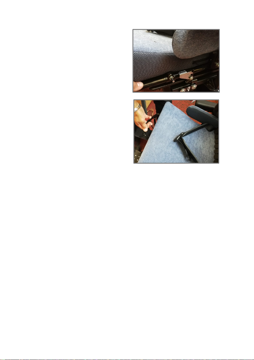
Removing the seat unit
The seat unit should only be released and removed once the user has transferred
out of the seat.
1
Disengage the rear red seat
retaining strap and clip back
into place next to the
backrest. Pull it as tight as you
can so it does not hang down
during removal of the seat.
2
Place any loose straps onto
the seat base so they don’t get
in the way.
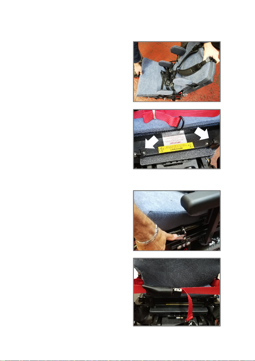
3
Disengage the two catches,
one on each side of the
seating system.
INS150 Version 1
13
November 2018
4
Holding the front of the seat,
lift it out of the catch and put
the front of the seat back
down just in front of the
catch.
5
Standing at the side, hold the
front carry handle and the
rear of the seat, lift the seat
unit off the interface board.
INS150 Version 1
14
November 2018
2.6
Attaching the seat unit
1
Standing at the side, hold the
front carry handle and the
rear of the seat, lift the seat
unit. Take care when lifting a
heavy weight.
2
Engage the pins at the rear of
the interface board into the
holes on the rear of the
seating system
3
Fully slide the seat unit back into place
4
Locate the pins at the front of
the interface board into the
catch and ensure they fully
engage.
5
Secure the red seat retaining
strap around the push handles
of the wheelchair.
INS150 Version 1
15
November 2018
3
Seat Options
The seating system may be supplied in one of a number of configurations with
several possible options fitted. If you have any of these fitted to your seat, the
clinician will let you know when the seat is handed over to you.
3.1
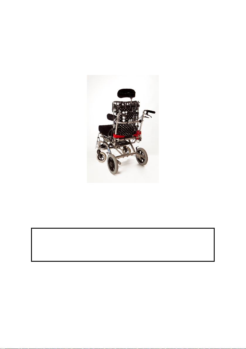
Lynx Backrest
A Lynx Seating System has a special backrest whose shape can be changed over
time. This can be to accommodate changes in posture. It consists of a number of
interlinked plastic components. This will typically be fitted to the backrest of the
seating system. The seat in the photo above is shown with the backrest covers and
cushion removed.
!
The Lynx backrest is not user adjustable. Please
refer to your clinician if you feel adjustment of
modification may be required.
INS150 Version 1
16
November 2018
3.2
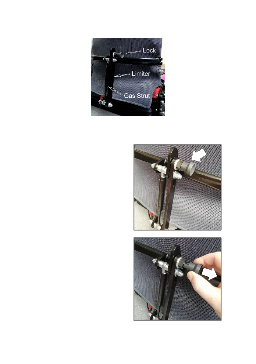
Dynamic Backrest
A Dynamic Backrest allows the backrest to move if the user extends heavily and
may be supplied after careful consideration by the clinicians.
1
The Lock is shown in the
Locked position.
2
Disengage the lock to allow
the dynamic backrest to
move. Pull the Lock towards
you and rotate it a quarter of
a turn.

INS150 Version 1
17
November 2018
The backrest pivots with a Gas Strut controlling how easy it is to push. A Limiter
limits the range of movement. The Lock enables the dynamic element to be
removed when it is not required or should not be used, such as during transport.
!
The Dynamic Backrest must be locked when used
in transport.
INS150 Version 1
18
November 2018
3.3
Swingaway Lateral Supports
Swingaway Lateral Supports may be fitted to the seating system to make transfers
into and out of the seat easier. They can be fitted to one or both sides. There are
two types of swingaway lateral supports. You may need to move the backjacket
cover to see the type of swingaway that has been fitted.
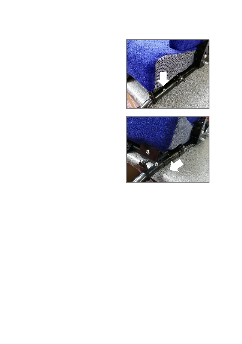
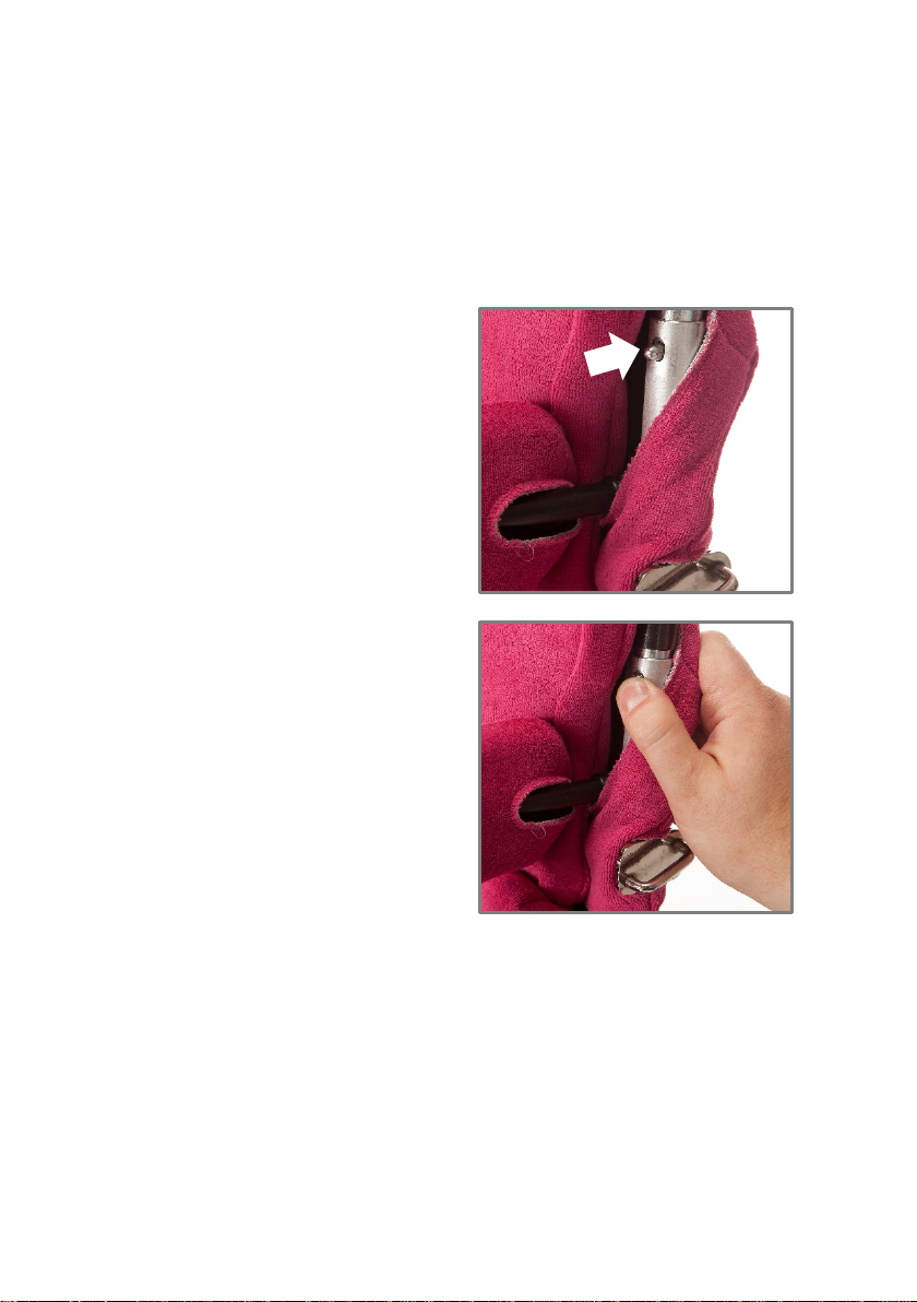
3.3.1
Sleeve Tube Type
1
Locate the position of the
spring pin that locates the
swingaway lateral support.
2
Press the pin to disengage the
swingaway lateral support.
Swing the lateral support
away to the required position.
3
To lock the swingaway lateral support into position, rotate back around the
tube and ensure the spring pin fully engages.

INS150 Version 1
19
November 2018
3.3.2
Castellated Type
1
Locate the swingaway lateral
support mechanism.
2
Lift the lateral support using
the black tube attached to the
pad. Lift it near the swingaway
mechanism.
3
Rotate the tube away around
the backrest tube.

INS150 Version 1
20
November 2018
4
Identifying when adjustment is needed
It is important to understand when the seat may need adjustment. Adjustment
should only be carried out by your seating team or a competent person.
4.1
Seat depth
The seat depth may be too short if the back of the user’s legs touch the front of the
seat cushion when their pelvis is fully back against the back cushion.
The seat depth may be too long if there is a gap of more than 2” between the back
of the user’s legs and the front of the seat cushion when their pelvis if fully back
against the seat cushion.
4.2
Footrests
The footrests may be too high if the there is a gap between the underneath of the
user’s leg and the top of the seat cushion, or the legs are not parallel to the base of
the seat cushion.
The footrests may be too low if the feet do not make contact with the footrests.
4.3
Lateral supports
The top and bottom lateral supports should be aligned so that the client can be
positioned with their regular clothing.
The laterals may be too close together if it is difficult to fit the user between them.
The laterals may be too far apart if the user leans to one side.
The top laterals may be too high if they are touching the user’s armpit. There
should normally be a gap of between 1” and 2”.
The laterals may be too low if the gap between the top of the lateral pad is bigger
than 2”. Very occasionally thoracic laterals may be set lower for someone who has
good trunk ability, for example of help facilitate self-propulsion on a manual
wheelchair.
Table of contents
Other Active Design Medical Equipment manuals

Popular Medical Equipment manuals by other brands


Getinge
Getinge Arjohuntleigh Nimbus 3 Professional Instructions for use

Mettler Electronics
Mettler Electronics Sonicator 730 Maintenance manual

Pressalit Care
Pressalit Care R1100 Mounting instruction

Denas MS
Denas MS DENAS-T operating manual

bort medical
bort medical ActiveColor quick guide

AccuVein
AccuVein AV400 user manual


