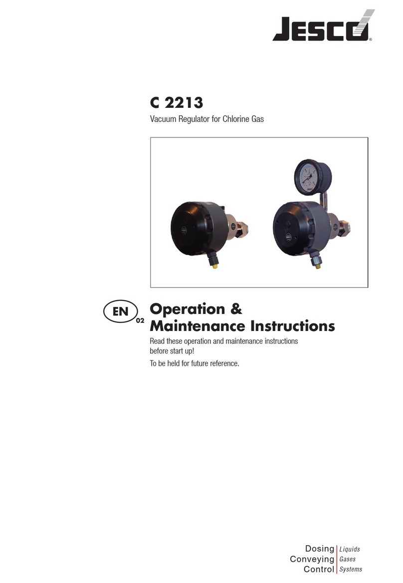
Jesco C 2214 Instruction Manual

C 2214
Vacuum Regulator for Chlorine Gas
Operation &
Maintenance Instructions
Read these operation and maintenance instructions
before start up!
To be held for future reference.
Dosing
Conveying
Control
Liquids
Gases
Systems
EN 02

2 | Operation Manual C 2214 |
Table of Contents
1 Safety ..................................................................................................................................................................... 3
1.1 General........................................................................................................................................................................................................... 3
1.2 Warnings used in this Operation & Maintenance Manual............................................................................................................................... 3
1.3 Qualification and training of personnel........................................................................................................................................................... 3
1.4 Hazards due to non-compliance with the safety instructions ......................................................................................................................... 4
1.5 Safe operation ................................................................................................................................................................................................ 4
1.6 Safety instructions for the owner/operator...................................................................................................................................................... 4
1.7 Safety instructions for installation, maintenance and inspection..................................................................................................................... 4
1.8 Unauthorized modification and production of spare parts .............................................................................................................................. 4
1.9 Impermissible modes of operation ................................................................................................................................................................. 4
1.10 Dosing of Chemicals.................................................................................................................................................................................... 5
1.11 Special notes for working with chlorine gas metering units and the usage of chlorine ................................................................................. 6
2 Before placing in operation................................................................................................................................... 7
2.1 Compliant use................................................................................................................................................................................................ 7
2.2 Scope of delivery............................................................................................................................................................................................ 7
2.3 Steps to take for start-up ................................................................................................................................................................................ 7
3 Functional principle of the vacuum regulator...................................................................................................... 8
3.1 Chlorine Gas .................................................................................................................................................................................................. 8
3.2 Vacuum regulator ........................................................................................................................................................................................... 8
3.3 Technical data................................................................................................................................................................................................. 10
3.4 Dimensions.................................................................................................................................................................................................... 11
4 General................................................................................................................................................................... 12
5 Installation............................................................................................................................................................. 13
5.1 Chlorine delivery............................................................................................................................................................................................ 13
5.2 Design of the piping system........................................................................................................................................................................... 14
5.3 Installation of units......................................................................................................................................................................................... 17
6 Start up .................................................................................................................................................................. 18
6.1 Leakage test.................................................................................................................................................................................................... 18
6.2 Starting the system......................................................................................................................................................................................... 18
7 Operation ............................................................................................................................................................... 19
7.1 Cylinder exchange.......................................................................................................................................................................................... 19
8 Switching off.......................................................................................................................................................... 20
9 Maintenance .......................................................................................................................................................... 21
9.1 Dismounting of the complete vacuum regulator ............................................................................................................................................. 21
9.2 Check............................................................................................................................................................................................................. 25
10 Troubleshooting................................................................................................................................................... 27
11 Accessories.......................................................................................................................................................... 28
12 Installation examples .......................................................................................................................................... 30
12.1 Individual installation of full-vacuum chlorinators directly on the chlorine cylinder..................................................................................... 30
12.2 Manifold with one vacuum regulator for each cylinder line........................................................................................................................... 30
12.3 Schematic diagram of a complete chlorination installation........................................................................................................................... 31
13 Maintenance kits................................................................................................................................................. 32
14 Unit revision......................................................................................................................................................... 32
15 Declaration of harmlessness .............................................................................................................................. 33
16 EC Declaration of Incorporation.......................................................................................................................... 34
17 Warranty Application........................................................................................................................................... 35

Safety | Operation Manual C 2214 | 3
1 Safety
1.1 General
This Operating & Maintenance Manual contains basic information to be noted during installation, operation
and maintenance. It is therefore essential that the Manual be read by the contractor before installing and
commissioning the pump/system, as well as by the relevant operating personnel / owner of the pump/system.
It must remain accessible at the pump/system for reference at all times. In addition to the general safety
instructions under this main heading Safety, the special safety precautions outlined in other sections must also
be observed.
1.2 Warnings used in this Operation & Maintenance Manual
This Operation & Maintenance Manual contains vital information which may endanger people, the environment
and the dosing pump/system if they are disregarded. These statements are identified by the following symbols:
DANGER!
Refers to an imminent danger.
Non-compliance can lead to death or extremely serious injury.
WARNING!
Refers to a potentially hazardous situation. Non-compliance can lead to death or extremely serious injury.
CAUTION!
Refers to a potentially hazardous situation. Non-compliance can lead to minor injury or property damage.
NOTICE!
Appears in conjunction with safety instructions which may endanger the product and its operation if disre-
garded.
IMPORTANT!
Draws attention to supplementary information to make the work easier and ensure troublefree operation.
Markings which are affixed directly to the product, such as
• Connectionmarkings
• Markingsforelectricalconnections
• Warningsigns
must be observed without fail and must remain fully legible at all times.
1.3 Qualification and training of personnel
The personnel employed for installation, operation, inspection, and maintenance, must be suitably qualified
for this work. The areas of responsibility, competence and supervision of the personnel must be precisely
defined by the owner. Personnel who do not have the required know-how must be duly trained and instructed.
If necessary, this training can also be provided by the manufacturer/supplier on behalf of the products owner.
In addition, the owner must also ensure that the relevant personnel are fully familiar with and have understood
the contents of the Operation & Maintenance Manual.

4 | Operation Manual C 2214 | Safety
1.4 Hazards due to non-compliance with the safety instructions
Failure to comply with the safety instructions may endanger not only people, but also the environment and the
product/system. Non-compliance with the safety instructions can lead to the loss of all entitlement to damages.
The following hazards in particular may arise:
• Failureofmajorsystemfunctions.
• Failureofspeciedmethodsformaintenanceandrepair.
• Dangertopeopleduetoelectrical,mechanicalandchemicaleffects.
• Dangertotheenvironmentduetoleakageofhazardoussubstances.
1.5 Safe operation
The safety instructions contained in this Operation & Maintenance Manual must be observed. The owner is
responsible for ensuring compliance with local safety regulations.
1.6 Safety instructions for the owner/operator
Leakages must immediately be eliminated by specialist staff in order to avoid potential hazards for persons and
environment. Statutory regulations must be observed.
Danger due to electric power must be excluded (for further details, refer to the VDE regulations and the regula-
tions of the local public utilities).
1.7 Safety instructions for installation, maintenance and inspection
The owner must ensure that all maintenance, inspection and installation work is undertaken by authorized and
duly qualified skilled personnel who have also studied the Operation & Maintenance Manual in depth.
Before carrying out installation and maintenance works, always make sure that the unit is not connected to the
system. The procedure specified in the Operation & Maintenance Manual for shutting down the system must be
observed without fail.
The device or the system and all material-conveying parts must be vented. All safety mechanisms and guards
must be refitted and reactivated as soon as the work is complete.
The points set out in the section Installation and commissioning must be observed before starting the pump/
system.
1.8 Unauthorized modification and production of spare parts
Modifications of the system are not permitted. Genuine spare parts and accessories authorized by the manu-
facturer ensure greater safety. Liability for damage or loss may be voided if non Lutz-Jesco parts are used.
1.9 Impermissible modes of operation
The operational safety of the product supplied can only be guaranteed when it is used in conformity with its
intended use as specified in our contract documents-, especially the order confirmation. The limit values speci-
fied in these documents must never be exceeded.

Safety | Operation Manual C 2214 | 5
1.10 Dosing of Chemicals
CAUTION!
When working on dosing systems, the accident prevention regulations applicable
on site must be observed and the specified personal protective
equipment worn.
Werecommendthefollowingprotectiveequipment:
Respirator mask Protective gloves Protective clothing Safety shoes
All people responsible for installation and maintenance of pumps, piping, hoses and accessories should wear
this protective equipment.
Before working on the dosing systems and plant, disconnect it from the mains supply and protect it against
reconnection.
Lock the main valve and if available the auxiliary valve of the chlorine gas cylinders. Before opening the main
andauxiliaryvalvesandbeforereactivatingthepowersupply,makesuretoconnectthemeteringlines.Work-
ing on the dosing plant requires special safety precautions and may only be carried out by instructed technical
personnel.

6 | Operation Manual C 2214 | Safety
1.11 Special notes for working with chlorine gas metering units and the usage of
chlorine
DANGER!
Chlorine is a hazardous material. The chemical element chlorine is a green-yellow, toxic gas with pungent
odor. It is 2.5 times heavier than air and accumulates at ground level. It is toxic when breathed in. In severe
cases chlorine may lead to death. It irritates the eyes, the respiratory system and the skin. It is very toxic for
water organisms. The reason for the toxicity of chlorine is its extraordinary reactivity. It reacts with animal and
vegetable tissue and thus destroys it.
Air with a chlorine content of 0.5-1% leads to a quick death of mammals and humans, because the respiratory
tract and the pulmonary alveolus are attacked (formation of hydrogen chloride or hydrochlorid acid).
DANGER!
Breathing in air with a chlorine content of 0.01% for hours may lead to mortal intoxications. Already a chlorine
content of only 0.001% (10 ppm) severely attacks the lungs. 0.0001% (1 ppm) of chlorine in breathing air
irritates the respiratory systems and is easily detected due to its odour. It is not hazardous in this case. The
threshold limit value is at 0.5 ppm.
In order to avoid hazardous incidents, make sure to do a maintenance of the chlorine gas metering units at
leastonceayear.Insomecases,regionalregulationsmayrequireshorterintervalsofmaintenance.Workingon
the system requires special safety precautions and may only be carried out by instructed technical personnel.
The operating personnel must be instructed and must know all operating instructions and regional regulations.
These must be available on site. The devices/system must be checked daily and after each maintenance or
repair work for leak tightness.
DANGER!
Leakages may cause a chlorine gas escape. Breathing in chlorine gas may lead to death! Make sure to im-
mediately eliminate any leakage. For all work on gas-conveying system parts, make sure to wear a functioning
respirator mask with filter and and to evacuate all chlorine from the system. This is also important when chang-
ing the chlorine cylinders. In the case of an escape of chlorine gas, use a self-contained breathing apparatus.
Only use sealings once, a second usage is not allowed and leads to leakage.
Before starting work on chlorine gas metering systems the cylinder valves must be closed. All chlorine leading
pipes must be evacuated using the ejector.
Liquid chlorine must never enter chlorinators not being explicitly authorized for liquid chlorine.
In case that the pressure gauge at the vacuum regulator still indicates a pressure, the pressure has to be
discharged using the ejector.
Before startup of the chlorination installation all connections must be carried out properly and tightened using
the suitable tools. The tightness of the whole installation must be tested using ammonia vapor (ammonium
hydroxide solution).
Chlorine gas is highly hygroscopic. Therefore humidity penetrates the system at every open connection of the
units or pipes resulting in the formation of hydrochloric acid thus inevitably causing damage of the units. In
such cases, damages of the devices are inevitable. Therefore all connections (at the vacuum units and vacuum
pipes as well) must be closed at any time.
If chlorinators must be used with other gases than chlorine gas, the chemical resistance of the unit must be
checked after consulting the manufacturer.

Before placing in operation | Operation Manual C 2214 | 7
2 Before placing in operation
2.1 Compliant use
The product is especially designed for the following purpose: Metering of chlorine gas from a pressure tank to
a line under vaccuum.
The operational safety of the delivered unit can only be guaranteed when it is used in conformity with its
intended use. Other usage and modifications will determine the immediate cancellation of the warranty and any
other manufacturer’s liability.
2.2 Scope of delivery
IMPORTANT!
Please unpack the product and ordered accessories carefully in order not to miss small parts. Immediately
compare the scope of delivery to the delivery note. If there are any discrepancies, contact your local distributor.
Carefully check the delivery before installation and refer to the delivery note to ensure the delivery is complete
and to check for any transport damages. Contact the supplier and/or carrier regarding any questions concern-
ing the delivery and/or transport damages.
Do not operate any defective devices.
The following belong within the scope of delivery:
• Full-vacuumchlorinatorC2214
• Wallmountingkit(optional)
• mountingset(optional)
• Operation&MaintenanceInstructions
2.3 Steps to take for start-up
The following steps are recommended by the manufacturer in order to install the product successfully:
• Readingtheoperationmanual
• Mountthedevice
• Startup

8 | Operation Manual C 2214 | Functional principle of the vacuum regulator
3 Functional principle of the vacuum regulator
3.1 Chlorine Gas
Chlorine gas is important for the disinfection of potable and swimming pool water but also represents a source
of danger as far as handling, transportation and storage are concerned. Therefore the vacuum principle has
been used in chlorination installations already for decades. According to this principle, the pressure of the chlo-
rine gas is reduced to vacuum, and only then, if the vacuum is sufficient, will chlorine gas flow to the metering
point. The main safety aspect is that the escape of chlorine gas is actually avoided. Even in the case of a line
rupture chlorine gas cannot escape but only ambient air can be primed.
3.2 Vacuum regulator
The full-vacuum chlorinator used as pressure reducing valve is of central importance for the safety in vacuum
installations. For this reason the C 2214 version has been designed in accordance with the latest findings.
The device combines several functions in one housing:
Fig. 1: Cross section C 2214 (under vacuum flow to the vacuum line)

Functional principle of the vacuum regulator | Operation Manual C 2214 | 9
Fig. 2: Cross section C 2214 (under excessive pressure flow through the safety blowoff valve)
Vacuum regulation
In the initial position the ball ①(see fig. 3.1) rests on the valve seat ②. It is pressed onto the seat by the lock-
ing spring ③and the chlorine cylinder pressure and closes the system. After switching on the ejector (water-
jet pump), a vacuum is generated. The vacuum applies a force to the working diaphragm ⑦of the full-vacuum
chlorinator, which is directed to the right. This force is transferred to the valve ball ①by the valve rod jso
that chlorine gas enters the vacuum system. If the vacuum breaks down, the valve ball falls back immediately
onto the valve seat and stops the chlorine gas supply.
Flow indication and manual adjustment
An optional flow meter is mounted on the front side of the C 2214 full-vacuum chlorinator. The positon of the
float element kindicates the flow directly at the scale on the gauge tube. Gauge tubes with maximum rates
between 25...4000 g Cl2/h are available. The chlorine gas flow can be easily adjusted using the needle valve
llocated directly at the measuring glass holder.
NOTICE!
The constant volume of chlorine gas delivered per hour from one chlorine cylinder must not exceed 1 % of the
original contents. Consequently the maximum rate for e.g. a 65 kg cylinder is 650 g Cl2/h. Otherwise there
is a risk of cylinder icing. If larger amounts are required, the chlorine is supplied simultaneously from several
cylinders (see installation examples).
NOTICE!
For automatic control of chlorination an electrically operated chlorine control valve (e.g. C 7700 of the manu-
facturer) is used. If required, it is installed anywhere in the tubing line to the ejector non-return valve.
NOTICE!
If the chlorination installation is to correspond to the German standard DIN 19606, a back-pressure regulator
must be used, which avoids pressure fluctuations in the system. (Is integrated in the non-return valve of the
manufacturer.)

10 | Operation Manual C 2214 | Functional principle of the vacuum regulator
Safety valve
If the inlet valve of the vacuum chlorinator does not close completely due to impurities, it is possible that an
excessive pressure develops in the vacuum piping system which causes undesired chlorination. To avoid this,
the safety valve is used. Even the lowest pressure causes the large working diaphragm ⑦to move to the left.
Thus the spring his compressed and the diaphragm disk ilifts off from the O-ring n. As a result a flow
tunnel opens at the diaphragm disk, and the excessive pressure escapes into the left chamber of the vacuum
chlorinator. The end of the blowdown pipe is run near the gas sensor. Thus an immediate alarm signaling is
ensured.
Residual pressure preservation
Whileemptyingthechlorinecylinder,thecylinderpressuredecreasesuntilitistoolowtoremovetheball④
against the spring ⑥from the valve seat ⑤. A residual pressure of approx. 0.1 bar remains in the cylinder.
Thus humidity cannot enter the cylinder during replacement. The humidity of the entering air would cause
the chlorine cylinder to corrode internally so that the chlorine gas could be contaminated. Consequently, the
residual pressure preservation helps to extend the operational life of the chlorine cylinder.
Pressure gauge
The C 2214 chlorinator is equipped with an optional pressure gauge for the indication of the cylinder pressure.
The unit in question has a splash-proof measuring mechanism in a plastic housing. In order not to damage the
pressure gauge by dirt particles, the chlorine gas is directed to it through an integrated filter m.
The measuring range of the manometer of -1...0...15 bar was chosen in order to allow a supervision of the
residual pressure maintenance.
3.3 Technical data
materials chlorine-resistant materials such as nickel-plated brass, Hastelloy, PVC, FPM
max. capacity up to 4000 g/h, depending on the flow meter
Setting ratio 1:20
operating vacuum 110 mbar (for 200 g/h)
Response pressure of safety
valve
30 mbar
display accuracy +/- 6% of final scale reading
weight 3000 g
pressure stage PN16
pressure connection unionnutW1“,G5/8,G3/4,1.030-14NGO,Yoke
dosing connector PE-tubed8/12,12/16
blowoff connection PE-tubed8/12
Tab.: 1: Technical data C 2214

Functional principle of the vacuum regulator | Operation Manual C 2214 | 11
3.4 Dimensions
225~
129
O
237~
142~
Fig. 3: Dimension C 2214

12 | Operation Manual C 2214 | General
4 General
C 2214 Chlorinators are designed according to the highest safety standard DIN 19606. Several functions going
beyondthatstandard.Withthesedevicesso-calledfull-vacuuminstallationscanbesetupwithvacuumbegin-
ning directly at the chlorine cylinder. Even in the case of a line rupture chlorine gas cannot escape.
The full-vacuum chlorinator is of central importance for the safety in vacuum installations and provides the
following functions in addition to the vacuum regulation which is the basic function:
Components and functions of C 2214
Residual pressure pres-
ervation
against a complete evacuation of the cylinder in order to avoid corrosion
caused by humidity of the entering air.
Filter Filter for protecting the valves against dirt particles from the cylinder or from
the connection area.
Cylinder pressure ma-
nometer
for display the pressure inside the chlorine tank.
Safety blowoff valve for protecting the vacuum system against overpressure even in the case of a
clogged inlet valve.
flow limiter against icing of the cylinders as a result of an inadmissably high chlorine
delivery rate.
Tab.: 2: Components and functions
The ejector are realised as stand alone products. Thus a flexible installation of the system perfectly adapted to
the conditions on site is possible.
The back-pressure regulator required according to the German standard DIN 19606 is used to avoid metering
faults as a result of priming pressure fluctuations of the ejector. It is integrated in the ejector non-return valve
and therefore does not require additional installation space or time.
In addition to the generally needed elements, there is a number of expedient auxiliary devices. For example,
distribution blocks distribute the chlorine gas flow to several metering points and back stops improve the safety
of the system to a much higher level than required according to regulations. For a constant chlorine delivery
even if chlorine cylinders are becoming empty, an automatic switch-over is required. Several versions are
available. One version up to a rate of 10 kg/h even works without auxiliary energy. Electrically actuated control
valves are installed at an arbitrary point between flow meter and ejector back-pressure valve in the vacuum
line. Therefore the installation of automatically working systems is easily possible.

Installation | Operation Manual C 2214 | 13
5 Installation
The installation of the chlorinators usually is carried out according to the drawings of the planning department.
For exemplary installation diagrams see chapter 12.
Besides the possible local rules the Accident Prevention BGV D5 must also be observed. The installation must
be carried out by specialist staff as already small mistakes during installation may cause faulty metering or
even destroy the units.
Always use appropriate tools for the installation, for example when tightening the union nut a second wrench
must be used for counter-holding in order to avoid a distortion of the units. Otherwise mechanical stress may
cause damage of the components. Grease all threads slightly before assembly. Silicone grease is suitable for
this. In that case the threads can be unscrewed more easily even after a long operation time.
NOTICE!
Vaseline is not suited for lubricating chlorine system components. Because of its hygroscopic effect chlorine
gas extracts water out of the vaseline so that it hardens.
All units must be mounted in the position that is shown in the installation examples. Otherwise malfunction or
even damage of the units caused by liquid chlorine cannot be excluded.
5.1 Chlorine delivery
5.1.1 Limited delivery quantity
At 15 °C room temperature the constant volume of chlorine gas delivered per hour from one chlorine cylinder
must not exceed 1 % of the original contents. Otherwise the energy loss resulting from chlorine evaporation
may cause the risk of cylinder icing. Consequently an inadmissably high pressure loss in the chlorine cylinder.
Consequently, the maximum rate for e.g. a 65 kg cylinder is 650 g Cl2/h.
For higher metering capacities several chlorine cylinders must be connected as a so-called cylinder battery.
The vacuum regulator C 2214 may only be used for pressure batteries.
NOTE!
Chlorine evaporation in the pressure tank withdraws energy from the surrounding air which causes condensa-
tion on all components in the room. For protecting the equipment a room heating is therefore recommended
even during the summer.
5.1.2 Pressure batteries
Typical installation example:
Fig. 4: Schematic diagram of a pressure battery

14 | Operation Manual C 2214 | Installation
A collective pipe connects all cylinders forming one pressure system so that chlorine is supplied simultaneously
from all cylinders. For connecting the chlorine cylinders with the collective pipe flexible copper pipes are used.
Each flexible copper pipe is equipped at the end with an cylinder auxiliary valve which is closed when exchang-
ing the cylinders so that the escape of chlorine gas is avoided.
5.1.3 Comments regarding chlorine drums
At higher metering capacities chlorine drums are often used. Depending on the ambient temperature, up to
7 kg/h chlorine gas may be supplied from a 1,000 kg drum (10°C:3kg/h, 15°C:5kg/h, 20°C:7kg/h). Chlorine
drums are equipped with two connections, one for gaseous chlorine supply and one for liquid chlorine supply.
For more information on which connection is suitable for which mode of delivery, contact the supplier. In some
countries, valves may be situated at the top. These are designed for an extraction of liquids. In the following
picture, you see an example of a German drum.
① ②
③
Fig. 5: ①Extraction in form of gas, ②marking on the drum, ③extraction in form of liquid.
The position of the drum on the support must be such that the feedpipe in the barrel is vertical (marking on
the drum horizontal). In this case the position of the connecting valves needs not be observed as they are
staggered.
ATTENTION!
Never install the vacuum regulator directly at the chlorine drum.
After transportation the feedpipe is mostly filled with liquid chlorine which must not penetrate the metering
units. Therefore a catch pot should be provided. The installation of a heating element for evaporating the liquid
may also be useful.
Fig. 6: Installation of the drum
5.2 Design of the piping system
For leading the chlorine gas metal and plastic pipes are used. In the overpressure range metal pipes are
mandatory, in the vacuum range mainly plastic pipes are installed.

Installation | Operation Manual C 2214 | 15
5.2.1 Overpressure pipes
Chlorine gas metering units are perfectly suitable for gaseous chlorine. However, liquid chlorine chemically
attacks the unit. Therefore the penetration of liquid chlorine into the units must be avoided. Overpressure
pipes must be run upwards in direction of the metering units. This also applies for flexible connection pipes.
Therefore the turns of the flexible copper pipes must be positioned horizontally! condensate drops may flow
back into the cylinder.
Fig. 7: Correct design of the pipes
As a result of temperature variations, chlorine gas may condense to liquid chlorine in the overpressure system.
Therefore a uniform ambient temperature must be provided. A room heating is recommended. If a uniform
temperature is not possible because of structural reasons, a pressure reducing valve has to be installed in
order to reduce the temperature at which condensation starts. It decreases the temperature, at which conden-
sation begins. If necessary, the chlorine has to be heated up using a chlorine heating block before entering the
metering unit. Here, also a heated demister may be used.
Fig.8: Cylinder installation
As solid lines, seamless pipes are used for overpressure piping. An internal corrosion protection is not required
assteel(e.g.St37-2orSt35.8)ischemicallyresistantagainstchlorine.Pleasemakesurethattheenteringof
humidity is avoided so that hydrochloric acid cannot be formed. For connecting flexible lines, flat gasket are
used. As a result of the mechanical strain, the service life of flexible cop per pipes is limited. Accident Preven-
tion Rule BGV D5 for example stipulates an exchange of these lines after two years at the latest.

16 | Operation Manual C 2214 | Installation
5.2.2 Vacuum lines
As vacuum lines, inelastic PVC pipes and flexible PE tubes are used. PVC hoses are not suitable for vacuum.
Fabric reinforced hoses which should be vacuum-proof are diffused by the chlorine gas and therefore not
resistant. Because of the low pressure, chlorine gas condensation in the vacuum lines is almost impossible.
Only below -30℃ it might become possible. However, temperature must never decrease to such a low level be-
cause considering the embrittlement of the materials. The ejector builds up the vacuum which is necessary for
transporting the chlorine gas. Theoretically the vacuum could amount to a maximum of 1 bar, but the ejector
primes only at a technically reasonable slight vacuum. Therefore the pressure loss resulting from pipe friction
in the vacuum lines must not be higher than 50 mbar. The following table shows the required line cross section
in relation to the length of line and the metering capacity.
Dosing rate DN 8 DN 12 DN 15
[kg Cl2/h] Hose 8/12 Hose 12/16 Pipe d 20
[m]
1 160 1100 4500
2 50 300 950
3 25 160 450
4 14 100 280
5 9 65 190
7,5 - 30 90
10 - 20 55
Tab.: 3: Maximum length for vacuum lines
The total value of the chlorine gas flow is decisive for the line dimensioning. If for example the line is divided
into two lanes directly in front of the ejectors, the long lane must be dimensioned considering the whole
chlorine gas flow.
100m
2kg/h 1kg/h
Fig. 9: Installation example vacuum line
InthisexamplethelongdistanceiscarriedoutinDN12,andfortherelativelyshortunitconnectionsa8/12
PE-tube is used.

Installation | Operation Manual C 2214 | 17
5.3 Installation of units
5.3.1 Installation of vacuum regulator
The chlorine cylinders must be secured by wall holders when being stand up. Before connecting the units,
the cylinders should have reached room temperature and the cylinder contents must have calmed down after
transportation.Whenusingchlorinedrumsmakesurethatthemarkingofthedrumisinhorizontalposition
(see information of the manufacturer). For a supply of gaseous chlorine the upper connection is used (see
„Commentsregardingchlorinedrums“onpage14).
The vacuum regulators are either mounted directly on the chlorine cylinder valve or on the wall holder. For
cylinder mounted vacuum regulators a PVC wall connector is mounted above the chlorine cylinder. At this the
vacuum regulator will be mounted during the cylinder changing and the regulator connection is protected of
incomming humanity. The connection sealings made of special PTFE must not be greased with silicone grease.
These sealings must also only be used once. The union nut for connecting the cylinder is tightended gently and
the unit is secured against distorsion using a secowrench.
Fig. 10: Mounting of C 2214
The flow meter is in vertical position with the dosing connector at the top.
The blowoff connection of the safety valve is also carried out as tubing connection. The connected tubing
should end close to the gas sensor so that in the case of malfunction an alarm can be be released immedi-
ately. The integration of an activated-carbon cartridge at the outlet of the safety valve avoids faulty alarms
resulting from system-related temporary shock pressures.
It is quite reasonable to run the blowoff connection close to the gas sensor so that in the case of malfunction
an alarm signal can be released immediately. The integration of an activated-carbon cartridge at the outlet of
the safety blowdown valve avoids faulty alarms resulting from system-related temporary shock pressures. It is
advisable to use a PVC tubing for connecting the active-carbon cartridge. As soon as a chlorine contact occurs
the appearance of the tubing changes from transparent to milky thus signalling a leakage.

18 | Operation Manual C 2214 | Start up
6 Start up
6.1 Leakage test
Before starting the chlorinators a leakage test of all plant components must be carried out. Make sure that
both, plant components under overpressure and plant components under vacuum, are tested.
WARNING!
Before each leakage test, make sure to check your personal protective equipment.
6.1.1 Overpressure lines
For vacuum regulators directly installed to the cylinder, the overpressure system is limited to the cylinder con-
nection and the inlet valve. For all other systems, the piping system to the vacuum regulator must be checked.
Before each leakage test, make sure to check your personal protective equipment.
For the leakage test, open the chlorine cylinder slowly and close it again. Check all connection points with
ammonium vapour (=ammonium hydroxide solution). One can either carry out slow pumping movements with
the ammonia bottle in the proximity of the connection or hold a cloth soaked with ammonia close to the con-
nection. Leaking chlorine gas and ammonia form a clear visible white dust. If the first test was successful, the
cylinder may now be fully opened and checked again with ammonium vapour.
NOTICE!
Make sure that no ammonium drops on units. This leads to a strong chemical attack. A reaction is only visible
with the gas! Should any drops get on the units, make sure to remove them immediately with a cloth.
Due to the high corrosivity of humid chlorine gas all leaking points rapidly aggravate in the course of time.
Therefore even the smallest leakage must be removed immediately.
6.1.2 Vacuum lines
Leaking vacuum lines are not noticed during normal operation as chlorine gas does not escape but only ambi-
ent air is primed. However, at the same time humidity enters the piping system forming deposits along with
the chlorine gas. This is why vacuum lines must also be leakage-tested carefully. Switch on the ejector while
the cylinder valve is closed. After a short period of time the ball in the flow meter will not move anymore. If it
does, a leakage test of all components including the vacuum regulator must be carried out in order to remove
theleakingpoint.Makesurethatnowaterpenetratesthevacuumlineafterswitchingofftheejector.Water
penetrates the vacuum line only if the ejector non-return valve doesn't work perfectly. For troubleshooting of
the individual components, please also see paragraph 9, Maintenance.
6.2 Starting the system
For starting the plant the chlorine cylinder main valve must be opened first. Then the injection valve and the
motive water supply must be opened. In the case of perfect operation conditions, a vacuum is produced in
the ejector and will be transmitted via the non-return valve and the vacuum line to the vacuum controller thus
opening the chlorine inlet valve. The pressurized chlorine gas is reduced to vacuum in the inlet valve. The
chlorine gas flow is adjusted using the needle valve of the flow meter and can be read off at the top edge of
theball.Withautomaticcontrolsystemstheregulatingvalveisrstarrestedto100%openingandthechlorine
gas flow is then adjusted using the manual valve. As soon as manual samples indicate a chlorine content in the
treated water the measuring system is calibrated and the plant switches over to automatic operation.

Operation | Operation Manual C 2214 | 19
7 Operation
During normal operation of the plant the chlorine gas flow is either adjusted automatically using the regulating
valve or manually using the adjusting valve of the flow meter. In the case of automatic control systems the
measuring amplifier must be checked regularly by means of comparison measurements and must then be
calibrated if necessary.
7.1 Cylinder exchange
If a cylinder is empty the pressure gauge will indicate a decreasing cylinder pressure. A residual pressure of
approx. 0.1 – 0.2 bar remains in the cylinder. It prevents the penetration of damaging humidity into the cylinder
and the inlet valve. At this residual pressure all liquid chlorine in the bottle is evaporated and there are only
residualamountsofgaseouschlorine.Whenexchangingthecylinders,pleaseproceedasfollows:
• Closethecylindervalve(andifnecessarythecylinderauxiliaryvalve)
• Evacuatepossibleresidualchlorineamountsusingtheejectoruntiltheballintheowmeterliesstill.
• Unscrewtheunionnutofthecylinderconnectionandremovetheoldatgasket.
(Attention: Do not damage the gasket surface!)
• Closetheconnectionofthemeteringunit
(using a PVC-plug or by mounting it to the PVC-wall holder)
• Closethecylinderconnectionwiththescrewedcap.
• Attachprotectioncaponthecylindervalve(ifpossiblelubricatethethreadusingsiliconegrease)
• switchcylinder
• Attachthenewcylindertothewallholderbeforeconnectingitinordertopreventitfromfallingdown.
Make sure that the cylinder content quiets down. The cylinder must have ambient temperature before
connecting a metering unit.
• TheconnectionsealingsmadeofspecialPTFEmustnotbegreasedwithsiliconegrease.Thesesealings
must also only be used once.
• Carryoutleakagetestusingammoniavapor(see„Overpressurelines“onpage18).
NOTICE!
Because of the residual pressure of 0.1 ... 0.2 bar, a very small amount of chlorine will escape when opening
the cylinder connection. Extremely sensitive sensors are able to detect even such small amounts. Therefore it is
permitted to deactivate the sprinkler system during cylinder exchange, if it will be reactivated after the cylinder
exchange. (e.g. by means of a door contact switch).

20 | Operation Manual C 2214 | Switching off
8 Switching off
For short operation interruptions the cylinder valves are closed and the pipes are evacuated until the ball in the
flow meter indicates that there is no more flow. Then the motive water is switched off and the shut-off valves in
front and behind the ejector are closed. For longer operation interruptions (e.g. in open-air pools during winter
time) the following steps should be taken in order to protect the units.
• Rinseallpipes(pressureandvacuumlines)andallunitsapprox.5minuteswithdryairornitrogen.
• Closethechlorinecylindertight.Theprotectioncapfortheconnectionthreadmustbeslippedon.
• Dismountatleastthevacuumregulatorsfromunheatedorhumidroomsandkeepthemdry.
• Ifpossibledismantleallunitsandservicethem.Applyttinggreasetoallthreadsthatarenotincontact
with chlorine gas and lightly apply Teflon®to all other threads and elastomers. As an alternative, use
silicone grease.
• Closeallunitsandpipingconnectionstightinordertopreventairhumidityfrompenetratinganddamag-
ing the units.
• Exhaustallwaterleadinglinesincaseofdangeroffrost.
• Turnallvalvesinmiddlepositionsothattheycanbereleasedinbothdirectionswhentheyarere-started.
If these points are observed during operation interruptions the units will restart without any problems even
after longer periods out of operation.
Table of contents
Other Jesco Controllers manuals
Popular Controllers manuals by other brands

Siemens
Siemens SIMATIC WinAC Slot 412 manual
Maclan
Maclan DRK 160+TSR Edition ESC Quick installation guide

Dwyer Instruments
Dwyer Instruments DCT1010DC Installation and operating instructions

Chamberlain
Chamberlain LiftMaster K001A6039 installation instructions

Ascon tecnologic
Ascon tecnologic Y39W operating instructions

TELEVAC
TELEVAC Compact 2A instruction manual
