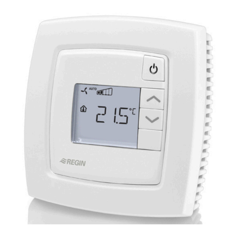
Regin OPTIGO ARDO User manual

en
WE TAKE BUILDING
AUTOMATION PERSONALLY
MANUAL
OPTIGOARDO

Rev. A, 2022-02-09
THANK YOU FOR CHOOSING REGIN!
Ever since Regin was established in 1947, we have developed and marketed prod cts and systems that create good
levels of indoor comfort. Today, we are an important player with one of the market's broadest ranges for b ilding
a tomation.
O r goal is to make real estates in the world more energy efficient. Regin is an international gro p and o r prod cts
sells in over 90 co ntries. Thanks to o r global presence with strong local representation, we are well aware of the
req irements of the market, as well as of how o r prod cts and systems f nction nder the most variable conditions.
Every year, Regin makes s bstantial investments in the development of o r systems and HVAC-prod cts.
DISCLAIMER
The information in this man al has been caref lly checked and is believed to be correct. Regin makes no warranties
abo t the contents of this man al and sers are req ested to report errors and discrepancies to Regin, so that
corrections may be made in f t re editions. The information in this doc ment is s bject to change witho t prior
notification.
Some prod ct names mentioned in this doc ment are sed for identification p rposes only and may be the registered
trademarks of their respective companies.
© AB Regin. All rights reserved.

Table of Contents
Introduction .................................................................................................................................5
1.1 Abo t this man al...............................................................................................................5
1.2 More information................................................................................................................5
1.3 Display ..............................................................................................................................5
1.4 Upgrade and back p of OptigoArdo........................................................................................6
2 Information for the end user ........................................................................................................7
2.1 LED:s and b ttons ..............................................................................................................7
2.1.1 Display .................................................................................................................7
2.1.2 LED:s...................................................................................................................7
2.1.3 S mmary of the f nction of the b ttons...................................................................8
2.2 Navigating the men s..........................................................................................................8
2.3 Changing val es..................................................................................................................9
2.3.1 Editing an existing val e.........................................................................................9
2.3.2 Enter a completely new val e ...............................................................................10
2.3.3 Confirm the change .............................................................................................10
2.3.4 Undo an initiated change ......................................................................................10
2.4 Logging on and off.............................................................................................................10
2.4.1 Log on ................................................................................................................10
2.4.2 Log off................................................................................................................11
2.4.3 Change password.................................................................................................11
2.4.4 A tomatic logoff .................................................................................................12
2.5 Men str ct re.................................................................................................................12
2.5.1 Ventilation..........................................................................................................13
2.5.2 Time settings.......................................................................................................14
2.5.3 Inp ts/O tp ts ...................................................................................................17
2.5.4 Mode switch .......................................................................................................17
2.6 Alarm handling.................................................................................................................17
2.6.1 Alarm priorities ...................................................................................................17
2.6.2 Inspect alarms .....................................................................................................18
2.6.3 Acknowledge, block and nblock alarms ................................................................18
3 Information for the specialist...................................................................................................... 9
3.1 F nction overview.............................................................................................................19
3.2 Temperat re control .........................................................................................................21
3.2.1 General...............................................................................................................21
3.2.2 Control modes.....................................................................................................21
3.3 Temperat re seq ences .....................................................................................................22
3.3.1 Heater ...............................................................................................................23
3.3.2 Exchanger...........................................................................................................26
3.3.3 Cooler ................................................................................................................27
3.3.4 Mixing damper....................................................................................................27
3.4 Fan control .......................................................................................................................28
3.4.1 Fan levels ............................................................................................................28
3.5 CO2control......................................................................................................................28
3.6 Free cooling......................................................................................................................28
3.7 S pport control ................................................................................................................29
3.8 Fire..................................................................................................................................29
3.9 Filter monitoring...............................................................................................................29
3.10 Dampers ..........................................................................................................................29
3.11 Changing the battery.........................................................................................................29
4 Information for the specialist - Configuration .............................................................................3
4.1 Predefined config rations in OptigoArdo...............................................................................31
4.1.1 How to se the predefined config rations ..............................................................33
4.2 Adj st settings in OptigoArdo ..............................................................................................33
4.3 Config ration of OptigoArdo ...............................................................................................34
Table of Contents
4.3.1 System................................................................................................................34
4.3.2 F nction config ration .........................................................................................36
4.3.3 Inp ts/O tp ts ...................................................................................................41
4.3.4 Other config ration .............................................................................................43
4.4 Ventilation .......................................................................................................................44
4.4.1 Act al / Setpoint .................................................................................................44
4.4.2 Temperat re control............................................................................................47
4.4.3 Fan control..........................................................................................................49
4.4.4 Demand control ..................................................................................................50
4.4.5 PID controllers ....................................................................................................51
4.4.6 Man al / A to.....................................................................................................53
4.4.7 Stat s .................................................................................................................56
4.5 Alarm events ....................................................................................................................57
4.6 Time settings ....................................................................................................................57
4.6.1 Extra time channel...............................................................................................59
4.6.2 Holiday calendar..................................................................................................59
4.7 Inp ts/O tp ts.................................................................................................................59
4.8 Alarms stat s....................................................................................................................59
4.8.1 Alarm config ration.............................................................................................60
4.8.2 S m alarm ..........................................................................................................60
4.8.3 Alarm limits ........................................................................................................60
4.9 Access rights.....................................................................................................................60
4.9.1 Log on ................................................................................................................61
4.9.2 Change password.................................................................................................61
5 Information for the installer........................................................................................................63
5.1 Installation .......................................................................................................................63
5.1.1 OptigoArdo ..........................................................................................................63
5.2 Commissioning.................................................................................................................67
5.3 Resetting the controller......................................................................................................67
Appendix A technical data ...........................................................................................................68
A.1 OptigoArdo ........................................................................................................................68
A.1.1 General data........................................................................................................68
A.1.2 Ethernet port data................................................................................................68
A.1.3 Inp ts & o tp ts..................................................................................................68
Appendix B Model overview .......................................................................................................69
Appendix C Input and output lists ...............................................................................................70
C.1 Analog inp ts ...................................................................................................................70
C.2 Digital inp ts....................................................................................................................70
C.3 Universal inp ts................................................................................................................70
C.4 Analog o tp ts .................................................................................................................71
C.5 Digital o tp ts..................................................................................................................71
Appendix D Alarm list .................................................................................................................72
D.1 .......................................................................................................................................72
Appendix E Terminal lists.............................................................................................................74
E.1 OptigoArdo ........................................................................................................................74

Introduction
Introduction
. About this manual
This man al covers all the models in the OptigoArdo series.
The man al has the following main chapters:
✓Information for the end ser
All the information needed by the end ser. How to handle the controller, incl ding how to navigate
in the men s, LED:s and indications, how to change setpoints and handle alarms etc.
✓Information for the specialist
A comprehensive g ide to all the f nctions of the controller.
✓Information for the installer
Everything related to the installation of the hardware, s ch as wiring examples and commissioning.
✓Appendix
Technical data, model overview, inp t and o tp t lists, alarm list, terminal lists.
Special text formats sed in the man al:
NNoottee!! This box and symbol is used to show useful tips and tricks.
CCaauuttiioonn!! This type of text and symbol is used to show cautions.
WWaarrnniinngg!! This type of text and symbol is used to show warnings.
This box is used to show formulas and mathematical calculations
This box is used to
represent the display
window on the
controller
.2 More information
More information abo t the controller is available in:
✓Prod ct sheet for OptigoArdo
✓Instr ction for OptigoArdo
✓List of predefined config rations for OptigoArdo
All the above doc ments are available for download from Regin’s website, www.regincontrols.com
.3 Display
There is a text display in the OptigoArdo
The display is sed to e.g. change val es, set timers and monitor alarms.
OptigoArdo manual, Rev. A 5 (76)

Introduction
.4 Upgrade and backup of OptigoArdo
There is an online tool available for OptigoArdo. The tool is sed to pgrade the controller and for back p and
to restore the settings.
A LAN/Ethernet comm nication cable is req ired in order to connect to the controller, and the controller
m st also be powered p.
6 (76) OptigoArdo manual, Rev. A

Information for the end user
2 Information for the end user
The OptigoArdo is a 24 V pre config red ventilation controller with display for se in ventilation applications.
2. LED:s and buttons
The controller has an internal text display and feat res 7 b ttons.
2. . Display
The display has 4 rows of 20 characters each. It has backgro nd ill mination. The ill mination is normally
off, b t is activated as soon as a b tton is pressed. The ill mination will be t rned off again after a period of
inactivity.
2. .2 LED:s
The controller has two LEDs in the front marked with the symbols (alarm) and (change).
Symbol Colour Function
Flashing red There are one or more unacknowledged
alarms.
Fixed red There are one or more remaining acknowl-
edged alarms.
Flashing yellow You are in a dialog box where it is possible
to switch to change mode.
A quick blinking (2 times/s) indicates that
the parameter can be changed using the
current access level.
A slower blinking (1 time/s) indicates that a
higher access level is required to change
the parameter.
Fixed yellow You are in change mode.
Status indication
Stat s indication LEDs can be fo nd in the pper left corner of the OptigoArdo.
Designation Colour Description
TCP/IP Yellow/Green Green: Connected to other network
equipment
Blinking green: Network traffic
Blinking yellow: For identifying
P/B (Power / Battery) Green/Red Power on / Battery error
OptigoArdo manual, Rev. A 7 (76)

Information for the end user
2. .3 Summary of the function of the buttons
OptigoArdo (7 buttons) Functions Function in Alarm Mode
[▲][▼][►][◄] Navigation buttons:
▲ Navigate upwards.
▼ Navigate downwards.
► Navigate to the right.
◄ Navigate to the left.
In change mode:
◄ Move cursor to the left.
► Move cursor to the right.
▲ Increase the value by 1.
▼ Decrease the value by 1.
▲and ▼ Scroll among the texts when
there are several alternatives.
▲ Navigate up in the alarm stack.
▼ Navigate down in the alarm stack.
◄ Exit alarm display mode.
[OK] ✓Enter change mode.
✓Confirm a new value in change mode.
An input must be confirmed with this
button in order to change the value in
the controller.
When a value has been confirmed, the
cursor will move to the next editable
value in the current box.
✓A menu with all actions that are avail-
able for the current alarm is displayed.
[C] ✓Enter change mode and erase the value
in the display.
✓Erase the sign at the cursor.
✓When the current value is completely
empty, the edit mode is cancelled and
the cursor will move to the next value
that will also be erased in the window.
✓Undo (erase) the input
✓Closes the menu containing available
alarm actions without changing the state
of the alarm point.
[ALARM] ✓Enter alarm display mode. ✓Browse among alarms in alarm display
mode.
2.2 Navigating the menus
The appearance of the start display may vary since there are several different start displays to choose from
d ring config ration.
Optigo Ardo 1.0
2021-06-09 14:29
System: Normal run
Sp: 22.0 Act: 22.5°C
Sp and Act stand for Setpoint and Act al val e.
Act al val e = the c rrent meas red temperat re
Setpoint = the desired config red temperat re
Yo can navigate thro gh the men choices at this level by pressing the [▼]and [▲]b ttons.
8 (76) OptigoArdo manual, Rev. A

Information for the end user
Which men items that are shown depends on the access level of the ser and the config red inp ts/o tp ts
and f nctions.
Below, all possible men entries are shown.
✓Ventilation
✓Alarm events
✓Time settings
✓Inp ts/O tp ts
✓Config ration
✓Alarm stat s
✓Access rights
To enter a higher men level, press the [►]b tton when the display marker is located at the men item yo
wish to enter. At each level there may be several new men s thro gh which yo may browse sing the [▲]
and [▼]b ttons.
When there are f rther s bmen s linked to a men or men item, it is indicated by an arrow symbol at the
right-hand edge of the display. To choose one, press the [►]b tton again. To ret rn to a lower men level,
press the [◄]b tton.
2.3 Changing values
When yo are at a position where it is possible to change one or more val es, and yo r access level is high
eno gh, yo can edit the existing val e, or enter a new one. After changing the val e, yo confirm the inp t
with the [OK] b tton, or ndo the change by pressing the [C]/[▼►]b ttons for a short while ntil the
original val e reappears in the window and change mode is exited. These actions are described in detail in
the following sections.
2.3. Editing an existing value
1. Press the [OK] b tton to go to change mode. A flashing c rsor appears. If there are m ltiple editable
val es in one men , press the [OK] b tton ntil the val e yo want to change flashes.
2. Move the c rsor to the right and to the left with the navigation b ttons [►]and [◄].
3. The val e at the c rsor can now be changed in the following ways:
✓Erase the c rrent digit or character with the [C]/[▼►]b ttons.
✓Use the [▲]and [▼]b ttons to increase or decrease the val e at the c rsor. Editable texts can also
be changed with this method.
✓If the character at the c rsor is a decimal point, yo cannot browse with the [▲]and [▼]b ttons.
Yo can however erase the decimal point with the [C]/[▼►]b ttons.
✓If the c rsor is placed to the right of the val e, i.e. the character at the c rsor is a space, yo can
add a decimal point with the [▼]b tton, or the fig re 0 with the [▲]b tton.
✓If yo req ire a negative n mber, move the c rsor to the leftmost position and press the [▼]
b tton to get a min s sign. Then edit the following digits to the req ired val e.
✓Scroll p [▲]and down [▼]to browse thro gh texts when there are several texts to choose from
instead of n merical val es.
OptigoArdo manual, Rev. A 9 (76)

Information for the end user
2.3.2 Enter a completely new value
✓Press the [C] /[▼►]b ttons to go to change mode. The val e is erased in the window, and yo have to
enter a completely new val e.
✓If yo req ire a negative n mber, move the c rsor to the leftmost position and press the [▼]b tton to
get a min s sign. Then edit the following digits to the req ired val e.
✓Press [▲]to begin the inp t with the digit 0, then browse to the req ired digit or character with [▲]
and [▼].
✓Press [▼]to get a decimal point. When the c rsor is placed at a decimal point, yo cannot browse with
the [▲]and [▼]b ttons.
2.3.3 Confirm the change
Press [OK] to confirm the change when the req ired val e has been entered. Then the val e yo see in the
window will be pdated in the installation.
After the val e has been confirmed, the c rsor will move to the next editable val e in the c rrent men .
NNoottee!! As long as you don’t confirm a change with the [[OOKK]] button, no change will be made in the
installation.
2.3.4 Undo an initiated change
NNoottee!! As long as you don’t confirm a value with the [[OOKK]] button, you can undo an initiated change by
pressing the [[CC]] /[[▼▼►►]] buttons for a short while until the original value reappears in the window and
change mode is exited.
2.4 Logging on and off
The controller has fo r different access levels. The choice of access level determines which men s are shown,
as well as which parameters can be changed in the displayed men s.
✓Guest level does not req ire logging on, and only permits changes in r nning mode and gives read-only
access to a limited n mber of men s.
✓Operator level gives the same access as Guestl level, and in addition, access to change setpoints.
✓Service level gives the same access as Operator level, and in addition, access to change controller
settings and man al mode.
✓Admin level gives f ll read/write access to all settings and parameters in all men s.
2.4. Log on
1. Browse to Access Rights in the main men and press [►].
Log on
Log off
Change password
0 (76) OptigoArdo manual, Rev. A

Information for the end user
2. Select Log on and press [►].
Log on
Enter password:****
Actual level:
None
3. Press [OK] to make a c rsor marker appear at the first digit position.
4. Enter the password (4-digit code) by pressing [▲]ntil the correct digit is displayed. Press the [►]to
move to the next position. Repeat the proced re ntil all fo r digits are displayed, and press [OK] to
confirm.
2.4.2 Log off
1. Go to Access Rights in the main men and press [►].
2. Select Log off and press [►].
Log off?
No
Actual level:
Admin
3. Select Yes and press [OK].
2.4.3 Change password
1. Go to Access Rights in the main men and press [►].
2. Select Change password and press [►].
Change password for
level:Operator
New password: ****
3. Select Yes and press [OK]
4. Press [OK] to enter change mode.
5. Use the [▲]and [▼]b ttons to browse and select the access level to change the password for, and press
[OK] to confirm.
OptigoArdo manual, Rev. A (76)

Information for the end user
6. Enter the new password (4-digit code) by pressing [▲]ntil the correct digit is displayed. Press the [►]
to move to the next position. Repeat the proced re ntil all fo r digits are displayed, and press [OK] to
confirm.
The following passwords are the defa lt for the different access levels:
Access level Password
Admin 1111
Service 2222
Operator 3333
Guest 5555
Yo can only change the password for access levels lower or eq al to the presently active level, i.e. if
yo are logged in as Admin yo can change all passwords, b t as Operator yo can only change the
Operator and Guest passwords. There is no point in changing the Guest password since access to that
level is granted a tomatically to all sers.
CCaauuttiioonn!! Do not set the password for two different access levels to the same value, as this
would prevent access to the higher of these two access levels. This is especially important for
the AAddmmiinn level.
NNoottee!! If the password for the AAddmmiinn level has been changed and then lost, a temporary pass-
word can be obtained from Regin. This code is date dependent and valid for one day only.
2.4.4 Automatic logoff
When logged in as Operator,Service or Admin, the ser will a tomatically be logged off to Guest after a
settable time of inactivity (the defa lt is 60 seconds). It is possible to disable the a tomatic logoff.
Change password to remove automatic logoff
If yo want to remove the a tomatic logoff, change the password of the desired level to 0000. This can be
very sef l in certain cases if the nit is intended to be sed by trained personnel or, for instance, d ring
commissioning.
NNoottee!! Removing the automatic logoff should be done with consideration, since no alarm is continu-
ously given that a certain level has been activated.
2.5 Menu structure
The display is sed to select predefined config rations for the system, and to change some settings.
Start men :
Ventilation
Alarm events
Time settings
Inputs/Outputs
Configuration
Alarm status
Access rights
2 (76) OptigoArdo manual, Rev. A

Information for the end user
2.5. Ventilation
Ventilation has p to seven s bmen s:
Actual/Setpoint
Temperature control
Fan control
Demand control
PID controllers
Manual/Auto
Status
Actual/Setpoint
In this s bmen , yo can read all the act al val es of the config red inp ts of the circ it. For more
information, see 4.4.1 Actual / Setpoint.
Temperature control
In this s bmen , yo can read and set all the setpoints for the selected circ it. Yo need Operator or higher
access level to be able to change setpoints. For more information see 4.4.2 Temperature control.
Fan control
In this s bmen , settings of the fan can be read and set. It is only visible for access level Operator and higher,
and only editable for access level Service and higher. For more information, see 4.4.3 Fan control.
Demand control
In this s bmen , settings for Demand control can be read and set. It is only visible for access level Operator
and higher, and only editable for access level Service and higher. For more information, see 4.4.4 Demand
control.
PID control
In this s bmen , the control parameters can be read and set. It is only visible for access level Operator and
higher, and only editable for access level Service and higher. For more information, see 4.4.5 PID controllers.
Manual/Auto
In this s bmen , the ventilation nit can be set to man al mode. It is only visible for access level Operator
and higher, and only editable for access level Service and higher.
For more information, see 4.4.6 Manual / Auto.
Status
In this s bmen , the stat s of the ventilation nit can be read.
Each f nction also has different s b-stat ses. For more information, see 4.4.7 Status.
OptigoArdo manual, Rev. A 3 (76)

Information for the end user
2.5.2 Time settings
OptigoArdo has a year-based clock f nction. This means that a week-sched le with holiday periods for a f ll
year can be set. The clock has an a tomatic s mmertime/wintertime change-over.
It has individ al sched les for each weekday pl s a separate holiday setting. Up to 24 individ al holiday
periods can be config red. A holiday period can be anything from one day p to 365 days. Holiday sched les
take precedence over other sched les.
Each day has p to fo r individ al r nning periods. There are daily individ al sched les for low speed,
normal speed and high speed of the fan, each with p to fo r r nning periods.
One o tp t can be sed as a timer controlled o tp t, with individ al week-sched les with fo r activation
periods per day. This o tp t can be sed to control lighting, door locks etc.
The Time settings men contains the s bmen s Time schedule,oliday schedule and Time/Date.
Time schedule
Holiday schedule
Time/Date
Time settings
Fan low speed
Fan normal speed
Fan high speed
Extra time channel
In the time sched les, fo r periods are available for each day of the week. Also, fo r periods are available for
days that are config red as holidays in the holiday sched le. D ring the periods the assigned circ it is
working with the corresponding setpoint. O tside of a period the system is off.
Occupation time
Begin/End
OffOff
OnOn
Off
E1B1E2B2
Figure 2-1 Time schedule
The above fig re shows an example of period states. It is not possible for periods to overlap each other.
Timer Low speed, Normal speed, High speed
There are sixteen separate settings men s for each timer channel, two for each weekday and two extra for
holidays. Holiday sched les take precedence over other sched les.
4 (76) OptigoArdo manual, Rev. A

Information for the end user
For 24 ho r r nning, set a period to 00:00 - 24:00.
To inactivate a period, set the time to 00:00 - 00:00. If all periods of a day are set to 00:00 - 00:00, the nit
will not r n that day.
Normal speed
Monday Per3-4 >
Per 1: 00:00 - 24:00
Per 2: 00:00 - 00:00
Normal speed
Monday
Per 3: 00:00 - 00:00
Per 4: 00:00 - 00:00
If yo want to r n the nit from one day to another, e.g. from Monday 22:00 to T esday 09:00, the desired
r nning time for both m st be entered.
Normal speed
Monday
Per 1: 22:00 - 24:00
Per 2: 00:00 - 00:00
Normal speed
Tuesday
Per 1: 00:00 - 09:00
Per 2: 00:00 - 00:00
Sho ld periods for the different speeds overlap, high speed takes precedence over normal speed, and normal
speed takes precedence over low speed.
Extra time channel
One digital o tp t can be sed as a timer controlled o tp t with individ al week-sched les and fo r
activation periods per day. The o tp t has sixteen separate setting men s; two for each weekday and two
extra for holidays. Holiday sched les take precedence over other sched les.
Extra time channel1
Wednesday Per3-4 >
Per 1: 00:00 - 00:00
Per 2: 00:00 - 00:00
Extra time channel1
Wednesday
Per 3: 00:00 - 00:00
Per 4: 00:00 - 00:00
Parameters (Fan normal speed)
Name Unit Min Max Default Description
Monday Per.1 Start hh:mm 00:00 24:00 00:00 Start of period 1 Mondays.
Monday Per.1 End hh:mm 00:00 24:00 24:00 End of period1 Mondays.
Monday Per.2 Start hh:mm 00:00 24:00 00:00 Start of period 2 Mondays.
Monday Per.2 End hh:mm 00:00 24:00 00:00 End of period 2 Mondays.
Monday Per.3 Start hh:mm 00:00 24:00 00:00 Start of period 3 Mondays.
Monday Per.3 End hh:mm 00:00 24:00 00:00 End of period 3 Mondays.
Monday Per.4 Start hh:mm 00:00 24:00 00:00 Start of period 4 Mondays.
Monday Per.4 End hh:mm 00:00 24:00 00:00 End of period 4 Mondays.
...
OptigoArdo manual, Rev. A 5 (76)

Information for the end user
Name Unit Min Max Default Description
Holiday Per.1 Start hh:mm 00:00 24:00 00:00 Start of period 1 holidays.
Holiday Per.1 End hh:mm 00:00 24:00 00:00 End of period 1 holidays.
Holiday Per.2 Start hh:mm 00:00 24:00 00:00 Start of period 2 holidays.
Holiday Per.2 End hh:mm 00:00 24:00 00:00 End of period 2 holidays.
Holiday Per.3 Start hh:mm 00:00 24:00 00:00 Start of period 3 holidays.
Holiday Per.3 End hh:mm 00:00 24:00 00:00 End of period 3 holidays.
Holiday Per.4 Start hh:mm 00:00 24:00 00:00 Start of period 4 holidays.
Holiday Per.4 End hh:mm 00:00 24:00 00:00 End of period 4 holidays.
Parameters (Fan low and high speed, Extra time channel)
Name Unit Min Max Default Description
Monday Per.1 Start hh:mm 00:00 24:00 00:00 Start of period 1 Mondays.
Monday Per.1 End hh:mm 00:00 24:00 00:00 End of period 1 Mondays.
Monday Per.2 Start hh:mm 00:00 24:00 00:00 Start of period 2 Mondays.
Monday Per.2 End hh:mm 00:00 24:00 00:00 End of period 2 Mondays.
Monday Per.3 Start hh:mm 00:00 24:00 00:00 Start of period 3 Mondays.
Monday Per.3 End hh:mm 00:00 24:00 00:00 End of period 3 Mondays.
Monday Per.4 Start hh:mm 00:00 24:00 00:00 Start of period 4 Mondays.
Monday Per.4 End hh:mm 00:00 24:00 00:00 End of period 4 Mondays.
...
Holiday Per.1 Start hh:mm 00:00 24:00 00:00 Start of period 1 holidays.
Holiday Per.1 End hh:mm 00:00 24:00 00:00 End of period 1 holidays.
Holiday Per.2 Start hh:mm 00:00 24:00 00:00 Start of period 2 holidays.
Holiday Per.2 End hh:mm 00:00 24:00 00:00 End of period 2 holidays.
Holiday Per.3 Start hh:mm 00:00 24:00 00:00 Start of period 3 holidays.
Holiday Per.3 End hh:mm 00:00 24:00 00:00 End of period 3 holidays.
Holiday Per.4 Start hh:mm 00:00 24:00 00:00 Start of period 4 holidays.
Holiday Per.4 End hh:mm 00:00 24:00 00:00 End of period 4 holidays.
Holiday schedule
The system operator can define specific periods of operation or non-operation thro gho t the year. D ring
these defined periods, the settings in the week sched le do not apply. The holiday sched le provides 24
periods. All holiday periods are working with a special day plan with a maxim m of 4 periods.
A holiday period can be any n mber of consec tive days from 1…365. The dates are in the format: MM:DD.
When the present date falls within a holiday period, the sched ler will se the settings for the weekday
oliday.
Parameters
Name Unit Min Max Default Description
Holiday Per.1 Start MM:DD 01:01 12:31 01:01 The start date of holiday period 1.
Holiday Per.1 End MM:DD 01:01 12:31 01:01 The end date of holiday period 1.
...
6 (76) OptigoArdo manual, Rev. A

Information for the end user
Name Unit Min Max Default Description
Holiday Per.24 Start MM:DD 01:01 12:31 01:01 The start date of holiday period 24.
Holiday Per.24 End MM:DD 01:01 12:31 01:01 The end date of holiday period 24.
Time/Date
This men displays time, date and weekday, and it permits the setting of time and date.
Time is shown in 24 ho r format.
Date is shown in the format YY:MM:DD.
2.5.3 Inputs/Outputs
In the s b men Inp ts/O tp ts yo can find raw val es and analog and digital inp ts and o tp ts. For more
information see 4.7 Inputs/ utputs.
Raw values
Analog inputs
Digital inputs
Analog outputs
Digital outputs
2.5.4 Mode switch
In addition to the items in the main men , there is also an extra men called Mode switch, that is reached by
pressing [►]in the main men . The mode switch changes the operation of the system.
Mode switch position
0 — Off Manual mode Off. System is switched off. No control function.
1 — Auto Automatic mode. Control function depending on timer and settings.
2 — Low speed Manual mode. System is forced to low speed of the fans.
3 — Normal speed Manual mode. System is forced to normal speed of the fans.
4 — High speed Manual mode. System is forced to high speed of the fans.
2.6 Alarm handling
Alarms are indicated by the red alarm LED on the front of the nit. If an alarm condition occ rs, an alarm is
logged in an alarm list. The list shows the type of alarm, the alarm date and time and the alarm priority (A, B
or C alarm).
2.6. Alarm priorities
Alarms can be given different priority levels: A alarm,B alarm,C alarm or not active. There is one digital
o tp t that can be sed as alarm o tp t: Sum alarm.
✓A and B alarms activate the s m alarm o tp t, if it has been config red.
✓Class C alarms are removed from the alarm list when the alarm inp t resets even if the alarm has not
been acknowledged.
OptigoArdo manual, Rev. A 7 (76)

Information for the end user
2.6.2 Inspect alarms
✓Press the alarm b ttons [ALARM] /[◄▲]to display the alarms.
✓If there is more than one alarm at the same time, this is indicated by p/down arrow symbols at the
right-hand edge of the display. Yo can browse among them in two ways:
1. By sing the navigation b ttons [▼]and [▲].
2. By pressing the alarm b ttons [ALARM] /[◄▲]several times.
✓Press [◄]to exit alarm handling and ret rn to the previo s men .
2.6.3 Acknowledge, block and unblock alarms
✓Press the [OK] b tton to get a men with the available alarm actions for the c rrently displayed alarm.
✓Select the req ired alarm action with the b ttons [▼]and [▲].
✓Press the [OK] b tton to exec te the action.
At the left end of the bottom display line the alarm stat s is shown. For active, nacknowledged alarms the
space is blank. Alarms that have been reset are indicated by the text Acknowledged. Active or blocked
alarms are indicated by the text Acknowledged or Blocked.
Acknowledged alarms will remain on the alarm list ntil the alarm inp t signal resets.
Blocked alarms remain on the alarm list ntil the alarm has been reset and the block has been removed. New
alarms of the same type will not be activated as long as the block remains.
CCaauuttiioonn!! Blocking alarms can be potentially dangerous. A high log on access level is therefore required
to block alarms.
Alarm events
In the Alarm Events men , there is an alarm log which contains the 100 latest alarm events. The latest event
is shown at the top of the list. The alarm log is only sed to view alarm history, which may simplify
tro bleshooting of the installation.
8 (76) OptigoArdo manual, Rev. A

Information for the specialist
3 Information for the specialist
3. Function overview
The selected control modes and activated f nctions depends on the selected config ration. Find more
information abo t the available config rations in the doc ment Optigo Ardo 1.0 - Predefined
config rations, which is available on Regin's homepage www.regincontrols.com. A description abo t the
activation of a config ration will be fo nd in chapter 4.1 Predefined configurations in ptigoArdo.
The program for an air handling nit contains, apart from other things, the following f nctions:
Different temperature control modes
✓S pply air temperat re control
✓Room temperat re control (cascade control)
✓Extract air control (cascade control)
With control of:
✓Heat exchangers (plate)
✓Mixing dampers
✓Heating coil (water with or witho t frost protection, electric with high temperat re limit switch)
✓Cooling (water)
✓Circ lation p mps
Fan control
✓1- or 2-speed s pply air and extract air fans
✓Man al control of fans
Timer control
For starting and stopping the nit, ann al clock f nction. One o tp t for control of external f nctions s ch
as lighting, door locks etc.
Demand controlled ventilation
In b ildings with strongly varying occ pancy, the fan speeds or mixing dampers can be controlled by the air
q ality meas red by a CO2sensor.
Support control
When sing the control f nction room control or extract air temperat re control, it is possible to tilise
s pport-heating and/or s pport-cooling.
Free cooling
When this f nction has been activated, it is sed d ring the s mmer to cool the b ilding d ring the night
sing cool o tdoor air, thereby red cing the need to r n chillers d ring the day.
Free heating
If the o tdoor temperat re is higher than the indoor temperat re and there is a heating demand, the
recovery damper will not open for recovery b t instead open f lly for o tdoor air. This may occ r d ring low
night-time o tdoor temperat res, when the room has been cooled considerably and the o tside heat is rising
faster than indoors. This f nction is activated at the same time as Free cooling.
Cooling recovery
If the cooling recovery has been config red, there is a cooling req irement and the extract air or room
temperat re is a settable amo nt lower than the o tdoor temperat re, th s cooling recovery can be
OptigoArdo manual, Rev. A 9 (76)

Information for the specialist
activated. When cooling recovery is activated the heat exchanger and damper seq ence o tp t signal will be
activated in the cooling demand. The f nction also activates the heating f nction Free heating: if heating is
req ired and the o tdoor temperat re is higher than the extract air or room temperat re, o tdoor air will
primarily be sed.
Change-over
In 2-pipe systems where a combination heater/cooler is operating together with a heat p mp, change-over is
a f nction that enables sing the same pipe for both heating and cooling, depending on which is c rrently
req ired.
20 (76) OptigoArdo manual, Rev. A
This manual suits for next models
2
Table of contents
Other Regin Controllers manuals

Regin
Regin RVAZ4L1-230 User manual

Regin
Regin EXOcompact C80 User manual

Regin
Regin PULSER-M User manual

Regin
Regin RVAZ4L1-24 User manual

Regin
Regin CORRIGO L10 User manual

Regin
Regin AL24A2D User manual

Regin
Regin RVAN10-230 User manual

Regin
Regin RVAZ4-24A User manual

Regin
Regin Corrigo User manual

Regin
Regin Regio Eddo User manual

Regin
Regin SPINN/D User manual

Regin
Regin REGIOEEDO User manual

Regin
Regin RVAN10-24 User manual

Regin
Regin RVAN5-24A User manual

Regin
Regin RVAN25-24 User manual

Regin
Regin RVAB4-24 User manual

Regin
Regin RVAZ4-24A User manual

Regin
Regin RVAN10-24A User manual

Regin
Regin Corrigo U10 Series User manual

Regin
Regin RVAN5-24 User manual