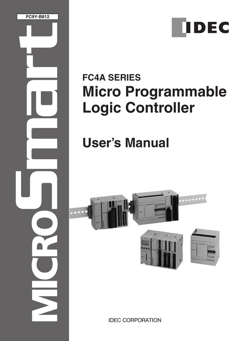
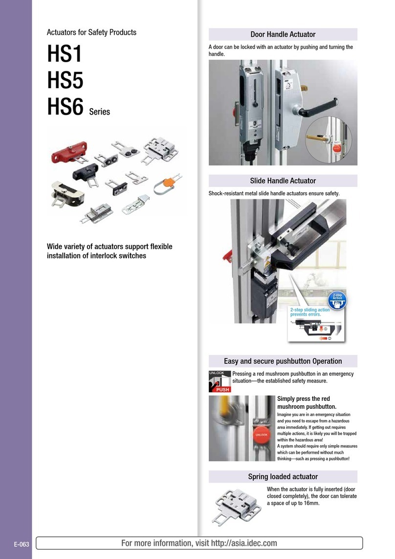
IDEC HS9Z-FL54 User manual

Double
Action
Padlock
Hole
UnLock
Robust & Shock Resistant
Ensures safety of workers
Interlock Switches with Solenoid
Slide Handle Actuator for HS1T

1 2 3
Even if an operator is trapped inside the hazardous area, the operator can escape by unlocking the lock using the rear
unlocking button and by sliding the lever to open the door. (Only when using the HS1T rear unlocking button model. Use
with an optional manual rear unlocking button kit for frame).
Push the rear unlocking button
to release the lock and stop the
hazard.
Slide the lever. Open the door and escape.
ANSI/RIA R15.06-1999 11.2.2 Interlocking portion
b) The interlocking portion of the interlocked barrier shall be installed, applied, and maintained so that:
8) be capable of being easily unlocked from the inside of the safeguarded space with or without power available, when the possibility of full body access exists;
Rear lever
Press the red button in
case of an emergency
PUSH for Safety
Rear unlocking button kit
(HS9Z-FL5: optional)
Rear unlocking button kit
(HS9Z-FL5: optional)
Rear unlocking button
UnLock
Interlock SwitchInterlock Switch
Slide handle actuators are user-friendly accessories for HS1T interlock switches.
The slide handle actuator supports 4-way operation (left/right door, sliding door/opening door) and prevents workers
from being conned in hazardous areas, creating a safe work environment.
Shock-resistant metal slide handle actuators
ensure a safe work environment
When inserting the actuator, unlatch the knob, slide the handle.
Two-step action prevents handles from inadvertend operation.
1
12
2
Grab the handle, and pull the knob to unlatch. Slide the handle and insert the actuator.
Double
Action
Double
Action
Two-step action prevents inadvertent operation
Padlocks can be installed on the padlock hole. By using padlocks, other operators
cannot operate the slide handle actuator, preventing inadvertent operation of machines and
ensuring safety of operators.
8.4 Protection of personnel within the safeguarded space
Personnel required to perform tasks within the safeguarded space shall be protected by:
a) Preventing the re-initiation of any motion or hazardous process while personnel are within the safeguarded space, for example locking
a gate open;
(padlocks must be purchased by the customer)
Padlock
Hole
Padlock
Hole
Padlock
Emergency escape from inside hazardous areas
Shock-resistant and robust structure ideal
for heavy doors.
Sliding features eliminate the need for angle
adjustment, enabling easy installation.
Metal actuators suitable
for heavy doors
UnLock
Padlock holePadlock hole
Knob
2

1 2 3
Even if an operator is trapped inside the hazardous area, the operator can escape by unlocking the lock using the rear
unlocking button and by sliding the lever to open the door. (Only when using the HS1T rear unlocking button model. Use
with an optional manual rear unlocking button kit for frame).
Push the rear unlocking button
to release the lock and stop the
hazard.
Slide the lever. Open the door and escape.
ANSI/RIA R15.06-1999 11.2.2 Interlocking portion
b) The interlocking portion of the interlocked barrier shall be installed, applied, and maintained so that:
8) be capable of being easily unlocked from the inside of the safeguarded space with or without power available, when the possibility of full body access exists;
Rear lever
Press the red button in
case of an emergency
PUSH for Safety
Rear unlocking button kit
(HS9Z-FL5: optional)
Rear unlocking button kit
(HS9Z-FL5: optional)
Rear unlocking button
UnLock
Interlock SwitchInterlock Switch
Slide handle actuators are user-friendly accessories for HS1T interlock switches.
The slide handle actuator supports 4-way operation (left/right door, sliding door/opening door) and prevents workers
from being conned in hazardous areas, creating a safe work environment.
Shock-resistant metal slide handle actuators
ensure a safe work environment
When inserting the actuator, unlatch the knob, slide the handle.
Two-step action prevents handles from inadvertend operation.
1
12
2
Grab the handle, and pull the knob to unlatch. Slide the handle and insert the actuator.
Double
Action
Double
Action
Two-step action prevents inadvertent operation
Padlocks can be installed on the padlock hole. By using padlocks, other operators
cannot operate the slide handle actuator, preventing inadvertent operation of machines and
ensuring safety of operators.
8.4 Protection of personnel within the safeguarded space
Personnel required to perform tasks within the safeguarded space shall be protected by:
a) Preventing the re-initiation of any motion or hazardous process while personnel are within the safeguarded space, for example locking
a gate open;
(padlocks must be purchased by the customer)
Padlock
Hole
Padlock
Hole
Padlock
Emergency escape from inside hazardous areas
Shock-resistant and robust structure ideal
for heavy doors.
Sliding features eliminate the need for angle
adjustment, enabling easy installation.
Metal actuators suitable
for heavy doors
UnLock
Padlock holePadlock hole
Knob
3

Shock-resistant slide handle actuators ensure a safe work environment
Specifications
Applicable interlock switches (*1) HS1T interlock switches with solenoid
Operating temperature -30 to +70C (no freezing)
Mechanical durability 100,000 operations minimum
Applicable padlock shackle diameter ø6 to 13
Padlock withstand load 50N minimum
Handle travel (approx.) 80mm (removed <—>inserted)
Weight (approx.) 2,000g
*1) Be sure to use a HS1T interlock switches with rear unlocking button.
• The interlock switch must be prepared by the customer.
• For specications on the interlock switch, see HS1T catalog.
HS1T slide handle actuator Package quantity: 1
Item Part No.
Ordering No. Remarks
Slide handle actuator HS9Z-EH1L Used with an interlock switch
Manual rear unlocking button kit for frame
(*1)
HS9Z-FL54 Thickness of mounting part (*2) (Y): 30≤Y≤35 (mm)
HS9Z-FL55 Thickness of mounting part (*2) (Y): 35<Y≤45 (mm)
[HS9Z-FL56] Thickness of mounting part (*2) (Y): 45<Y≤55 (mm)
[HS9Z-FL57] Thickness of mounting part (*2) (Y): 55<Y≤65 (mm)
*1) Must be purchased when using a HS1T rear unlocking button model (sold separately)
*2) Mounting part refers to a part where the product will be attached (such as a frame).
• Items in [ ] are not for standard sale. To order, contact IDEC.
• For other panel thickness, contact IDEC.
Parts description
Rear lever (black)
Manual rear
unlocking button
kit for frame
(sold separately)
Rear view
Front view
Switch base unit
Padlock
hole
Actuator
Handle unit
Bolt
Guide
Handle (black)
Interlock switch
(sold separately)
Knob (black)
Rear unlocking button
Slide Handle Actuator for HS1T
4

4-M6 Rear lever hole
Rear unlocking button hole
12
122.5
270
64
Mounting
Centers: X 80
15
42
ø22 to 30
20
40
20
110
14
101.7
33
97.8
125.5
270
290
10
33.5
42
60
55*
8
(125.5)
8
(97.8)
61*
13659
123 (*1)
8
(20)
69
Mounting
Part
Thicknes:Y
W (15)
Material: ST37
zinc coated
Material: ST37
zinc coated
Material: ST37
zinc coated
Material: ST37
zinc coated
Material: ST37
zinc coated
Material: PA6 (black)
Material:
PA66 (red)
2-M6 screw (*2)
2-M6 screw (*2)
3-M5 screw
Connector
(conduit)
One-side screw (M5)
Material: SUS
Material: PA6 (black)
Material:
PA6 (black)
Rear unlocking
button link: ø10.4 ø11 (*1)
HS1T-44ZLSM-(Side conduit model)
Dimensions
Panel cut-out
In the example shown on the left, a 40mm frame
is used.
Note 1: Mount the product before operation and
ensure that rear lever does not interfere with
the frame.
Note 2: When choosing mounting part (frame), note
that the mounting screws are M6 .
Dimensions in mm.
Legend Item
➀
HS9Z-EH1L slide handle actuator
➁Manual rear unlocking button kit for frame
(HS9Z-FL5: sold separately)
➂HS1T Interlock switch with rear unlocking button
(HS1T-44ZL**-: sold separately)
Interlock switch with rear unlocking button selection table
Part No. Mounting Part Thickness: Y
HS9Z-FL54 30≤Y≤35
HS9Z-FL55 35<Y≤45
[HS9Z-FL56] 45<Y≤55
[HS9Z-FL57] 55<Y≤65
Part No. in [ ] are not for standard sale. To order, contact IDEC.
Applicable frame size (hinged door)
Frame Size: W Mounting Centers: X
40 ≤ W ≤ 45 55 ≤ X ≤ 60
45 ≤ W ≤ 50 55 ≤ X ≤ 60
50 ≤ W ≤ 55 60 ≤ X ≤ 70
55 ≤ W ≤ 60 65 ≤ X ≤ 70
• Make sure to observe the applicable frame size, otherwise the
actuator cannot be inserted/removed properly.
Slide Handle Actuator for HS1T
5

• In order to avoid electric shock or re, turn power off before
installation, removal, wire connection, maintenance, or inspection of
the interlock switch.
• Do not disassemble or modify the interlock switch, otherwise a
malfunction or an accident may occur.
• The slide handle actuator can be used with the HS1T only. Do not use
with other interlock switches.
• HS9Z-EH5L slide handle actuator is also available.
• When using the slide handle actuator in the safety-related part of the
system, make sure of proper operation while observing the safety
standards and regulations of the relevant country or region where
the actual machine/system is used. Also, perform a risk assessment
before operation.
Safety Precautions
Padlock hole
• Install the padlock or hasp on
the padlock hole as shown
at right.
• Make sure that the load on
the padlock bolt does not
exceed 50N, otherwise the
slide handle actuator may be deformed or damaged.
• The applicable shackle diameter is ø6 to 13.
A
pplicable shackle diameter: ø6 to 13mm
Rear lever
• The actuator cannot be inserted
using the rear lever.
Mounting
Confirm that the package contains the following parts.
Unit Parts Quantity
HS9Z-EH1L
➀Switch base unit 1
➁Handle unit 1
➂Actuator 1
➃One-side screw (M5) 2
➄Spring washer 2
➅Rear lever 1
Fasten the switch base unit on the mounting frame or panel.
Mounting screws and nuts are not supplied and must be provided by the user.
*HS1T mounting screw thread length: 45mm (M5)
Padlock hole
25
35
14
Rear lever
Recommended Tightening Torque
Screw Recommended
tightening torque
HS1T-L mount screws (Three M5 screws)* 3.2 to 3.8 N·m
Switch base unit mount screws (Two M6 screws)* 4.5 to 5.5 N·m
Handle unit mount screws (Two M6 screws)* 4.5 to 5.5 N·m
Actuator mount screws (Two M5 one-side screws) 2.7 to 3.3 N·m
The above tightening torque of the mounting screw is the value conrmed with
hex socket head bolts. When other screws are used and tightened to a smaller
torque, make sure that the screws do not become loose after mounting.
Safety Distance and Minimum Gaps
Before installing the slide handle actuator, make sure to take safety
distance and safety clearance into consideration in order to secure the
distance between the mounting part (frame) and the hazard.
ISO 13852: Safety of machinery – Safety distances to prevent danger
zones being reached by the upper limbs
ISO 13853: Safety of machinery – Safety distances to prevent danger
zones being reached by the lower limbs
ISO 13854: Safety of machinery – Minimum gaps to avoid crushing of
parts of the human body
Instructions
For details on mounting, wiring, and circuit examples, see the instruction manual from the
below URL.
URL: https://product.idec.com/?product=HS9Z-EH
• Read the instruction sheet of interlock switch before installing the
slide handle actuator.
• Do not move the handle by force when the door is locked. Otherwise
damage will result.
• Install the slide handle actuator on the outside of the door. Do not
install inside the door, otherwise the door cannot be opened or closed
by the operator, affecting the operation
and causing danger to the operator.
• Do not close the door when the bolt is slid
out, otherwise damage will result.
• Install the slide handle actuator as shown
at right, so that the cable hub faces
downward. Do not install in any other
direction.
ボルト
ケーブル
Bolt
Cable
Slide Handle Actuator for HS1T
6

Slide Handle Actuator for HS1T
7

1. Notes on contents of Catalogs
(1) Rated values, performance values, and specification values of IDEC products
listed in this Catalog are values acquired under respective conditions in
independent testing, and do not guarantee values gained in combined
conditions.
Also, durability varies depending on the usage environment and usage
conditions.
(2) Reference data and reference values listed in Catalogs are for reference
purposes only, and do not guarantee that the product will always operate
appropriately in that range.
(3) The specifications / appearance and accessories of IDEC products listed in
Catalogs are subject to change or termination of sales without notice, for
improvement or other reasons.
(4) The content of Catalogs is subject to change without notice.
2. Note on applications
(1) If using IDEC products in combination with other products, confirm the
applicable laws / regulations and standards.
Also, confirm that IDEC products are compatible with your systems, machines,
devices, and the like by using under the actual conditions. IDEC shall bear no
liability whatsoever regarding the compatibility with IDEC products.
(2) The usage examples and application examples listed in Catalogs are for
reference purposes only. Therefore, when introducing a product, confirm the
performance and safety of the instruments, devices, and the like before use.
Furthermore, regarding these examples, IDEC does not grant license to use
IDEC products to you, and IDEC offers no warranties regarding the ownership
of intellectual property rights or non-infringement upon the intellectual
property rights of third parties.
(3) When using IDEC products, be cautious when implementing the following.
i. Use of IDEC products with sufficient allowance for rating and
performance
ii. Safety design, including redundant design and malfunction prevention
design that prevents other danger and damage even in the event that an
IDEC product fails
iii. Wiring and installation that ensures the IDEC product used in your
system, machine, device, or the like can perform and function according
to its specifications
(4) Continuing to use an IDEC product even after the performance has
deteriorated can result in abnormal heat, smoke, fires, and the like due to
insulation deterioration or the like. Perform periodic maintenance for IDEC
products and the systems, machines, devices, and the like in which they are
used.
(5) IDEC products are developed and manufactured as general-purpose products
for general industrial products. They are not intended for use in the following
applications, and in the event that you use an IDEC product for these
applications, unless otherwise agreed upon between you and IDEC, IDEC shall
provide no guarantees whatsoever regarding IDEC products.
i. Use in applications that require a high degree of safety, including nuclear
power control equipment, transportation equipment (railroads / airplanes
/ ships / vehicles / vehicle instruments, etc.), equipment for use in outer
space, elevating equipment, medical instruments, safety devices, or
any other equipment, instruments, or the like that could endanger life or
human health
ii. Use in applications that require a high degree of reliability, such as
provision systems for gas / waterworks / electricity, etc., systems that
operate continuously for 24 hours, and settlement systems
iii. Use in applications where the product may be handled or used deviating
from the specifications or conditions / environment listed in the Catalogs,
such as equipment used outdoors or applications in environments
subject to chemical pollution or electromagnetic interference
If you would like to use IDEC products in the above applications, be sure
to consult with an IDEC sales representative.
3. Inspections
We ask that you implement inspections for IDEC products you purchase without
delay, as well as thoroughly keep in mind management/maintenance regarding
handling of the product before and during the inspection.
4. Warranty
(1) Warranty period
The warranty period for IDEC products shall be one (1) year after purchase or
delivery to the specified location. However, this shall not apply in cases where
there is a different specification in the Catalogs or there is another agreement
in place between you and IDEC.
(2) Warranty scope
Should a failure occur in an IDEC product during the above warranty period
for reasons attributable to IDEC, then IDEC shall replace or repair that
product, free of charge, at the purchase location / delivery location of the
product, or an IDEC service base. However, failures caused by the following
reasons shall be deemed outside the scope of this warranty.
i. The product was handled or used deviating from the conditions /
environment listed in the Catalogs
ii. The failure was caused by reasons other than an IDEC product
iii. Modification or repair was performed by a party other than IDEC
iv. The failure was caused by a software program of a party other than
IDEC
v. The product was used outside of its original purpose
vi. Replacement of maintenance parts, installation of accessories, or the like
was not performed properly in accordance with the user’s manual and
Catalogs
vii. The failure could not have been predicted with the scientific and
technical standards at the time when the product was shipped from
IDEC
viii. The failure was due to other causes not attributable to IDEC (including
cases of force majeure such as natural disasters and other disasters)
Furthermore, the warranty described here refers to a warranty on the IDEC
product as a unit, and damages induced by the failure of an IDEC product are
excluded from this warranty.
5. Limitation of liability
The warranty listed in this Agreement is the full and complete warranty for IDEC
products, and IDEC shall bear no liability whatsoever regarding special damages,
indirect damages, incidental damages, or passive damages that occurred due to an
IDEC product.
6. Service scope
The prices of IDEC products do not include the cost of services, such as dispatching
technicians. Therefore, separate fees are required in the following cases.
(1) Instructions for installation / adjustment and accompaniment at test operation
(including creating application software and testing operation, etc.)
(2) Maintenance inspections, adjustments, and repairs
(3) Technical instructions and technical training
(4) Product tests or inspections specified by you
The above content assumes transactions and usage within your region. Please
consult with an IDEC sales representative regarding transactions and usage outside
of your region. Also, IDEC provides no guarantees whatsoever regarding IDEC
products sold outside your region.
Ordering Terms and Conditions
Thank you for using IDEC Products.
By purchasing products listed in our catalogs, datasheets, and the like (hereinafter referred to as “Catalogs”) you agree to be bound by these terms and conditions. Please read
and agree to the terms and conditions before placing your order.
www.idec.com
USA IDEC Corporation Tel:
+1-408-747-0550
Germany
APEM GmbH
Singapore IDEC Izumi Asia Pte. Ltd. Tel: +65-6746-1155
Thailand
IDEC Asia (Thailand) Co., Ltd
India
IDEC Controls India Private Limited
Taiwan IDEC Taiwan Corporation Tel: +886-2-2577-6938 ser[email protected]
Hong Kong IDEC Izumi (H.K.) Co., Ltd. Tel: +852-2803-8989
China
IDEC (Shanghai) Corporation Tel:
+
86-21-6135-1515
Beijing Branch
Guangzhou Branch Tel: +86-20-8362-2394 [email protected]
Japan IDEC Corporation Tel:
+81-6-6398-2527
Head Office
6-64, Nishi-Miyahara-2-Chome, Yodogawa-ku, Osaka 532-0004, Japan
Specications and other descriptions in this brochure are subject to change without notice.
Information in this brochure is current as of March, 2021.
2021 IDEC Corporation, All Rights Reserved.
EP1754-0
HS1T Slide Handle Actuator
This manual suits for next models
4
Table of contents
Other IDEC Controllers manuals
IDEC
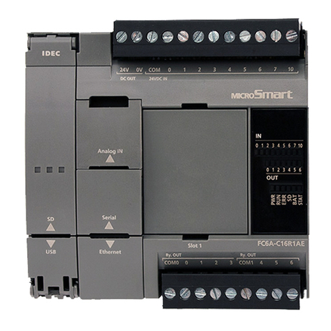
IDEC MICROSmart FC6A Series Owner's manual
IDEC
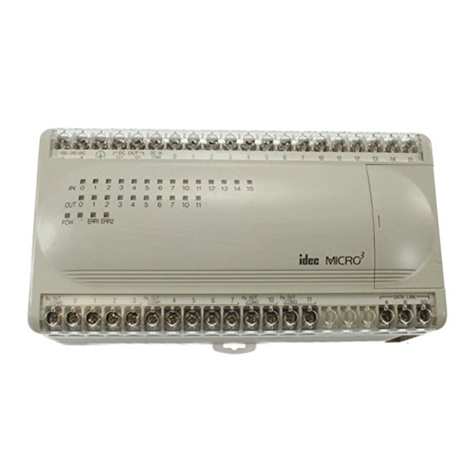
IDEC MICRO3C User manual
IDEC
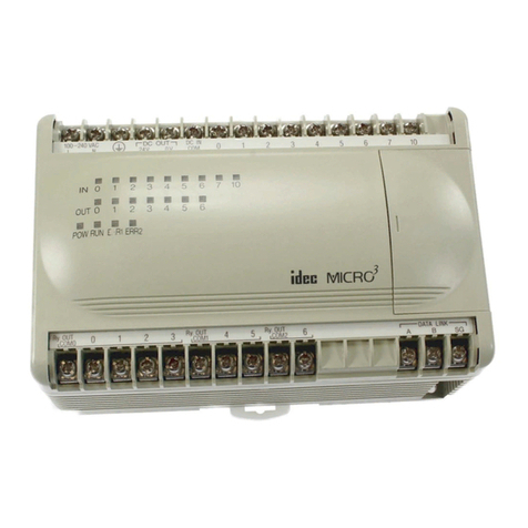
IDEC MICRO3 User manual
IDEC
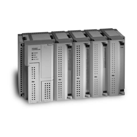
IDEC OpenNet series User manual
IDEC
IDEC SmartAXIS Touch FT1A Series User manual
IDEC
IDEC FS1A-C11S User manual
IDEC
IDEC SmartAXIS Touch FT1A Series User manual
IDEC
IDEC MICROSmart FC5A Series User manual
IDEC
IDEC SmartAXIS Touch FT1A Series User manual
IDEC
IDEC SE9Z-HC User manual
