Adafruit UDA1334A User manual

Adafruit I2S Stereo Decoder - UDA1334A
Created by lady ada
Last updated on 2019-01-30 06:56:56 PM UTC

2
4
7
7
7
8
8
10
10
14
15
15
17
17
18
19
21
23
23
23
23
23
23
25
25
25
27
30
30
30
33
33
33
36
39
39
41
41
42
43
45
45
45
Guide Contents
Guide Contents
Overview
Pinouts
Power Pins
I2S Pins
Audio Outputs
Optional Control Pins
Assembly
Installing Standard Headers
Raspberry Pi Wiring
Raspberry Pi Setup
Fast Install
Detailed Install
Update /etc/modprobe.d (if it exists)
Disable headphone audio (if it's set)
Create asound.conf file
Add Device Tree Overlay
Raspberry Pi Test
Speaker Tests!
Simple white noise speaker test
Simple WAV speaker test
Simple MP3 speaker test
Volume adjustment
Pi I2S Tweaks
Reducing popping
Step 1
Add software volume control
Play Audio with PyGame
Install PyGame
Run Demo
Arduino Wiring & Test
Wiring
Basic Test
DMA Test
CircuitPython Wiring & Test
Wiring
Code Examples
Tone Generation
Wave File
Where's my I2S?
Downloads
Files
Schematic & Fabrication Print
© Adafruit Industries https://learn.adafruit.com/adafruit-i2s-stereo-decoder-uda1334a Page 2 of 45

© Adafruit Industries https://learn.adafruit.com/adafruit-i2s-stereo-decoder-uda1334a Page 3 of 45
Overview
This fully-featured UDA1334A I2S Stereo DAC breakout is a perfect match for any I2S-output audio interface. It's
affordable but sounds great! The NXP UDA1334A is a jack-of-all-I2S-trades: you can use 3.3V - 5V logic levels (a rarity),
and can process multiple different formats by setting two pins to high or low. The DAC will process data immediately,
and give you a clear, analog, stereo line level output. It's even cool with MCLK-less I2S interfaces such as the
Raspberry Pi (which it's ideal for) - a built in PLL will generate the proper clock from the incoming signal.
© Adafruit Industries https://learn.adafruit.com/adafruit-i2s-stereo-decoder-uda1334a Page 4 of 45
For inputs, you can use classic I2S (the default) or 16-bit, 20-bit or 24-bit left justified data. You can set it up to take an
input system/master clock but we default-set it to just generate it for you, so you only need to connect Data In, Word
Select (Left/Right Clock) and Bit Clock lines. If you want, there's a mute pin and a de-emphasis filter you can turn on.
We put in plenty of ferrite beads, a low-dropout regulator, and the recommended band-pass filter so you get a very
nice clean output. With a sine-wave generator we swept through 20-20KHz and saw no attenuation or distortion. Plug
into either the 3.5mm stereo headphone jack or the breadboard-friendly pads. We think you'll be pleased with this
DAC!
© Adafruit Industries https://learn.adafruit.com/adafruit-i2s-stereo-decoder-uda1334a Page 5 of 45

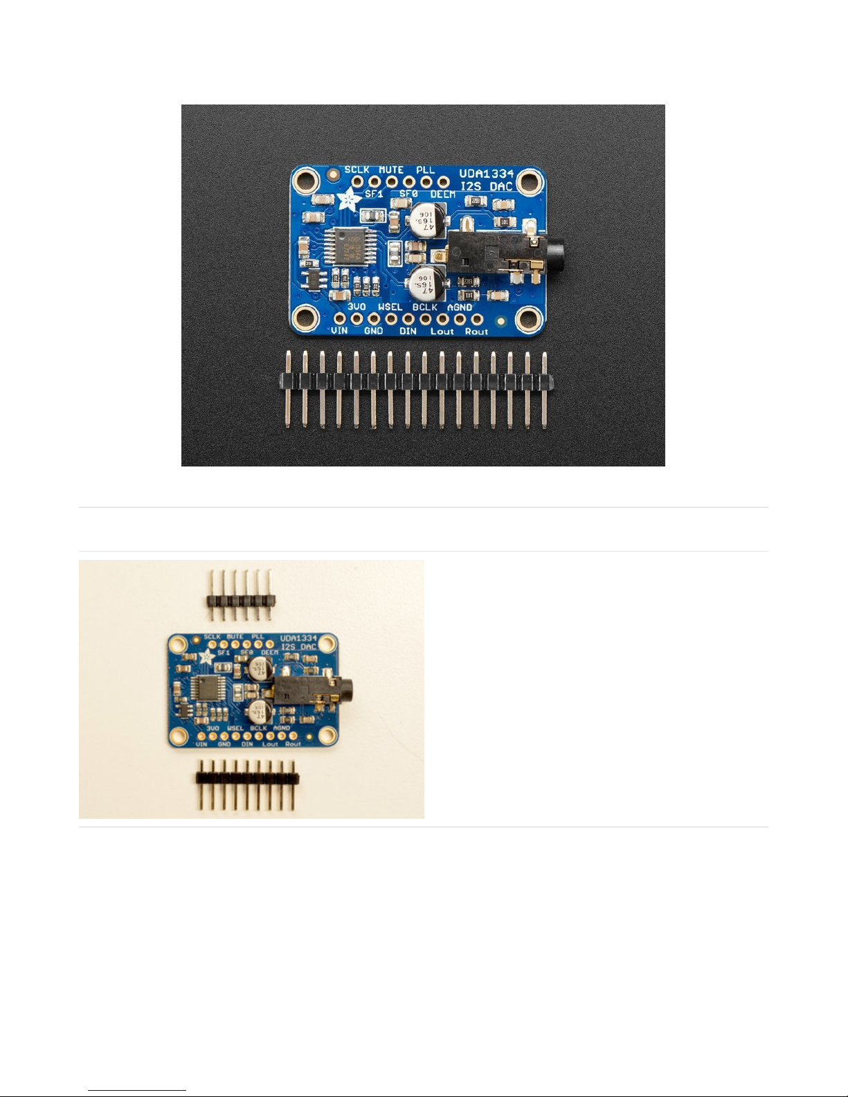
Each order comes with one I2S Stereo DAC breakout and some header you can solder on.
© Adafruit Industries https://learn.adafruit.com/adafruit-i2s-stereo-decoder-uda1334a Page 6 of 45

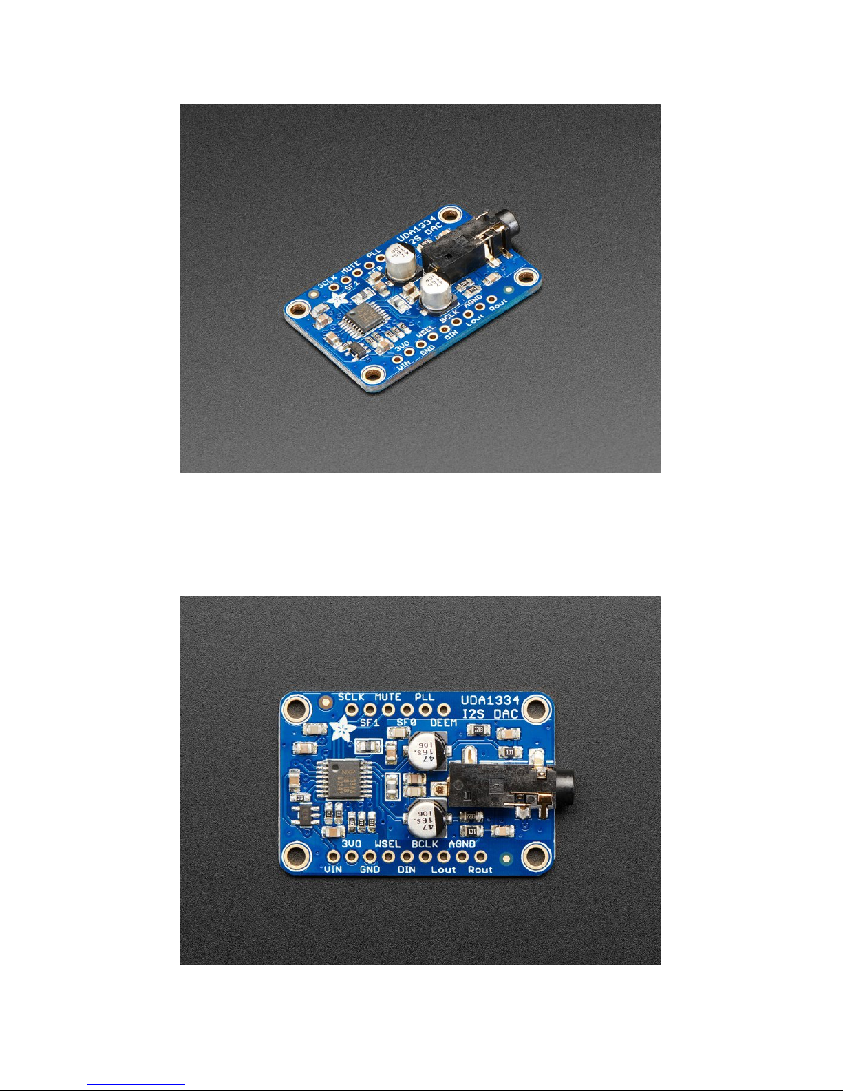
Pinouts
The UDA1334A is an I2S amplifier - it does not use analog inputs, it only has digital audio input support! Don't confuse
I2S with I2C, I2S is a sound protocol whereas I2C is for small amounts of data.
Power Pins
The UDA1334A requires 3.3V power but can take 3-5V
level logic on nearly all pins.
You can provide 3-5V power on the VIN pin and GND
and the built in regulator will generate a nice clean 3.3V
supplier on 3VOut.
Use the quietest power supply for Vin, we do filter the
power supply, but the quieter the better!
I2S Pins
© Adafruit Industries https://learn.adafruit.com/adafruit-i2s-stereo-decoder-uda1334a Page 7 of 45
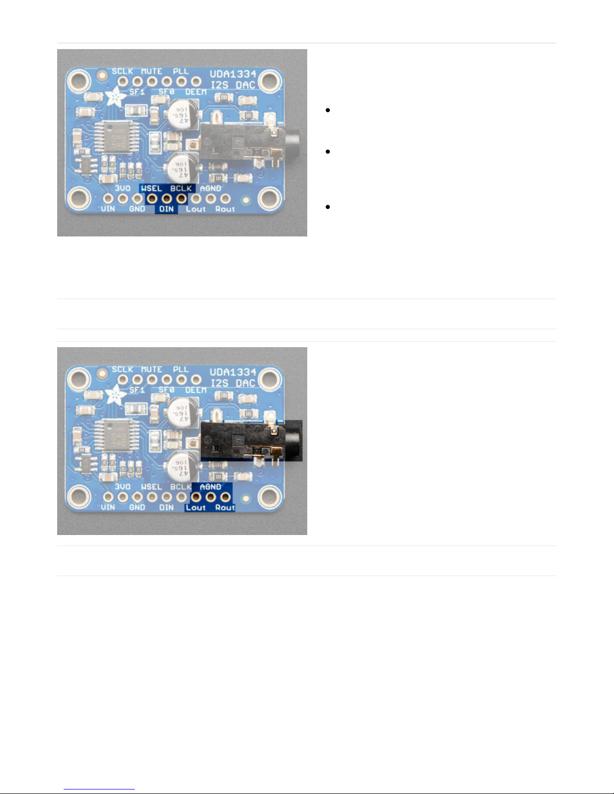
Three pins are used for stereo I2S data in. These pins
are required!
These can be 3.3-5V logic
WSEL (Word Select or Left/Right Clock) - this is the
pin that tells the DAC when the data is for the left
channel and when its for the right channel
DIN (Data In) - This is the pin that has the actual
data coming in, both left and right data are sent on
this pin, the WSEL pin indicates when left or right
is being transmitted
BCLK (Bit Clock) - This is the pin that tells the
amplifier when to read data on the data pin.
MCLK is not required to use this DAC, if you have an
MCLK pin on your audio source, leave it disconnected.
Audio Outputs
The exciting part! This is where your line level audio
comes out. We put big 47uF blocking capacitors on the
output so you can connect this to any stereo system.
AGND is a clean analog ground signal that we
recommend using as your analog reference, you'll get a
cleaner signal.
Note that this DAC was intended for use with a separate
amplifier and is rated for a 3 KΩ load. However, we've
found you
can
plug in 32Ω headphones and the output
is current-limited so it won't damage the DAC but you
will get distortions. (Powered headphones won't have
this issue)
Optional Control Pins
There are some extra configuration pins if you want to use them. They are not required for 99% of usage with an
Arduino or Teensy or Raspberry Pi. But you never know! So they are there for you. PLL and SF0 are 3.3V logic only,
the other pins are 3-5V safe.
Most of the pins have to do with changing the setup from audio mode to video mode. If you happen to want video-
mode, for synchronizing with NTSC/PAL, check the datasheet - we haven't used it for that purpose.
© Adafruit Industries https://learn.adafruit.com/adafruit-i2s-stereo-decoder-uda1334a Page 8 of 45

SCLK (Sys Clock) - Optional 27 MHz 'video mode'
ssytem clock input - by default we generate the
sysclock from the WS clock in 'audio mode' But
the UDA can also take a oscillator input on this pin
Mute - Setting this pin High will mute the output
De-Emphasis - In audio mode (which is the
default), can be used to add a de-emphasis filter.
In video mode, where the system clock is
generated from an oscillator, this is the clock
output.
PLL - sets the PLL mode, by default pulled low for
Audio. Can be pulled high or set to ~1.6V to set
PAL or NTSC video frequency
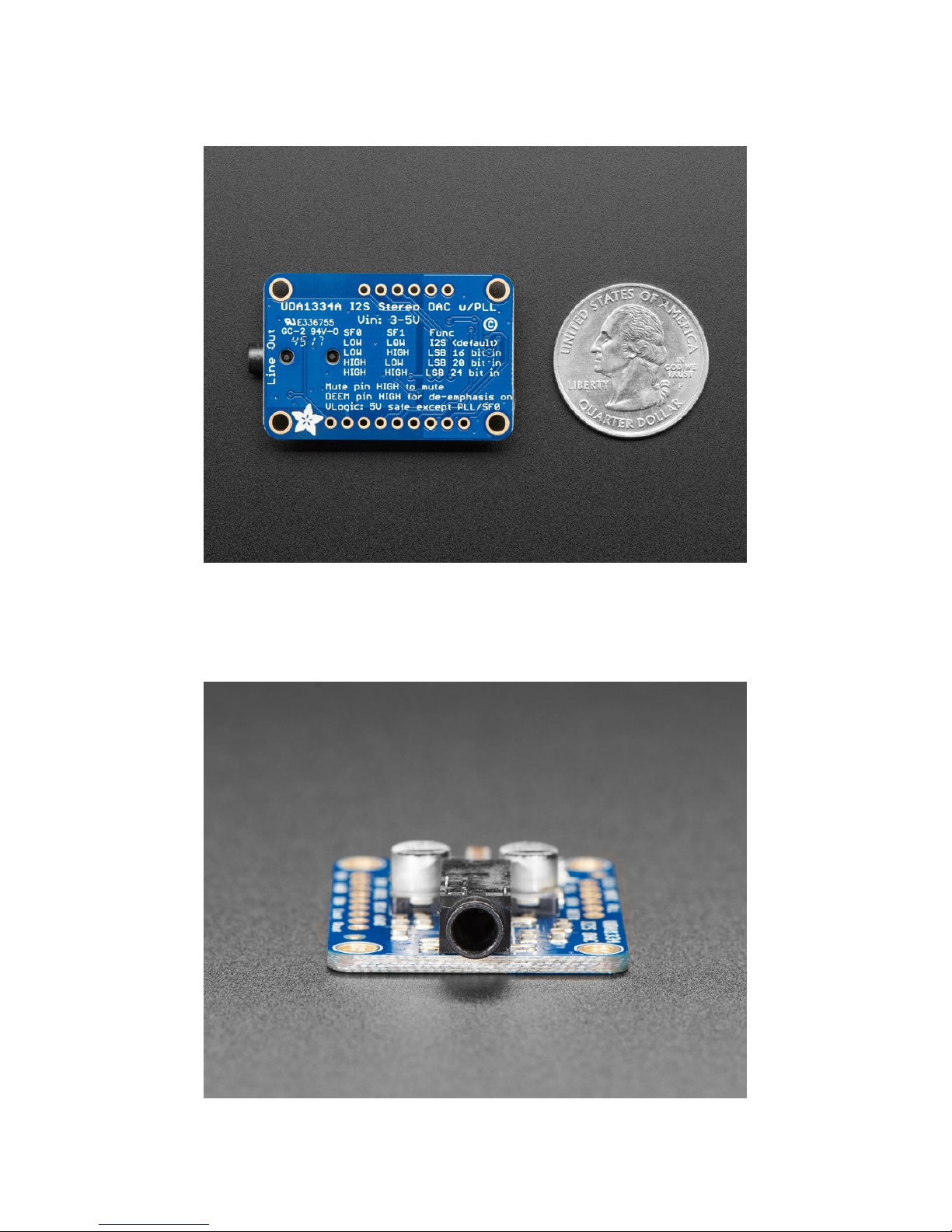
SF0 and SF1 are used to set the input data format. By
default both are pulled Low for I2S but you can change
them around for alternate formats.
See the back of the PCB for a quick reference
© Adafruit Industries https://learn.adafruit.com/adafruit-i2s-stereo-decoder-uda1334a Page 9 of 45
Assembly
Installing Standard Headers
The shield comes with 0.1" standard header.
Break apart the 0.1" header into 6 and 9-pin long pieces
and slip the short ends into the holes in the board
© Adafruit Industries https://learn.adafruit.com/adafruit-i2s-stereo-decoder-uda1334a Page 10 of 45

Make sure that all of the short parts of the header are
sticking through the two sets of pads on either side of
the board
Solder each one of the pins into the board to make a
secure connection
© Adafruit Industries https://learn.adafruit.com/adafruit-i2s-stereo-decoder-uda1334a Page 11 of 45

© Adafruit Industries https://learn.adafruit.com/adafruit-i2s-stereo-decoder-uda1334a Page 12 of 45

That's it! Move on to next page for wiring information
© Adafruit Industries https://learn.adafruit.com/adafruit-i2s-stereo-decoder-uda1334a Page 13 of 45

Raspberry Pi Wiring
if you have a Raspberry Pi and you want higher quality audio than the headphone jack can provide, I2S is a good
option! You only use 3 pins, and since its a pure-digital output, there can be less noise and interference.
This board works very well with boards that
don't
have audio like the Pi Zero and is the easiest way to get quality audio
out
Connect:
Amp Vin to Raspbery Pi 3V or 5V
Amp GND to Raspbery Pi GND
Amp DIN to Raspbery Pi #21
Amp BCLK to Raspbery Pi #18
Amp LRCLK to Raspbery Pi #19
https://adafru.it/A9T
https://adafru.it/A9T
This technique will work with any Raspberry Pi with the 2x20 connector. Older Pi 1's with a 2x13 connector do
not bring out the I2S pins as easily
© Adafruit Industries https://learn.adafruit.com/adafruit-i2s-stereo-decoder-uda1334a Page 14 of 45

Raspberry Pi Setup
Fast Install
Luckily its quite easy to install support for I2S DACs on Raspbian.
These instructions are totally cribbed from the PhatDAC instructions at the lovely folks at
Pimoroni! (https://adafru.it/nFy)
Run the following from your Raspberry Pi with Internet connectivity:
curl -sS https://raw.githubusercontent.com/adafruit/Raspberry-Pi-Installer-Scripts/master/i2samp.sh | bash
We've added an extra helper systemd script that will play quiet audio when the I2S peripheral isn't in use. This
removes popping when playback starts or stops. It uses a tiny amount of CPU time (on a Pi Zero, 5%, on a Pi 2 or 3 its
negligible). You don't need this on RetroPie because it never releases the I2S device, but it's great for Raspbian.
At this time, Raspbery Pi linux kernel does not support mono audio out of the I2S interface, you can only play
stereo, so any mono audio files may need conversion to stereo!
2017-11-2 Raspbian PIXEL ('full') has broken something in volume control. I2S works, but there's no software
volume setup, if you need this, try Raspbian Lite - will try to fix as soon as we figure out why :)
© Adafruit Industries https://learn.adafruit.com/adafruit-i2s-stereo-decoder-uda1334a Page 15 of 45
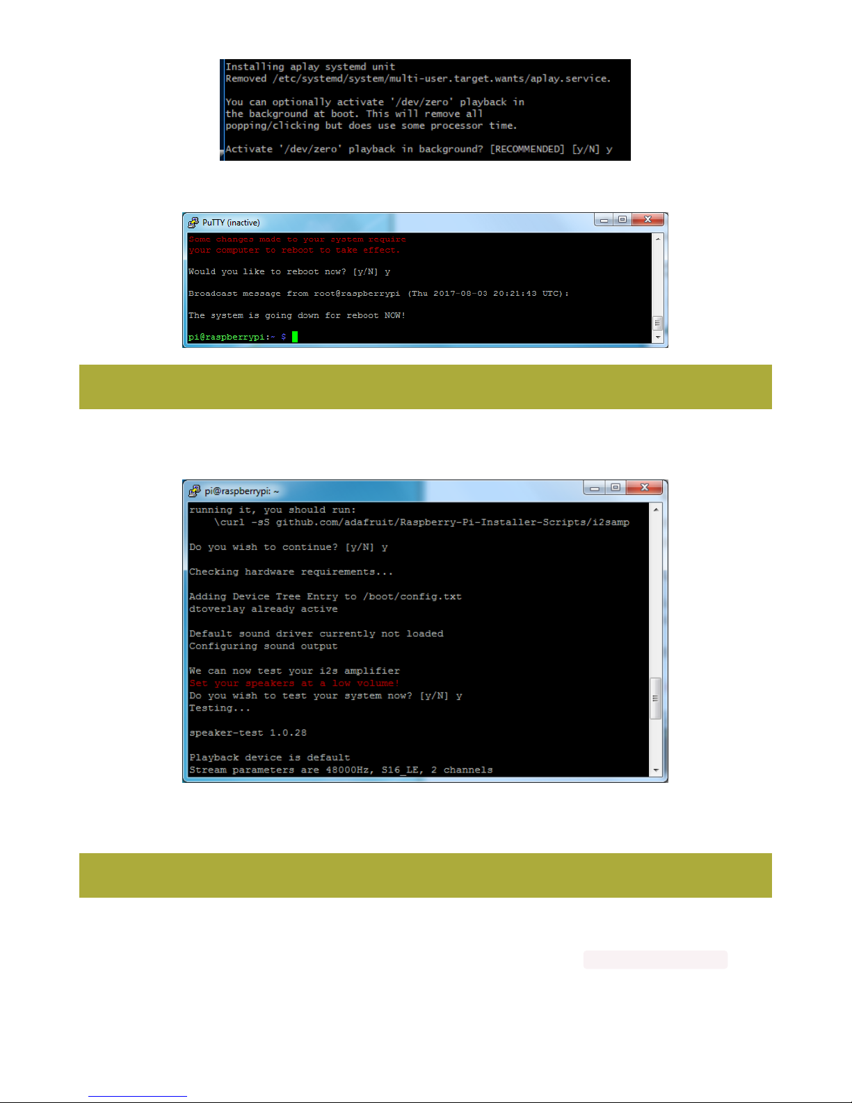
You will need to reboot once installed.
After rebooting, log back in and re-run the script again...It will ask you if you want to test the speaker. Say yes and
listen for audio to come out of your speakers...
If it sounds really distorted, it could be the volume is too high. However, in order to have volume control appear in
Raspbian desktop or Retropie you must reboot a second time after doing the speaker test, with sudo reboot
Once rebooted, try running alsamixer and use arrow keys to lower the volume, 50% is a good place to start.
If you're still having audio problems, try re-running the script and saying N (disable) the /dev/zero playback service .
You can then go to the next page on testing and optimizing your setup. Skip the rest of this page on Detailed
You must reboot to enable the speaker hardware!
You must reboot *twice* to enable alsamixer volume (really!)
© Adafruit Industries https://learn.adafruit.com/adafruit-i2s-stereo-decoder-uda1334a Page 16 of 45
Installation if the script worked for you!
Detailed Install
If, for some reason, you can't just run the script and you want to go through the install by hand - here's all the steps!
Update /etc/modprobe.d (if it exists)
Log into your Pi and get into a serial console (either via a console cable, the TV console, RXVT, or what have you)
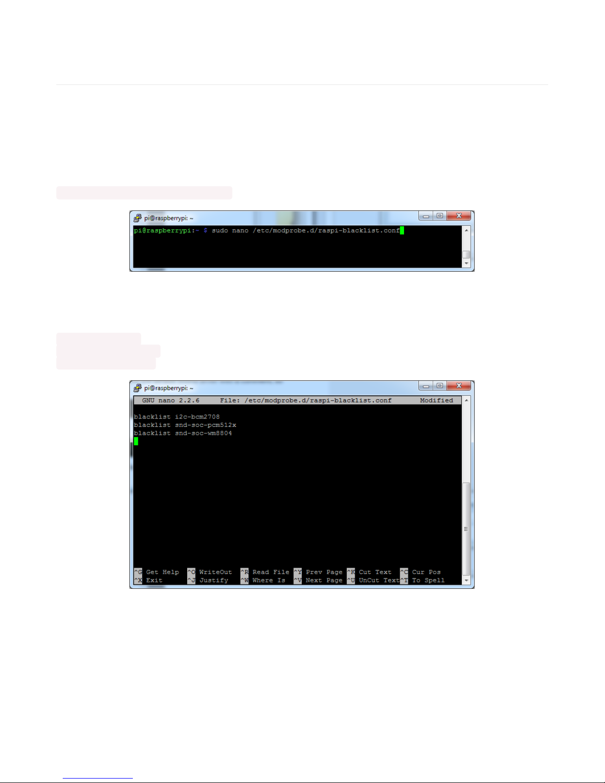
Edit the raspi blacklist with
sudo nano /etc/modprobe.d/raspi-blacklist.conf
If the file is empty, just skip this step
However, if you see the following lines:
blacklist i2c-bcm2708
blacklist snd-soc-pcm512x
blacklist snd-soc-wm8804
Update the lines by putting a # before each line
© Adafruit Industries https://learn.adafruit.com/adafruit-i2s-stereo-decoder-uda1334a Page 17 of 45
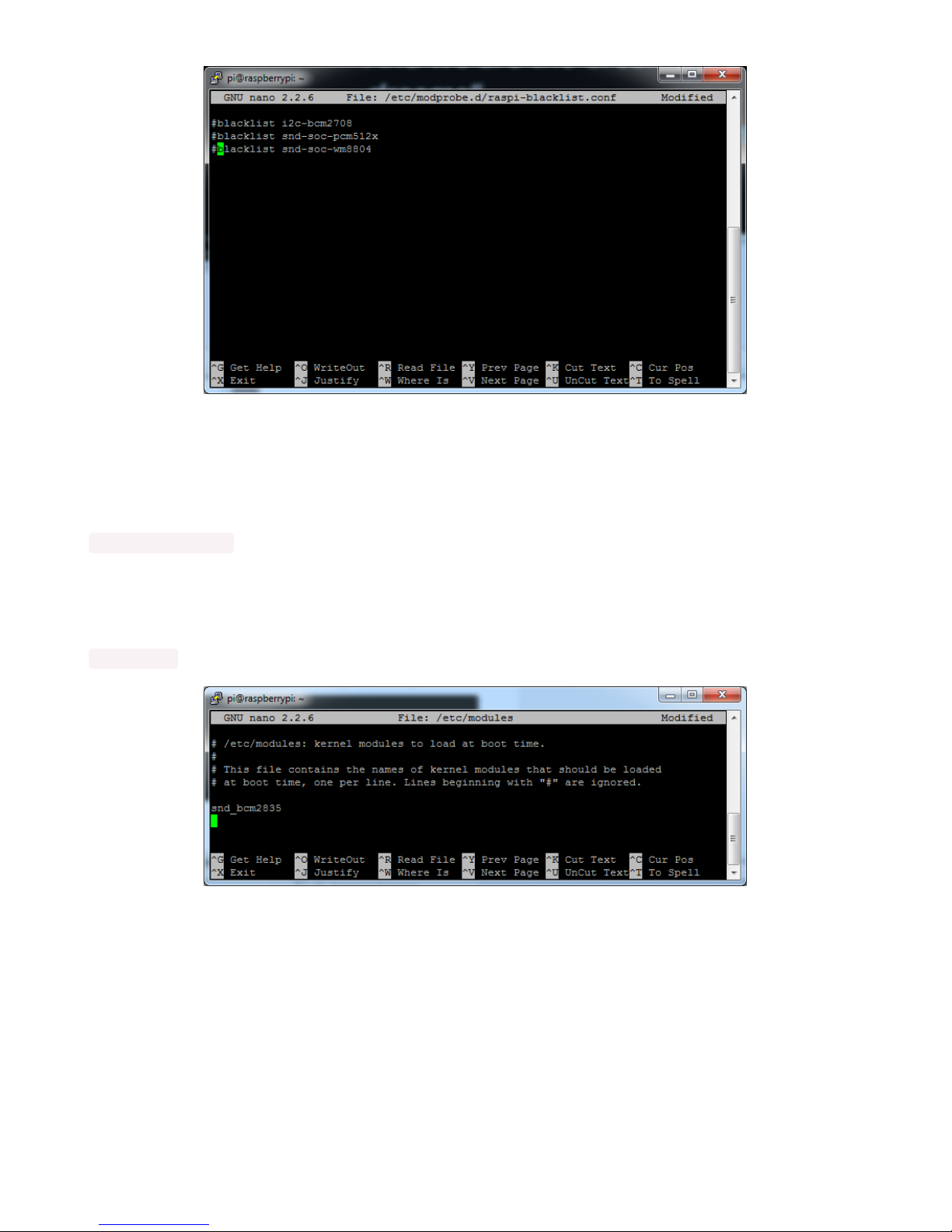
Save by typing Control-X Y <return>
Disable headphone audio (if it's set)
Edit the raspi modules list with
sudo nano /etc/modules
If the file is empty, just skip this step
However, if you see the following line:
snd_bcm2835
Put a # in front of it
© Adafruit Industries https://learn.adafruit.com/adafruit-i2s-stereo-decoder-uda1334a Page 18 of 45
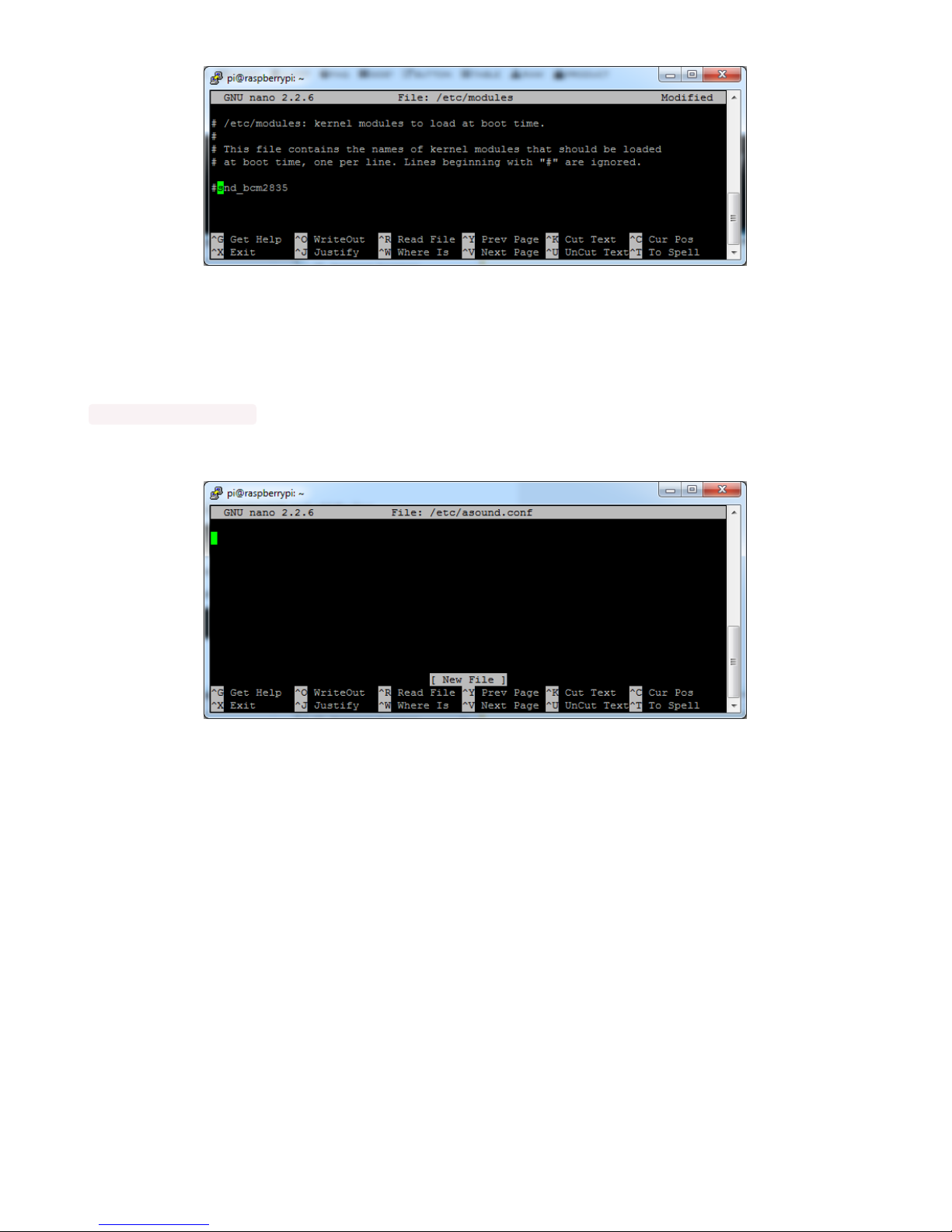
and save with Control-X Y <return>
Create asound.conf file
Edit the raspi modules list with
sudo nano /etc/asound.conf
This file ought to be blank!
Copy and paste the following text into the file
© Adafruit Industries https://learn.adafruit.com/adafruit-i2s-stereo-decoder-uda1334a Page 19 of 45

pcm.speakerbonnet {
type hw card 0
}
pcm.dmixer {
type dmix
ipc_key 1024
ipc_perm 0666
slave {
pcm "speakerbonnet"
period_time 0
period_size 1024
buffer_size 8192
rate 44100
channels 2
}
}
ctl.dmixer {
type hw card 0
}
pcm.softvol {
type softvol
slave.pcm "dmixer"
control.name "PCM"
control.card 0
}
ctl.softvol {
type hw card 0
}
pcm.!default {
type plug
slave.pcm "softvol"
}
© Adafruit Industries https://learn.adafruit.com/adafruit-i2s-stereo-decoder-uda1334a Page 20 of 45
Table of contents


