Adaptive Recognition Vidar User manual

Vidar Axle Counting Camera
Quick Installation Guide
Adaptive Recognition America
Adaptive Recognition Hungary
Adaptive Recognition Nordic
Adaptive Recognition Singapore
REQUESTINFO@ADAPTIVERECOGNITION.COM
WWW.ADAPTIVERECOGNITION.COM
1/21
0
Vidar Axle Counting Camera
Quick Installation Guide
This guide contains an overview of the hardware and required
components, suggested scenarios and step-by-step guide for installation,
and safety and maintenance instructions.
© Copyright Adaptive Recognition Inc.
All rights reserved.
05.12.2023.

Vidar Axle Counting Camera
Quick Installation Guide
Adaptive Recognition America
Adaptive Recognition Hungary
Adaptive Recognition Nordic
Adaptive Recognition Singapore
REQUESTINFO@ADAPTIVERECOGNITION.COM
WWW.ADAPTIVERECOGNITION.COM
2/21
0
VIDAR AXLE COUNTING CAMERA
Quick Installation Guide
Document version: 2023.12.05.
Table of Contents
1. Introduction ................................................................................................................................................3
2. Required components ..............................................................................................................................4
3. Hardware installation................................................................................................................................5
4. Camera Cable Layouts .............................................................................................................................9
5. External Illuminator Unit.........................................................................................................................10
6. Accessing the camera............................................................................................................................11
7. Date and time ...........................................................................................................................................11
8. Engine Manager.......................................................................................................................................12
9. Setup camera ...........................................................................................................................................14
9.1. Stream Settings...............................................................................................................................14
9.2. Optics.................................................................................................................................................16
9.3. Side Scan setup...............................................................................................................................17
9.4. Detection Area .................................................................................................................................18
9.5. Result.................................................................................................................................................19
10. Troubleshooting ..................................................................................................................................20
CONTACT INFORMATION..................................................................................................................................21

Vidar Axle Counting Camera
Quick Installation Guide
Adaptive Recognition America
Adaptive Recognition Hungary
Adaptive Recognition Nordic
Adaptive Recognition Singapore
REQUESTINFO@ADAPTIVERECOGNITION.COM
WWW.ADAPTIVERECOGNITION.COM
3/21
0
1. INTRODUCTION
The Vidar Axle Counting camera scans the vehicles from the side and generates laterally directed
events assembled from parts about the passing vehicles, on which additional engines can be run, for
example: VAC engine (Vehicle Axle Counting). The camera employs a lateral scanning approach,
generating comprehensive events that capture crucial details about passing vehicles. The Vehicle Axle
Counting (VAC) engine is instrumental in accurately counting the number of axles in passing vehicles.
Axle counting is critical to traffic management, providing valuable insights into traffic flow, vehicle
types, and overall road usage.
The lateral scanning mechanism of the Vidar camera distinguishes it from conventional surveillance
systems. Unlike traditional methods that focus on frontal or rear views, Vidar scans vehicles from the
side. This lateral perspective allows a more detailed and nuanced understanding of vehicle
characteristics.
After the proper settings, the following result can be achieved:

Vidar Axle Counting Camera
Quick Installation Guide
Adaptive Recognition America
Adaptive Recognition Hungary
Adaptive Recognition Nordic
Adaptive Recognition Singapore
REQUESTINFO@ADAPTIVERECOGNITION.COM
WWW.ADAPTIVERECOGNITION.COM
4/21
0
2. REQUIRED COMPONENTS
The box contains:
•Vidar Axle Counting Camera
•Bracket (COMBUY-OTH-0035)
Must have for camera operation:
•Power cable (EXPCAB-C01-0370-01)
•Ethernet cable (COMBUY-OTH-0440)
Required for camera operation: These are not included in the box, you can purchase them directly
from Adaptive Recognition:
•Synchronized External Illuminator with Cable and Bracket (850nm)
•GPIO / Illuminator cable (EXPCAB-C01-0479)

Vidar Axle Counting Camera
Quick Installation Guide
Adaptive Recognition America
Adaptive Recognition Hungary
Adaptive Recognition Nordic
Adaptive Recognition Singapore
REQUESTINFO@ADAPTIVERECOGNITION.COM
WWW.ADAPTIVERECOGNITION.COM
5/21
0
3. HARDWARE INSTALLATION
For reliable and efficient operation, selecting an optimal installation site is crucial.
Please refer to the example below for a recommended camera placement:
Image-Based Axle Counting with a Single, Intelligent Camera
Placement
Transversal
Overhead
Height
1.5 - 4 m
4 - 12m
Distance from object
3.5 - 8 m
3.5 - 8 m
Tilt
0°- 10°
40 - 65°
Roll
0° (max. +/- 1°)
0° (max. +/- 1°)
Vehicle speed range
0 km/h –120 km/h
0 km/h –120 km/h
Maximum number of lanes
1 or 2 with opposite side
1
Camera configuration
Vidar Smart 2xHDx (1C+1BW),
LT, Wide Zoom, IR+W panel,
AXLE COUNTING SW included,
extra IR850 recommended!
Vidar Smart 2xHDx (1C+1BW),
LT, Wide Zoom, IR+W panel,
AXLE COUNTING SW included,
extra IR850 recommended!
Illumination (optional white)
The recommended illumination
position is under the camera.
The ideal lighting angle is 30
degrees.
The recommended illumination
position is under the camera.
The ideal lighting angle is 30
degrees.
a) The camera has to be mounted in a horizontal position, do not rotate it in any direction!

Vidar Axle Counting Camera
Quick Installation Guide
Adaptive Recognition America
Adaptive Recognition Hungary
Adaptive Recognition Nordic
Adaptive Recognition Singapore
REQUESTINFO@ADAPTIVERECOGNITION.COM
WWW.ADAPTIVERECOGNITION.COM
6/21
0
b) The roll must be 0°. You can check the ROLL on the camera GUI here: (Maintenance > Sensors)
c) Connect the cables to the designated connectors. Seal the unused cable endings with end
sleeves before connecting to power!
d) Make sure the connecting cable does not lead rainwater drops into the camera housing!
e) Water may enter into the camera inside through not properly sealed connectors. To maintain
the camera’s watertightness, please ensure that connected cables are tightened properly and
the unused connectors are capped.
f) Failures due to inappropriate installation void the warranty, the accuracy and the whole
operational % might be decreased!

Vidar Axle Counting Camera
Quick Installation Guide
Adaptive Recognition America
Adaptive Recognition Hungary
Adaptive Recognition Nordic
Adaptive Recognition Singapore
REQUESTINFO@ADAPTIVERECOGNITION.COM
WWW.ADAPTIVERECOGNITION.COM
7/21
0
Overhead installation - - when the camera is placed above the lane:
•Installation height: 4 - 12 m
•Maximum tracking distance for detection: 3.5 - 8 meters
•The camera can capture the closer lane or the adjacent lane
•The tilt can be up to 65°
•If the camera is monitoring the adjacent lane, there might be an occlusion due to
passing vehicles
•Illuminator can be mounted under the camera with the same tilt
Offset from lane center [m] –(The calculated values are for a standard lane width of
3.5 meters.)
Camera [deg]
10
9
8
7
6
5
4
3
2
Camera
height
[m]
12
50
53
56
60
63
67
72
76
81
11
48
51
54
58
61
66
70
75
80
10
45
48
51
55
59
63
68
73
79
9
42
45
48
52
56
61
66
72
77
8
39
42
45
49
53
58
63
69
76
7
35
38
41
45
49
54
60
67
74
6
31
34
37
41
45
50
56
63
72
5
27
29
32
36
40
45
51
59
68
4
22
24
27
30
34
39
45
53
63

Vidar Axle Counting Camera
Quick Installation Guide
Adaptive Recognition America
Adaptive Recognition Hungary
Adaptive Recognition Nordic
Adaptive Recognition Singapore
REQUESTINFO@ADAPTIVERECOGNITION.COM
WWW.ADAPTIVERECOGNITION.COM
8/21
0
The angles and distances specified in the manual were determined based on realized and operational
projects. Deviation from these angles is reasonable within the limits of Adaptive Recognition
knowledge base.
In the case of extreme installation requirements, individual assessment is necessary.
If you have a location with different conditions, please do not hesitate to contact us for more
information!
Transversal installation - when the device is installed on a pole near the road and it has to
be:
•Install perpendicular to the road
•Maximum tracking distance for detection: 3.5 - 8 meters
•Installation height: 1.5 - 4 m
•The camera should always capture the closer lane
•It should not be tilted too much (max. 10°)
•The recommended installation height should always be at the lower limit, taking the
conditions into account
•Illuminator can be mounted under the camera with the same tilt

Vidar Axle Counting Camera
Quick Installation Guide
Adaptive Recognition America
Adaptive Recognition Hungary
Adaptive Recognition Nordic
Adaptive Recognition Singapore
REQUESTINFO@ADAPTIVERECOGNITION.COM
WWW.ADAPTIVERECOGNITION.COM
9/21
0
4. CAMERA CABLE LAYOUTS
Power:
4 pos. M12 Male
Ethernet:
(8 pos. M12 X coded, Female) ... ... RJ45

Vidar Axle Counting Camera
Quick Installation Guide
Adaptive Recognition America
Adaptive Recognition Hungary
Adaptive Recognition Nordic
Adaptive Recognition Singapore
REQUESTINFO@ADAPTIVERECOGNITION.COM
WWW.ADAPTIVERECOGNITION.COM
10/21
0
5. EXTERNAL ILLUMINATOR UNIT
There is a recommended option for an external illuminator, the wiring looks like this:
Connecting the 36V DC power supply should be done as per the below wiring diagram:
1. Connect Camera Power Cable black wires 1 and 2 to the power supply (V-).
2. Connect Camera Power Cable red wires 3 and 4 to the power supply (V+).
3. Connect the IR Power Cable black wire to power supply pin 5 (V-).
4. Connect the IR Power Cable red wire to power supply pin 7 (V+).
In the following section, we will demonstrate the proper setup of the camera.

Vidar Axle Counting Camera
Quick Installation Guide
Adaptive Recognition America
Adaptive Recognition Hungary
Adaptive Recognition Nordic
Adaptive Recognition Singapore
REQUESTINFO@ADAPTIVERECOGNITION.COM
WWW.ADAPTIVERECOGNITION.COM
11/21
0
6. ACCESSING THE CAMERA
•Ensure that the camera and the computer are connected to the same network.
•Enter an alternate IP address or set your computer’s IP in the 192.0.2.x subnet, where x is an
integer between 1 and 254 except 3. Set the subnet mask to 255.255.255.0.
Beside the fix IP configuration, you can use DHCP based network too.
•Start a browser then enter http://192.0.2.3 address into the address bar. This is the camera’s
default IP address. Further information on setting up the camera can be found in the Vidar
User Manual (Section 5).
7. DATE AND TIME
Current date and time and timekeeping settings are managed in the Date and Time section of the
camera web interface. Users have the option to set date and time manually, or use a time
synchronization protocol (NTP) which will keep time synchronized with a server over the network. For
further details, please refer to the Vidar User Manual (Section 5.2).

Vidar Axle Counting Camera
Quick Installation Guide
Adaptive Recognition America
Adaptive Recognition Hungary
Adaptive Recognition Nordic
Adaptive Recognition Singapore
REQUESTINFO@ADAPTIVERECOGNITION.COM
WWW.ADAPTIVERECOGNITION.COM
12/21
0
8. ENGINE MANAGER
This section allows the user to manage the Carmen ANPR engines and Hardware Key Licenses used
in the system.
This tool allows for installing, removing and configuring the Carmen ANPR engines used in the system.
The Install Engines tab lists the engines currently installed on the camera.
Unused engines can be removed with the “×” icon to the right. A new engine can be installed by clicking
on the + icon.
Currently used engines are listed in the Selected Engines tab.
•VAC engine should be installed on the camera

Vidar Axle Counting Camera
Quick Installation Guide
Adaptive Recognition America
Adaptive Recognition Hungary
Adaptive Recognition Nordic
Adaptive Recognition Singapore
REQUESTINFO@ADAPTIVERECOGNITION.COM
WWW.ADAPTIVERECOGNITION.COM
13/21
0
Hardware Key Licenses currently available in the device are listed in the License Manager section.
Additional licenses (sold separately) can be installed in the Upload License menu.
You should have already received your license file from your sales contact person which will enable
the latest recognition engines to run on your camera. If you do not already have your license, please
contact your salesperson or ATSS (open a new support ticket) to request that it be sent to you again.
This is important because the recognition engine you will install will only run if you also have the
correct updated license file uploaded into your camera.
The proper selection of engines is always based on licenses. Users should search for and download
the latest version containing the names.

Vidar Axle Counting Camera
Quick Installation Guide
Adaptive Recognition America
Adaptive Recognition Hungary
Adaptive Recognition Nordic
Adaptive Recognition Singapore
REQUESTINFO@ADAPTIVERECOGNITION.COM
WWW.ADAPTIVERECOGNITION.COM
14/21
0
9. SETUP CAMERA
9.1. STREAM SETTINGS
Next, Side scan setting needs to be turned on for Sensor #1 under the Stream settings.
A selector or drop-down menu will appear, always select Sensor #1.
At Sensor #1, select the highest frame rate from the drop-down menu next to the highest resolution.

Vidar Axle Counting Camera
Quick Installation Guide
Adaptive Recognition America
Adaptive Recognition Hungary
Adaptive Recognition Nordic
Adaptive Recognition Singapore
REQUESTINFO@ADAPTIVERECOGNITION.COM
WWW.ADAPTIVERECOGNITION.COM
15/21
0
With the Sidescan function is activated for Sensor #1, the user proceeds to the ANPR menu and
navigates to the ANPR settings submenu. Here, within the Processing stages sub-point, the VAC
function is selected. This step ensures that the camera is configured to accurately count axles in the
monitored zone.
To enable VAC option, you must enable Sidescan feature under Stream Settings
menu first.

Vidar Axle Counting Camera
Quick Installation Guide
Adaptive Recognition America
Adaptive Recognition Hungary
Adaptive Recognition Nordic
Adaptive Recognition Singapore
REQUESTINFO@ADAPTIVERECOGNITION.COM
WWW.ADAPTIVERECOGNITION.COM
16/21
0
9.2. OPTICS
The first step is to set the appropriate Zoom-Focus.
It needs to focus on having a zoom setting that includes the whole vehicle in the frame. The bottom
and top of the vehicle should be fully within the frame, and the image should start where the asphalt
(edge of the lane) begins. We can use the Auto Focus setting for a sharper and more accurate image.

Vidar Axle Counting Camera
Quick Installation Guide
Adaptive Recognition America
Adaptive Recognition Hungary
Adaptive Recognition Nordic
Adaptive Recognition Singapore
REQUESTINFO@ADAPTIVERECOGNITION.COM
WWW.ADAPTIVERECOGNITION.COM
17/21
0
9.3. SIDE SCAN SETUP
Go to the Live view menu, and select the Side Scan submenu. If the lane separator is not horizontal, it
is advisable to align it horizontally. If you notice any distortion in the image, use the MSQ and MQD
sliders to flatten the image.
MSQ: it adds or removes spherical distortion occurring within the main area of image.
MQD: it adds or removes spherical distortion occurring within the outer edge of image.
Rotate: align the picture horizontally.
In the Direction section, you can select which way the camera should measure. This also depends on
the installation location, it must be selected according to the specific environment. Always specify the
appropriate direction.
Reverse sign: Due to the two directions, one appears positively (e.g., moving to the right), while the
other appears negatively (e.g., moving to the left). If the user wants to see this reversed, it can swap
this sign.

Vidar Axle Counting Camera
Quick Installation Guide
Adaptive Recognition America
Adaptive Recognition Hungary
Adaptive Recognition Nordic
Adaptive Recognition Singapore
REQUESTINFO@ADAPTIVERECOGNITION.COM
WWW.ADAPTIVERECOGNITION.COM
18/21
0
9.4. DETECTION AREA
By pressing the Detection Area button, you can set the desired detection area on the image where the
vehicles pass entirely.
To achieve the best detection zone settings, the following considerations are needed:
•Exclude the sky, and avoid having too much space below. If you want to see the wheels, leave
a bit more space downward.
•It is more practical to focus on the wheels because, it cannot handle very homogeneous areas
(e.g., truck canvas).

Vidar Axle Counting Camera
Quick Installation Guide
Adaptive Recognition America
Adaptive Recognition Hungary
Adaptive Recognition Nordic
Adaptive Recognition Singapore
REQUESTINFO@ADAPTIVERECOGNITION.COM
WWW.ADAPTIVERECOGNITION.COM
19/21
0
9.5. RESULT
The results can be found in the ANPR Browse menu.
If you choose the info button , and in the Data group section, the VAC data will be shown, if
you choose it from the drop-down menu.
The displayed result on the image provides the number of axles, the total vehicle length, and the
distance between the axles.

Vidar Axle Counting Camera
Quick Installation Guide
Adaptive Recognition America
Adaptive Recognition Hungary
Adaptive Recognition Nordic
Adaptive Recognition Singapore
REQUESTINFO@ADAPTIVERECOGNITION.COM
WWW.ADAPTIVERECOGNITION.COM
20/21
0
10. TROUBLESHOOTING
Troubleshooting:
•The image is not sharp:
oThe correct configuration of the zoom and focus pairing is crucial to ensure
that the camera captures sharp, detailed images. The typical setting for zoom
is around 0, paired with the corresponding focus.
•Distortion in the image:
oThe image should be horizontal.
oUse the MSQ and MQD sliders to flatten the image.
•No events are being generated:
oActivate the Side scan function on Sensor 1 in the Stream Setting menu.
oInstall the VAC engine on the camera.
oActivate VAC processing stage on ANPR Settings menu.
oThe detection area is not set properly
Other manuals for Vidar
5
Table of contents
Other Adaptive Recognition Digital Camera manuals
Adaptive Recognition
Adaptive Recognition Vidar Container User manual
Adaptive Recognition
Adaptive Recognition Vidar User manual
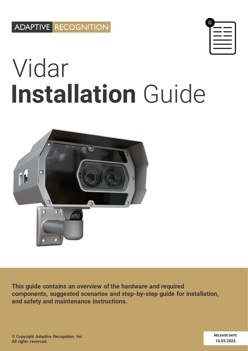
Adaptive Recognition
Adaptive Recognition Vidar User manual
Adaptive Recognition
Adaptive Recognition Einar User manual

Adaptive Recognition
Adaptive Recognition Vidar User manual
Adaptive Recognition
Adaptive Recognition Einar User manual
Adaptive Recognition
Adaptive Recognition S1 User manual
Adaptive Recognition
Adaptive Recognition Vidar Speed User manual

Adaptive Recognition
Adaptive Recognition Vidar User manual
