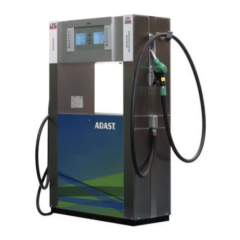
ADAST POPULAR LPG User manual

Adast Systems, a.s., 679 04 Adamov No. 496, Czech Republic
T+420 516 519 201, F+420 516 519 102, sales@adastsystems.cz
www.adastsystems.cz
OÚ/005/2005/A
XII/2016
USER´S MANUAL
Instructions for Operation, Maintenance
and Installation
LPG Dispenser for Dispensing of Liquiefied
Propane-butane
POPULAR LPG
MINOR LPG
V-line 899x.xxx/LPG


USER’S MANUAL V-line 899x.xxx/LPG
I
CONTENT
1. IMPORTANT NOTICE ................................................................................................... 1
2. USE 2
3. INSTRUCTIONS FOR THE SAFETY OF WORK ...................................................................... 2
3.1. Safety of the equipment design..............................................................................2
3.2. Operation safety ................................................................................................3
3.3. Ecological safety ................................................................................................3
3.4. Hygiene ...........................................................................................................3
3.5. Principles of the first aid......................................................................................3
4. DESCRIPTION ............................................................................................................ 4
4.1. Design of the dispensers.......................................................................................4
4.2. Skeleton ..........................................................................................................4
4.2.1. Case of the electronic counter ...............................................................................4
4.2.2. Case of the electronic counter –design 2017 (see fig.)..................................................4
4.3. Hydraulic system of the LPG fuel dispenser ...............................................................5
4.3.1. The hydraulic system of the fuel dispenser V-line 899x.xxx/LPG - piston volumetric flow meter
ADAST M 406.xxxx .......................................................................................................6
4.4. Electronics .......................................................................................................7
4.5. Communication to the control system ......................................................................8
4.6. Signalling of dispenser conditions (SO) .....................................................................8
4.7. Design with heating of the electronic case ................................................................8
5. TECHNICAL DATA....................................................................................................... 8
6. IDENTIFICATION ........................................................................................................ 9
6.1. Rating plate of the LPG fuel dispenser V-line 899x.xxx/LPG ..........................................9
7. FILLING OF LIQUEFIED GAS INTO MOTOR VEHICLES ...........................................................10
7.1. Dispensing with service ...................................................................................... 10
7.2. Self dispensing ................................................................................................ 11
7.3. Dispensing with preselection ............................................................................... 11
7.4. Description of the preselection function ................................................................. 12
8. FUNCTION OF KL-MANINF MANAGER KEYBOARD OR KL-SERINF ONE .....................................12
8.1. Manual setting of unit prices ............................................................................... 13
8.2. Setting of unit price values from the control system in AUTO mode ................................ 13
8.3. Displaying procedure of electronic totalizers for dispensers fitted with ADP1/T, ADP2/T,
ADP1/L electronic counter.................................................................................. 13
9. MAINTENANCE OF THE DISPENSER AND ITS INDIVIDUAL OPERATING UNITS..............................14
9.1. LPG piston flow meter ....................................................................................... 14
9.2. Differential valve ............................................................................................. 14
9.3. Separator....................................................................................................... 15
9.4. Electromagnetic two-stage valve .......................................................................... 15
9.5. Breakage coupling ............................................................................................ 15
9.6. Rupture coupling.............................................................................................. 15
9.7. LPG sight-glass ................................................................................................ 16

USER’S MANUAL V-line 899x.xxx/LPG
II
9.8. Dispensing hose ............................................................................................... 16
9.9. LPG dispensing nozzle ....................................................................................... 16
9.10. Dismantling of covers ........................................................................................ 16
9.11. Maintenance instructions for dispenser body parts..................................................... 17
9.12. Electronic counter............................................................................................ 18
10. DISASSEMBLY AND DISPOSAL ....................................................................................... 18
11. PRINCIPLES OF SERVICE INTERVENTIONS FOR LPG DISPENSER.............................................. 18
12. SUMMARY OF PRINCIPLES FOR INSPECTION OF LPG DISPENSER ............................................18
13. TRANSPORT ............................................................................................................19
14. DISPENSER INSTALLATION...........................................................................................19
14.1. Hydraulic section ............................................................................................. 19
14.2. Wiring........................................................................................................... 20
15. PUTTING OF THE DISPENSER INTO OPERATION.................................................................21
15.1. Putting of the dispenser and electronic counter into operation ..................................... 21
15.2. Shutdown of the dispenser and electronic counter..................................................... 21
15.3. Restart of the dispenser and electronic counter after power failure and voltage drop ......... 21
16. PACKING AND STORAGE .............................................................................................21
16.1. Packing ......................................................................................................... 21
1.1. Storage ......................................................................................................... 21
17. GUARANTEE AND RECLAMATION................................................................................... 21
18. SPARE PARTS CATALOGUE ..........................................................................................22
19. ACCESSORIES...........................................................................................................22
20. DOCUMENTATION DELIVERED ......................................................................................22
21. ENCLOSURES ........................................................................................................... 22

USER’S MANUAL V-line 899x.xxx/LPG
1
1. IMPORTANT NOTICE
This document is a guideline for the user how to proceed when installing, attending and maintaining the
dispenser. The information included in the present instructions are mandatory and the manufacturer does
not accept any responsibility for any damage due to their non-observance.
In the complex of the filling station, the dispenser is taken for a component of the dedicated gas
equipment subject to checks and revisions in the line of valid regulations anchored in the Filling station
operating regulation.
In the manufacturing plant, every dispenser is tested as to function, safety and metrology. User’s manual,
EC statement of a conformity and a service book with identification of the fuel dispenser components are
the parts of the dispenser delivery.
Dispensers are manufactured with high accuracy and care for the sake of their long term reliable and
safety operation. In time its operation it is necessary to keep primary safety codes, which first of all
protect the users before a possible accident and also the fuel dispenser before damage.
The dispenser has been designed for outdoor installation
Location/ Environmental class
Open/C
Machanical class
M 2 –with Beta Control ADPxxx electronic calculator
M 1 –with UNIDATAZ CDC electronic calculator
Elektromagnetická třída
E 2 - with Beta Control ADPxxx electronic calculator
E 1 –with UNIDATAZ CDC electronic calculator
Humidity
Condensing
ATTENTION!
The dispenser shall not be installed in an explosion danger zone 0, 1, 2 in compliance with
zones specified in the EN 60079-10-1!
Important instructions for installation and operation:
a) Prior to proceed to the dispenser handling, study these Operating User’s manual and other
manufacturer’s documents belonging to the dispenser accessories carefully.
b) Check the dispenser delivery for completeness and in the case of any discrepancy or damage, inform
supplier or the manufacturer without delay.
c) Ensure the proper storage of the dispenser in a dry and protected room for the pre-installing period.
d) Prior to installation, check the dispenser for the completeness of the filling station technology against
the valid project, and revise the connecting dimensions of the base frame including the outlet of the
piping system.
e) Rinse the technological equipment (piping systems) through the filtering device and continue rinsing
until the filtering device remains free of impurities.
f) With respect to operating safety it is necessary at dispenser installation situate with connection of
dispensing hose in the direction of exit from the filling station.
g) The dispenser requires the connection to the return piping of a DN 16 (1/2“) inner diameter.
h) Connect the dispenser electrical equipment and revise it.
i) Carry out the pressure test of the dispenser including its piping systems with a 2,5 MPa pressure and
revise it.
j) For putting the dispenser into operation, proceed in accordance with the point 16.
k) Carry out the test for proper function and entrust the metrological verification to a metrological
authority representative.
l) On meeting all of these requirements and after the approval by the representatives of the
metrological authority, the standard operation may start.
m) The servicing interventions should be entrusted to the properly trained personnel of the service firm
only.
SAVE FOR FUTHER USING!

USER’S MANUAL V-line 899x.xxx/LPG
2
2. USE
The liquid fuel dispensers of the V-line 899x.xxx/LPG series with an electronic counter ADP1/L, ADP1/T,
ADP2/T L of volume and price, alternatively mechanical counter of volume (for non-public dispensing)
described in the present manual have been designed for the dispensing of liquefied propane-butane (LPG).
The dispensing is made only by operating staff of the filling station (service mode).
They have been designed for the installation at road filling stations and a fleet of vehicles, etc. By means
of a communication line the dispensers are prepared for connecting to the control system and it is
possible operate this dispensers of self-service operation or serviced operation.
A gas leakage detector connected to the monitoring unit in the filling station booth can be installed in the
LPG dispenser for safe and ecological operation of the filling station.
This User´s manual serves the user to gain information on the design, correct attendance, maintenance
and safe installation.
3. INSTRUCTIONS FOR THE SAFETY OF WORK
The dispenser shows a clear indication to stop the engine and a maximum 80 % filling. The vehicle must be
ensured against a spontaneous move.
3.1. Safety of the equipment design
The manufacturer guarantees safety of the equipment design.
The dispenser design complies with the EN 14678-1 requirements and it is homologated for the
operation in environment specified by II2G IIAT3 symbols shown on the dispenser plate.
Considering operation safety in environs with explosion danger the dispensers have been EC –type
examination (certification) according to the annex III of the Directive 2014/34/EU –ATEX by an
authorised body FTZÚ, Pikartská 7, 716 07 Ostrava –Radvanice –Notified body no. 1026.
EC - Type Examination Certificate: No. FTZÚ 05 ATEX 0222
Regular inspection of production quality assurance according to supplement no. 4 to SO no. 23/2003
executes FTZÚ, s.p., Ostrava –Radvanice, NO no. 1026.
Notification of quality assurance: No. FTZÚ 02 ATEX Q 020.
Considering legal metrology the dispensers have been EC –type examination (certification) according
to the annex B of the Directive 2004/22/EC –MID by an authorised body Český metrologický institut,
Okružní 31, 638 00 Brno – Notified body no. 1383.
EC - Type Examination Certificate: No. TCM 141/07 - 4506
The producer performed a conformity examination for the fuel dispenser with the type described in
EC –Type Examination Certificate No. TCM 141/07 –4506 and technical requirements according to the
Directive of European Parliament and the Council 2004/22/EU.
The producer is competent for “The Declaration of Conformity” with the type based on production
quality assurance of measuring units according to the Directive Supplement D of European Parliament
and the Council 2004/22/EC.
Certificate of the Quality Management System for production, check-out and testing:
No. 0119-SJ-C007-07.
Regular inspection of production quality assurance, check-out and testing according to the Directive
Supplement D of European Parliament and the Council 2004/22/EC executes authorised body Český
metrologický institut, Okružní 31, 638 00 Brno – Notified body no. 1383.
ATTENTION!
Any handling open flame is prohibited during LPG filling and smoking is prohibited even in
vehicles interior. Also filling vehicle tanks with running motor and any other activities
possibly initiating explosion are prohibited!

USER’S MANUAL V-line 899x.xxx/LPG
3
3.2. Operation safety
Responsible for the filling station operation is the keeper who is bound to charge with the station
operation the properly trained and authorised personnel only with corresponding qualification. Duty of the
operators consists in filling the vehicle LPG pressure tanks in qualified way while respecting all safety
regulations, and in checking - in regular intervals - the dispenser and tank for proper conditions, the
mechanical equipment for proper run, gas pressure for proper level, and in keeping the prescribed
operational records.
Operator’s obligation:
–Keep the operated equipment in safety and proper conditions.
–Follow the filling station operating regulations and gas equipment operating instructions.
–Without delay report any defect, failure or irregularity arisen in the course of the gas equipment
operation to the keeper and, in case of a danger in delay, put the equipment out of operation
immediately.
–Keep the gas equipment clean and in order permanently and take care with avoiding the presence of
strangers close to the equipment.
–Without delay report the circumstances that make him more difficult the equipment operation
(sudden indisposition, for instance)
–Record the data on the beginning and the end of the work shift and the results of revisions made by
the operators and the extent of maintenance, repairs, checks and revisions performed.
–The dispenser and storage tank operators are not supposed to make any repairs of mechanical section,
and to alter the setting of any safety fittings.
3.3. Ecological safety
The dispenser space, where is the pumping mechanism, may be provided with gas leakage detectors (they
do not belong to the dispenser standard outfit) connected to the evaluating unit. In case some leak has
been detected (low concentration), the respective unit signals the leakage automatically and –in the case
of any danger - (higher concentration) puts the whole system out of operation immediately.
In the case of a small leak of gas, the filling station operators check the whole system and if they do not
detect any failure, ventilate the gas leaked (small leakage when connecting and disconnecting the
dispensing hose, effect of exhaust gases) and put the system into the operation again. In the case of a
higher concentration of leaked gas, the evaluating unit puts the electrical system out of operation. The
filling station operators shall put the station out of operation and report the defect to a specialised firm
that takes care of the repair.
3.4. Hygiene
From the point of view of hygiene, the dispensers are unobjectionable for the operators and the keeper.
For carrying out the routine maintenance and dispensing the liquefied propane-butane (LPG), it suits to
protect the hands with gloves.
3.5. Principles of the first aid
In the course of pumping avoid breathing in the propane-butane vapour because of the danger of
asphyxiation
Take the injured individual off the dangerous room to the fresh air. Take care with your own safety.
Be also aware of the danger of fire and explosion. Lay the injured individual comfortably, release his
cloths and leave it in absolute rest (he is not supposed to speak or walk). Call a doctor or take the
injured individual to a hospital. In the case of his dyspnoea or lack of breathing give him oxygen, or
apply artificial respiration.
In case the propane-butane contaminates the eyes, pour a bit of water on them, open the eye-lids
with care and rinse the eyes with plenty of running water (for about 15 min) and then look for
a medical care –injury of the cornea is imminent.
In case the skin gets in contact with the propane-butane, rinse the skin with plenty of water, take
off the cloths and shoes that have been contaminated with propane-butane (taking care with the risk
of fire and explosion) and rinse the attacked skin with running water (for about 15 min).
Do not chafe the chilblained skin, instead cover it with a sterile bandage!
In the case of a burn, it suits the cold the injury with cold water from water supply system
immediately (for about 15 min). Do not grease the injury with anything and visit a doctor. In case of

USER’S MANUAL V-line 899x.xxx/LPG
4
emergency apply sterile bandage exclusively or, in the case of large burns, wrap up the injured
individual into a clean bed sheet –do not take off the cloths! In case the cloths start burning, do not
run (because the flames would be fomented), extinguish with water, stifle the flames with a blanket –
jacket, by rolling on the ground. In case of being in the middle of fire, lie down immediately,
because the flame and gas getting the face, may origin lethal burning of breathing organs.
4. DESCRIPTION
4.1. Design of the dispensers
The dispensers ADAST POPULAR LPG is produced in two model lines:
V-line 899х.ххх/LPG - with a measuring unit ADAST LPG - piston positive displacement flow meter ADAST
M 406.xxхх
Type V - line
Number of hydraulics
Number of dispensing
places
Marking
8991.xxx/LPG
1
1
„MONO―
8992.xxx/LPG
2
4
„QUATTRO―
8993.xxx/LPG
1
2
„DUO―
8994.xxx/LPG
2
2
„DUPLEX―
8995.xxx/LPG
1
2
„DUO―
4.2. Skeleton
Skeleton –a self-supporting structure consisting of parts with high anticorrosive resistance. The base of
the dispenser is made of steel sheet, zinc-coated and varnished. Internal parts of the skeleton are made of
galvanised sheet. Parts of the body with the exception of the door of the hydraulic module and the
electronic counter case are made of stainless brushed sheet as a standard.
High resistance acrylurethane enamel is applied on the hydraulic module door and the electronic counter
case. The colour shade of the door including the logo can be optional.
Both doors are lockable; being unlocked, swing out and with earth wire disconnected they can be removed
and thus the hydraulic part is accessible. Connect the earth wires when the door is fitted back. A junction
box is built-in into the supporting column and is accessible after dismounting the side cover of the column.
4.2.1. Case of the electronic counter
A case of the electronic counter or ADAMAT electronics is bolted to the column. The counter case space is
closed with lockable covers. The covers are provided with transparent glass. Indicators with integrated
large-area display of dispensed volume, total price, price for one unit and unresetable electromechanical
total counters (totalizers) are connected from the case interior to the covers. The set of these elements
represents all necessary information for the customer.
The covers of the case are hung up on hinges enabling tilting upwards after unlocking and thereby easy
access in the case interior. The user’s local
preselection keyboard (if required) is located on the
case cover as well - an independent keyboard for
each dispensing point.
4.2.2. Case of the electronic counter –design
2017 (see fig.)
A case (1) of the electronic counter or ADAMAT
electronics is bolted to the hose module column.
The counter case space is closed with lockable
covers (2). The covers are provided with transparent
glass.
On the inside cover of the case is mounted under
glass large-area display (3) issued volume and total
price, which displays all necessary information for
the customer.

USER’S MANUAL V-line 899x.xxx/LPG
5
Above the display is placed IR sensor (5) for controlling and adjusting the dispenser calculator manager or
servicing keyboard.
On the outer side of the case cover is placed (optional) keyboard local user preferences (4) - an
independent keyboard for each dispensing point.
On request they can be built in a case unresetable electromechanical total counters –totalizers (6), which
are accessed by opening the cover.
ATTENTION!
Before opening the covers, it is always necessary to disconnect power to the dispenser and
perform a reliable hedge against its re-connection.
The dispensing nozzles are seated in covers in the „V― form pressed shape of the column. When the
dispenser is out of operation the dispensing nozzles in covers can be locked.
4.3. Hydraulic system of the LPG fuel dispenser
Poition
Hydraulics components LPG
1
Ball valve –supply pipe
2
Filter
3
Return valve liquid phase
4
Pressure release valve of the gas phase
5
Safety valve of gaseous phase
6
Hole in the safety valve
Supply piping
Return piping
Separator

USER’S MANUAL V-line 899x.xxx/LPG
6
7
LPG measurement unit
8
Differential valve
9
Electromagnetic valve
10
Manometer
11
Sight glass (optional)
12
Coupling safety (breaking or rupture coupling)
13
LPG Dispensing Hose
14
LPG dispensing nozzle
15
Ball valve metrological branch
16
Metrological branch
17
Electronic counter LPG
4.3.1. The hydraulic system of the fuel dispenser V-line 899x.xxx/LPG - piston volumetric
flow meter ADAST M 406.xxxx
Position
Hydraulics components LPG dispenser
1
Separator ADAST N 821.20/1, 821.20/1/ATC
2
LPG piston meter and an integrated
magnetic pulse transmitter M 406.xxP, M
406.xxP/1, M 406.xxЕP, M 406.xxЕP/1
3
Magnetic pulse transmitter ELTOMATIC
ME 01-05 or ME 01-05-05 or METRA MTX 075
or ADAST40
4
Differential valve ADAST V 860.20/LPG
5
Electromagnetic valve
6
Sight glass LPG –ADAST (optionally)
7
Snímač teploty LPG Pt 100 - ZPA
8
Manometer 0/25 bar
9
Ball valve G 1/2― metrological branch
In normal operation LPG is always in the liquid phase in the hydraulic system of the LPG dispenser.
A spherical cock (in the LPG piping) and a separator with a filter which forms one assembly unit with a
check valve of the liquid phase and pressure release valve and safety valve of gaseous phase are located
at the bottom of the fuel dispenser. A medium temperature resistance transmitter is connected to the
separator from the bottom for the dispensers designed with automatic temperature compensation of
dispensed volume in relation to its momentary temperature (ATC).
A metrological branch with a spherical cock G 1/2" for metrological verification and service purposes is
a part of the separator return piping.
A piston meter fitted with a sensor of impulses transmitted to the counter is connected to the separator
output through a pipe connection. The meter is fitted with pressure control valve keeping the medium in
the meter in liquid phase. The output from a differential valve is connected through an electromagnetic
valve to a sight-glass to which the dispensing hose with the dispensing nozzle is connected.
The dispensing hose is connected through safety breaking or rupture coupling.
The LPG being dispensed is supplied by a pump built-in in the storage tank area. At first the LPG flows
through the spherical cock and the filter into the separator. In case the liquid contains gaseous
components they should be separated and returned through the nozzle in the separator upper part and the
return piping which has to be open (if the dispenser is in operation) to the section of the storage tank that
contains the gaseous phase. The return piping internal diameter should be DN 16 mm (1/2") at least.
The gaseous phase space of the differential valve is connected to the return piping.
If required, the LPG dispenser can be fitted with a two-stage electromagnetic valve closing the LPG flow
during dispensing by means of preselection.

USER’S MANUAL V-line 899x.xxx/LPG
7
Meters LPG are supplied with optional integrated magnetic pulse transmitter Eltomatic ME 01-05
or ME 01-05-05 - type designation M 406.25P, M 403.32EP or with a magnetic pulse transmitter
METRA MTX 075 or ADAST 40 - type designation M 406.25P/1, M 406.25EP/1.
Meters with the designation of EP in electronic calibration, indicating P mechanical calibration
In the hydraulic system of the LPG dispenser during normal operation occurs always LPG in the liquid
phase.
4.4. Electronics
The dispenser control shall meet the exacting requirements of simplicity and convenience and depends on
the button pressing, alternativelly on the switch closure of LPG pump motor.
ADP1/T, ADP2/T, ADP1/L electronic counter of an up-to-date design with central processor board
equipped with a high efficient microprocessor. The configuration of the counter and its modes of
operation are adjusted by more than seventy parameters. The counter is provided with a self-diagnostic
system. The counter outlets control the motors, valves and signalling circuits. The electronic counter
processes the impulses coming from the impulse sensor and transmits them to the display, which displays
the dispensed volume, its price and a price per a volume unit. In case of power failure or voltage drop the
data displayed remain for 30 minutes at least.
Counters ADP1/T, ADP2/T, ADP1/L are standardly equipped for electronic meter calibration
(Electronic Calibration of Meters –EC) and per request by ATC –(Automatic Temperature
Compensation)
Electronic Calibration of Meters (EC) enable to correct measured volume by designed declination in
operation range -5,00 % to +5,00 % of recognised meter non accurancy by step of 0,05 %.
Automatic Temperature Compensation (ATC) is designed to compensate temperature expandity of
dispensed medium based on measured temperature during dispensing. For temperature measuring is used
approved certified temperature sensor –resistance temperature sensor PT 100, in the fuel dispensers V-
line 899x.xxx/LPG build in the separator N 821.20/ATC.
Calibration tablets for ATC on designed medium (type of fuel) can be integrated into SW of electronic
counter by customer request. Setting of calibration EC or ATC is provided by using of service keyboard KL-
SERINF and setting of proper calibrating switches DIP on body of electronics counter as per instructions
described in manual of electronic counters ADP1/T, ADP2/T, ADP1/L.
Providing of calibration is allowed to authorised person, only. The DIP calibration switches must be
fixed by plomb after calibration finish.
Displays: LCD type with BACK LIGHT illumination
LCD displays with BACK LIGHT (BLD) illumination are used especially for their good readability. The
duration of data holding on the display after supply voltage failure is 30 minutes at least. Decimal point on
BLD display devices is represented automatically in accordance with the setting of parameters.
Lighting
LED diodes are used for the illumination of displays at dispensers.
ON / OFF switching of the illumination is automatically carried out with the activation of electronics.
Totalizer: non-resettable electronic counter of dispensed volume and its price –11 digits –or non-
resettable electromechanical counter of dispensed volume –7 digits.
Electronic counter of ADP1/T, ADP2/T, ADP1/L series operates with a 2-channel impulse generator
producing 2x 100 impulses per 1 dm3. The HW and SW counters of the ADP1/T, ADP2/T, ADP1/L series
enable high metering accuracy and the application of the electronic calibration using the 2-channel
impulse generator.
The local electronic preselection system in IP67 design is integrated into the counter case. The
preselection enables the Customer’s preselection of the exact volume or the price of the product to be
dispensed. The two-stage electromagnetic valves ensure the closing of flow and exact dispensing of the
preselected volume / price and smooth initiation of dispensing.
The fuel dispensers can be equipped with ADAMAT paymant terminal (filling automatic equipment). This
equipment enables dispensing and payment of the product by means of contactless, magnetic and chip
cards including receipt printing. This equipment undertakes simultaneously all functions of the dispenser
electronic counter for non-public and public dispensing. The electronics of the filling automatic

USER’S MANUAL V-line 899x.xxx/LPG
8
equipment can be complemented by the ADP1/T, ADP2/T, ADP1/L electronic counter for public
dispensing.
The fuel dispenser is connected through a communication line to the control system, which controls the
operation of the whole filling station (releasing of dispensers, volume preselection, unit price variation,
self-diagnosis, etc.). The dispensers can be operated even at the filling stations without any control
system –i.e. in serviced operation.
Circuit diagrams for the connection of individual dispenser types to the switchboard of the filling station
are in enclosures.
4.5. Communication to the control system
The dispensers are equipped with ADP1/T, ADP2/T, ADP1/L electronic counters, which are able to
communicate to POS Win control systems. A communication serial interface RS 485 or a communication
standard IFSF LON are used for the communication of electronic counters to the superior control system.
Communication to different control systems shall be consulted with the manufacturer of the dispensers in
advance.
The fuel dispensers connected to the control system can be operated in the mode of volume preselection
or the financial sum preselection from the control system (the dispensers have to be equipped with two-
stage or proportional electromagnetic valves).
The POSWIN control system (POS Win EURO) enables the process control and the sale of goods according
to stock cards (999 999 items in 99 groups) including storage facilities. The control systems communicate
with the dispenser on the principle of the bus interface RS 485. They combine the basic functions of the
filling station, i.e. sale of fuels, sale of dry goods and their filing. The POS system is also able to operate
even as a multi-cash one, i.e. its individual parts can be interconnected in the communication SW
network, two backoffices and three tills, if more than five backoffices or tills are connected, a server has
to be included.
4.6. Signalling of dispenser conditions (SO)
On Client’s special requirement the fuel dispenser can be equipped with a red signal light, which gives
information to the customer and the operator about the present dispenser condition –the dispenser is
blocked or ready for fuel filling.
4.7. Design with heating of the electronic case
On the special customer´s requirement the fuel dispenser can be delivered with heating of electronic case
by heater 250 VA. For feeding of the heating is used an individual cable - see the enclosure no.14.
5. TECHNICAL DATA
5.1. Basic parameters
Dispensed liquid
Liquefied propane butane (LPG)
Electronic counter
ADP1/T, ADP2/T, ADP1/L
Display
illuminated LCD - BACK LIGHT DISPLAY (BLD)
Power supply of electronics
Unap
Pnap
1/N/PE AC 230 V ± 15 %, 50 Hz
input 85 VA
Power supply of electronic case
heating
Unap
Pnap
1/N/PE AC 230 V ± 15 %, 50 Hz
input 250 VA
Volume displayed
6 digits with the setting of digit position
Price displayed
6 digits with the setting of digit position
Unit price displayed
4 digits with the setting of digit position
Total volume counter
electromechanical - 7 digits
electronically - 11 digits
Number of impulses per 1 dm3
100
Basic sensed unit
0,01 dm3
Permissible deviation of sensed volume
+/-1 impulse, i.e. 0,01 dm3
Max. flow rate Qmax
40 dm3.min-1
Min. flow rate Qmin
8 dm3.min-1
Min. measured quantity (MMQ)
5 dm3
Accuracy of measurement
±0,5 %
Max. operating pressure pmax
1,8 MPa

USER’S MANUAL V-line 899x.xxx/LPG
9
Min. operating pressure pmin
0,7 MPa
Ambient operating temperature
standard -20 °C to +50 °C;
special -40 °C to +55 °C / -40 °C to +60 °C
Liquid temperature
-20 °C to + 50 °C
Filtering property
10 µm
Reach of dispensing hose
4 to 7 m
Max. level of noise
<60 dB
Required inner diameter of feeding piping
DN 19 –inner thread G 3/4― ISO 228 – G ¾―
Required inner diameter of return piping
DN 16 –inner thread G 1/2― ISO 228 – G ½―
Communication interface
RS 485; IFSF –LON, TCP/IP (Ethernet)
Average operating period of a repair
too = 25 min
Average service life
tz= 5 years
5.2. Technical parameters of the fuel dispenser LPG MONO
V-line 8991.6x2/LPG; M
V-line 8991.6x3/LPG; M
V-line 8991.614/LPG
Max. flow rate Qmax
40 dm3.min-1
Min. flow rate Qmin
8 dm3.min-1
Operating flow rate by dispensing from one nozzle Q
40 dm3.min-1
Min. measured quantity (MMQ)
5 dm3
5.3. Technical parameters of the fuel dispenser LPG DUO and QUATTRO
V-line 8992.6x2/LPG; M
V-line 8993.6x2/LPG; M
V-line 8995.6x2/LPG; M
Max. flow rate Qmax
40 dm3.min-1
Min. flow rate Qmin
8 dm3.min-1
Max. flow rate Q dispensed from one nozzle
40 dm3.min-1
Operating flow rate by dispensing from both nozzles - DUO Q
2 x 30 dm3.min-1
Operating flow rate by dispensing from four nozzles - QATTRO Q
4 x 30 dm3.min-1
Min. measured quantity (MMQ)
5 dm3
5.4. Technical parameters of the fuel dispenser LPG
DUPLEX
V-line 8994.6x2/LPG
Max. flow rate Qmax
40 dm3.min-1
Min. flow rate Qmin
8 dm3.min-1
Operating flow rate by dispensing from both nozzles Q
2 x 40 dm3.min-1
Min. measured quantity (MMQ)
5 dm3
6. IDENTIFICATION
6.1. Rating plate of the LPG fuel dispenser V-line 899x.xxx/LPG
1.
Measuring device manufacturer and address
Adast Systems, a.s., CZ –679 04 Adamov 496
2.
Name of measuring device
LPG dispenser
3.
CE marking with the number of the Notified body
coopreated in the conformity Assessment and
supplementary metrology marking M(xx –year of
verification of the dispenser)
4.
Type
See enclosure 22 and 23
5.
Number of EC –type examination certificate - M
TCM 141/07 –4506
6.
Accuracy class
1,0
7.
Serial number and year of manufacture
xxxx/xx - according to dispensers
manufacturer files
8.
Ambient temperature range –TAmb [°C]
Ambient operating temperature –according to
version of the fuel dispenser

USER’S MANUAL V-line 899x.xxx/LPG
10
9.
Liquid temperature range –TLiq [°C]
–20 to +50 [°C]
10.
Mechanical class
M 2
11.
Electromagnetic class
E 2
12.
Liquid
LPG
13.
Maximum flowrate
Qmax [L/min]
14.
Minimum flowrate
Qmin [L/min]
15.
Minimum measured quantity
MMQ [L]
16.
Maximum pressure
pmax [bar]
17.
Minimum pressure
pmin [bar]
18.
Number of EC –type examination certificate - Ex
FTZÚ 06 ATEX 0222
19.
CE marking with the number of the Notified body
coopreated in the conformity assessment
20.
Specific marking for the explosion protection
including the symbol of the group and category of
the device, explosion and temperature categories
of dispensed fuels
II2G IIAT3
21.
Standard for fuel dispensers
EN 14678-1
22.
Electrical parameters
Values of electronics, heating and el. motors
feeding
7. FILLING OF LIQUEFIED GAS INTO MOTOR VEHICLES
The construction of dispenser meets the high requirements of simplicity and comfort commissioning by
pressing a button or turning on the switch of the pump motor.
Controlling of the dispenser V-line 899x.xxx/LPG
1
STOP switch
2
Switch
3
Control Button –„SAFETY KEY DEAD MAN―
7.1. Dispensing with service
1. The operator controls the movement of vehicles within the liquefied gas filling area so that the
dispensing hose reaches the fuel tank filler of the vehicle.
1
2
3

USER’S MANUAL V-line 899x.xxx/LPG
11
2. Then he checks the connection to the filler of the storage tank which is led to the vehicle surface,
the type of the vehicle fuel tank filler and decides either for direct connection of the dispensing
nozzle to the filler of for the use of an adapter for different types of vehicle fillers. The operator
checks visually the condition and the wear of the filler which could result in gas leakage from the
vehicle. He performs smell test to identify prospective gas leakage from the vehicle. In case he
identifies any serious deficiencies, he has to refuse to fill the vehicle and recommends the
customer to visit an authorised service shop which can remedy the defects detected.
3. After connecting the dispensing nozzle to the vehicle filler the operator shall check the
connection and then pressing the button (3) or switch (2) on the dispenser to "ON" position resets
the counter automatically. After resetting the pump motor is started. The filling can be stopped
at any time by releasing the button (3) or switching to "OFF" position.
4. After filling and releasing the push-button or switch to "OFF" position, the dispensing nozzle is
disconnected from the vehicle tank and hung up.
ATTENTION!
In case of gas leakage or any danger the operator stops the filling!
IMPORTANT WARNING:
In case the tank is filled to be full (most frequent case) the automatic safety level
regulation controlling the filling of the tank to 80 % max. shuts off the supply by means of
a mechanical limiter without respect to manual push-button control.
7.2. Self dispensing
ATTENTION!
Dispenser for self-service must be within the meaning of Article. no. 4.5.8 EN 14678-1
provided with a means ensuring an that the filling process can start and maintain only
PRESS OF BUTTON A DEAD MAN! By releasing this button must flow LPG immediately
conclude!
1. Attach the dispensing nozzle to the filling end of the vehicle tank and check the connection.
2. After connecting the dispensing nozzle to the vehicle filler the operator shall check the
connection and then pressing the button (3) resets the counter automatically. After resetting the
pump motor is started. The filling can be stopped at any time by releasing the button (3).
3. After filling and releasing the push-button, the dispensing nozzle is disconnected from the vehicle
tank and hung up.
ATTENTION!
In the event of a gas leak or danger immediately stop pumping!
IMPORTANT WARNING:
In case the tank is filled to be full (most frequent case) the automatic safety level
regulation controlling the filling of the tank to 80 % max. shuts off the supply by means of
a mechanical limiter without respect to manual push-button control.
7.3. Dispensing with preselection
Such filling is only possible with dispensers equipped with
local preselection.

USER’S MANUAL V-line 899x.xxx/LPG
12
7.4. Description of the preselection function
The selection of the required value of fuel to be dispensed is carried out with the switch for pump
motor start in the position OFF (0)!
1. Connect the dispensing nozzle to the fuelling ending of the vehicle tank.
2.a) Preselect the required quantity to be dispensed according to the price by keys identified 5 and 10
in arbitrary sequence up to the amount of money level. The preselected quantity to be dispensed is
displayed on the price display. In case of invalid option deselect it by the "RESET"key.
2.b) Preselect the required quantity to be dispensed according the volume by keys identified 5 litres and
10 litres in arbitrary sequence up to the required volume level. The preselected volume to be
dispensed is displayed on the volume display. In case of invalid option deselect it by the "RESET"
key.
3. The display is reset by pressing down or switching the control switch to the position ON (I), the
dispenser is started and filling can be carried out up to the preselected price or volume when
dispensing is automatically stopped.
4. After stopping the LPG filling by means of the push-button, release or switching over the switch
to "OFF" (0) position, disconnect the dispensing nozzle from the vehicle filler and hang it up into
the cover.
ATTENTION!
In the event of a gas leak or danger immediately stop pumping!
IMPORTANT WARNING:
When filling the tank to 80% capacity cut off the mechanical limiter, and regardless of the
manual control button or switch.
In case the tank is filled to be full (most frequent case) the automatic safety level
regulation controlling the filling of the tank to 80 % max. shuts off the supply by means of
a mechanical limiter without respect to manual push-button control.
Non-dispensed preselected volume is reset after 20 seconds approximately.
8. FUNCTION OF KL-MANINF MANAGER KEYBOARD
OR KL-SERINF ONE
The KL-MANINF manager keyboard and the KL-SERINF service keyboard are delivered as a design with
infrared wireless transmission IR.
IR KL-MANINF manager keyboard
The keyboard enables the setting of unit prices and the situation display of electronic totalizers.
The manager keyboard is equipped with four keys marked „0―, „+― and „-― (the „R― is not used). The
„0― key is used for the transition to the "setting of unit prices for MAN" and for the termination of any
function executed on the manager keyboard.
The „+― and „-― keys are used for proper setting of the unit price values or for the transition to the mode
of "situation display of electronic totalizers".
IR KL-SERINF service keyboard
The keyboard enables the counter setting and the keying of values for electronic calibration of meters and
ATC, the situation display of electronic totalizers, setting of unit prices and setting the vapour exhaust
recovery.
The service keyboard is fitted with four keys, „0―, „+―„-― as a standard and the "S" key as an extra key.
The "S" key is used for the transition to the mode of "the data setting / calibration".
If the "S" key is not used, the service keyboard can be used for all functions controlled by the manager
keyboard and the keying is identical with that of the manager keyboard.
N. B.
If the nozzle has been lifted at least once since the last activation of the counter, the transition to the
setting of unit prices is not executed in the MAN mode. The transition to the setting is also not executed

USER’S MANUAL V-line 899x.xxx/LPG
13
even in case the nozzle has been either hung up again without fuel dispensing or previous transaction has
not been deactivated by means of RLS entry.
8.1. Manual setting of unit prices
Necessary conditions for the transition to the setting of unit prices
–MAN mode of operation
–the nozzle has not been lifted since the last activation of the counter
–transaction executed shall be acknowledged (deactivation by means of RLS entries).
In the MAN mode the unit prices of fuel product are set by means of the KL-MANINF manager keyboard or
the KL-SERINF service keyboard.
1. The user can enter the setting mode of unit prices by depressing the „0― key.
2. In the setting mode of unit prices
- the number of side for which the unit price is being set ("1" ... A side, "2" ... B side) is displayed
on the first line of displays (i.e. on the line of total price)
- the number of nozzle for which the unit price is being set is displayed on the second line of
displays (i.e. the line of total volume)
- on the third line of displays the digit, the value of which is being set by the user, is flashing (e.g.
on the line of unit price)
3. The user
- raises the numerical value of the digit actually set by the "+" key(i.e. the flashing one), (digit 9
passes into 0), by depressing the "+" key we can list through 0-9 values - i.e. the autorepeat
function
- shifts the digit setting to higher digit positions by means of the "-" key
- shifts the setting from the highest position of the product unit price to the lowest digit position
of the product unit price of the next nozzle by means of the "-" key
4. In this way the user can set successively the price values for all nozzles on the A side, then B side (if
it exists and the products on this side differ in price).
5. Whenever the user can terminate the setting of the unit price values by depressing the „0― key.
6. Now the unit price values have been written in non-volatile storage in this way and the counter sets
the MAN mode.
8.2. Setting of unit price values from the control system in AUTO mode
In AUTO mode the unit price values are set from the control system for all transactions independently on
unit price values set for the MAN mode.
The unit price values for the AUTO mode are set for all dispensing points by dynamic statement
(command) "permission to dispense" transmitted from the filling station console or by the "price setting"
statement. All these statements are a part of the specification of the EASYCALL communication protocol.
8.3. Displaying procedure of electronic totalizers for dispensers fitted with
ADP1/T, ADP2/T, ADP1/L electronic counter
The ADP1/T, ADP2/T, ADP1/L counter is fitted with non-resettle electronic totalizers of volume and price
for individual dispensing nozzles.
The totalizers can be displayed on the displays of the side by means of the KL-MANINF manager keyboard.
The display of the totalizer can be switched by lifting the relevant nozzle or by switching the LPG switch.
The sum of the volume (or the sum of the price) is displayed on the displays of the side on the coupled
lines of the total price and total volume. Both displays of the side display an identical sum, as the first
from the left "U" character is displayed on the total price line for the display of the volume sum and
"A" character for the display of the price sum.
The second character from the left displays the highest digit position of the relevant sum, the sixth
character from the left displays the lowest digit position of the relevant sum.
The side number and the nozzle number of the totalizer displayed at this moment are displayed on the
unit price line:
e.g..: 1 - 1...A side - nozzle No. 1;
2 - 1...B side - nozzle No. 1.
Display procedure:

USER’S MANUAL V-line 899x.xxx/LPG
14
1. Both dispensing points shall be free (transitions are not running at any of the both points and
terminated transactions shall be acknowledged).
2. Depress the "+" key to display the volume sum. Depress the "-" key to display the price sum.
3. All segments light up and light out on the displays of the sides after depressing the "+" key (or the "-"
key) (similarly with the transaction starting to checking if all segments display correctly) and total
number of feeding voltage drop-outs is shortly displaced.
4. Then "U" and the volume sum of the relevant nozzle (or "A" and the price sum of the relevant nozzle)
are displayed on the displays of sides.
5. It is possible to carry out the transition to the volume totalizer displays of the next dispensing nozzles
by repeated depressing the "+" key or by lifting the relevant nozzle (as well as the transition to the
price totalizer displays of the next dispensing nozzles by repeated depressing the "-" key or by lifting
the relevant nozzle).
6. Terminate the scanning of electronic totalizers by depressing the "0" key and in case the thermal and
electronic calibration are activated, transition in the display mode of their setting occurs.
7. The setting of thermal calibration for relevant nozzle is activated by the ATC text. The setting of
electronic calibration of the relevant nozzle counter is activated by the EC text.
8. Terminate the scanning by depressing the "0" key and return to the standard mode.
9. MAINTENANCE OF THE DISPENSER AND ITS INDIVIDUAL
OPERATING UNITS
The user of the dispenser is obliged to operate the device safely, reliably and in economic way. First of all
he is obliged to:
–appoint a worker responsible for the operation and technical conditions of the dispenser and its
individual components
–ensure inspection, testing, repairs and maintenance by qualified methods
–carry out records and file documents
ATTENTION!
All repairs of operating units can only be carried out by a service repair shop and their
serviceman with relevant authorisation.
Repairs, changes and dismantlings of undermentioned dispenser units depends of the
perfect propane butane displacement with nitrogen from all space of dispenser hydraulic
system.
Since even after the education of nitrogen from the dispenser its residues with minimum
pressure stay in the hydraulic system, it is necessary to come on very carefully at the
service interventions.
Marking of space endangered with pressure expansion of residual nitrogen - see the
enclosure no. 8.
9.1. LPG piston flow meter
The LPG meter unit consists of proper meter and integrated impulse detector. It is adjusted by the
producer. Only authorised specialist can handle the metering unit because the meter is officially sealed. If
the seals are damaged, it is necessary to carry out an official inspection and new official sealing.
A trained worker should follow the meter continuously to carry out necessary repairs immediately in case
of any defect. Constant accuracy of the adjusted meter is one million dm3at least for measured liquid
without mechanical impurities. It is recommended to check the accuracy of the meter after dispensing
such liquid gas quantity. The meter should be periodically inspected (calibrated) by a metrological office
according to relevant legal regulations - once per year at least.
The impulse sensor is not being repaired - the meter should only be replaced. New official authorisation
(sealing) must be carried out after its replacement.
9.2. Differential valve
The valve is designed to keep the substance in liquid condition in the meter. It also damps pressure
shocks. Only uncompressible liquefied substance of pressure higher (appxm. by 0,1 MPa) than the
This manual suits for next models
1
Table of contents
Other ADAST Dispenser manuals
