Stoelting SHAKE MACHINE User manual

OWNER'S MANUAL
DQ - CHALLENGER SERIES
SOFT SERVE & SHAKE MACHINE
Manual No. 513561 June 03, Rev. 3


Need Parts or Service?
We stock the parts you need.
Our Technicians are factory
trained and are certified in the
Stoelting Technicare program.
Model No.: _______________________
Serial No.: _______________________
Purchase Date: ____________________
Start-Up Date:____________________
CALL
Distributor: _________________________
Phone No.: _________________________
(fill in or affix label)


STOELTING, LLC Tele: 920-894-2293
502 Hwy 67
Kiel, WI 53042-1600 Fax: 920-894-7029
OWNER'S MANUAL
STOELTING CHALLENGER SERIES
SOFT SERVE & SHAKE FREEZERS
This manual provides basic information about the freezer and its components. Instructions and
suggestionsaregivencoveringitsbasicoperationandcare.
Theillustrationsandspecificationsarenotbindingindetail. Wereservetherighttomakechanges
atanytimewithoutnotice,tothefreezeranditscomponents,withoutincurringanyobligationtoequip
sameonfreezercomponentsbuiltpriortodateofchange.
DONOTATTEMPTtooperatethefreezeruntilinstructionsandsafetyprecautionsinthismanualare
read completely and are thoroughly understood. The freezer should be operated only by qualified
personnel. If problems develop or questions arise in connection with installation, operation or
servicingofthefreezer,contactyourlocalStoeltingDistributor.


TABLE OF CONTENTS
SECTION 1 -DESCRIPTIONAND SPECIFICATIONS
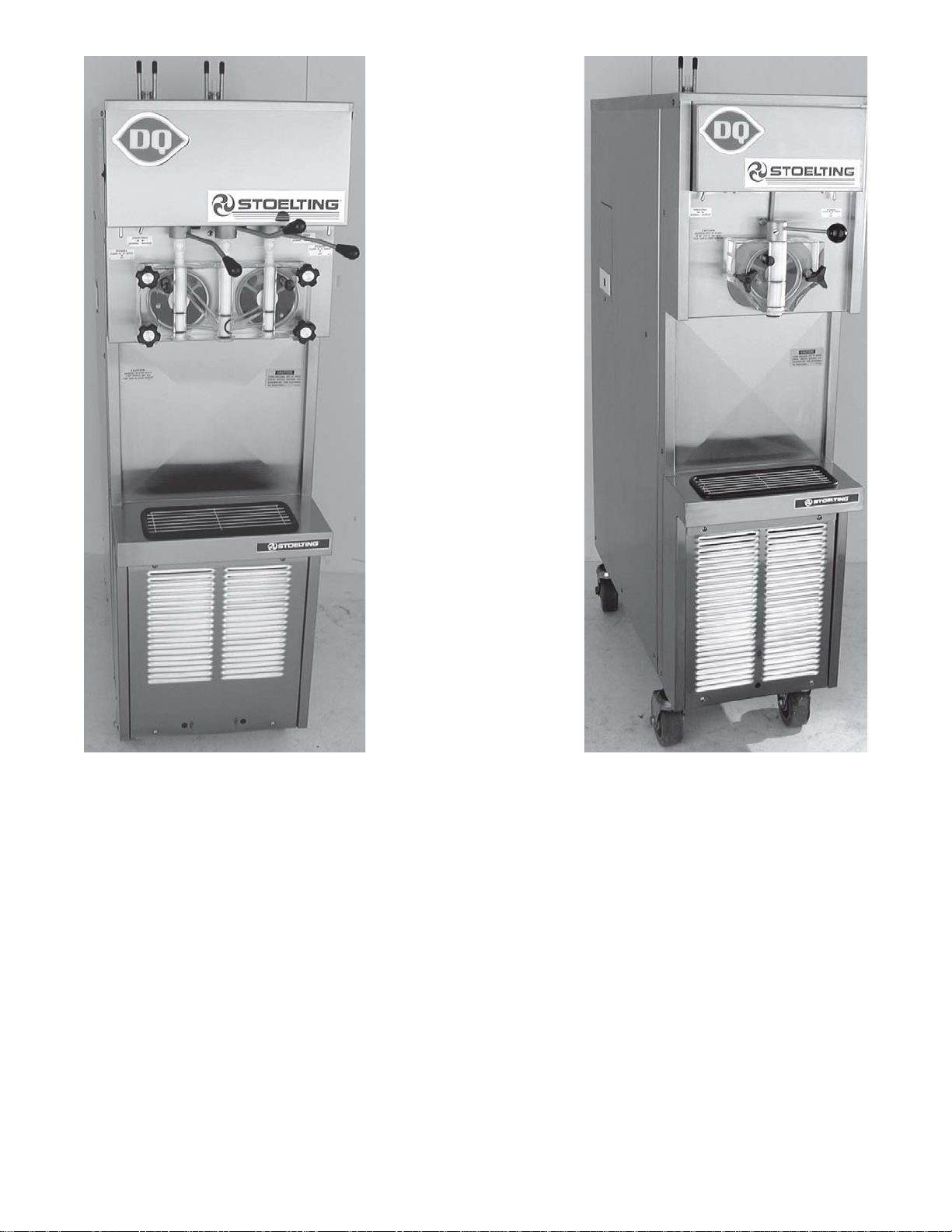
1.1 Description ......................................................................................................................1
1.2 Specifications ..................................................................................................................1
SECTION 2 -INSTALLATION
2.1Shipment andTransit........................................................................................................ 3
2.2Installation ........................................................................................................................3
2.3RemoteCondenser ..........................................................................................................5
2.4Mix PumpInstallationand Checkout(RemoteModels)......................................................7
SECTION 3 -OPERATINGINSTRUCTIONS
3.1SafetyInformation.............................................................................................................9
3.2SafetyPrecautions ...........................................................................................................10
3.3OperatingControls ...........................................................................................................11
3.4 Spigot Switch...................................................................................................................11
3.5DriveMotor Overload .......................................................................................................11
3.6 Main Drive (CLEAN-OFF-SERVE)...................................................................................11
3.7FreezingSwitch................................................................................................................11
3.8Door InterlockSwitch........................................................................................................11
3.9RemotePump Switch....................................................................................................... 11
3.10DispenseRateAdjuster ................................................................................................. 11
3.11HighPressure Cut Out....................................................................................................11
3.12SanitizingProcedures .................................................................................................... 11
3.13Initial Freeze DownandOperation..................................................................................12
3.14Removing Mix FromtheFreezer.....................................................................................13
3.15 Disassembly and Assembly of Front Door (Model 217 and 237R) ..................................14
3.16Disassemblyand Assembly of Auger .............................................................................16
3.17DisassemblyandAssembly of Mix Line Adaptor(RemoteModels) ................................17
3.18O-RingRemoval and Care .............................................................................................17
3.19Cleaningof Freezer and Freezer Parts...........................................................................17
3.20SanitizeFreezer Parts....................................................................................................18
SECTION 4-MAINTENANCEINSTRUCTIONS
4.1Freezer Adjustments ........................................................................................................19
4.2ProductTemperatureAdjustment......................................................................................19
4.3Drive BeltTensionAdjustment ..........................................................................................19
4.4CondenserCleaning (Air-Cooled Freezers) .....................................................................19
4.5Preventative Maintenance ................................................................................................20
4.6ExtendedStorage ............................................................................................................20
4.7Troubleshooting................................................................................................................20
SECTION 5 - HOW TO ORDER REPLACEMENT PARTS
5.1HowToOrder Replacement Parts ....................................................................................23
5.2PartsListand Reference Drawings ..................................................................................23

LIST OF ILLUSTRATIONS
Figure Title Page
1 CasterOptions ...................................................................................................... 3
2 WaterConnections................................................................................................ 4
3 ElectricalConnections........................................................................................... 4
4 AugerShaftRotation ............................................................................................. 5
5 RemoteCondenser ............................................................................................... 6
6 MixTransferLine&PumpInstallation .................................................................... 8
7 WarningLabelLocations....................................................................................... 10
8 OperatingControls ................................................................................................ 11
9 Air Bleed............................................................................................................... 12
10 PumpSwitch ......................................................................................................... 12
11 FrontDoorDisassembly........................................................................................ 14
12 SpinnerAssembly ................................................................................................. 15
13 AugerwithRubberRearSeal ................................................................................ 16
14 AugerDisassembly ............................................................................................... 16
15 Plastic Parts.......................................................................................................... 16
16 AugerAssembly .................................................................................................... 16
17 AugerFlightSpring ............................................................................................... 17
18 Mix Line Adapter ................................................................................................... 17
19 RemovingO-rings ................................................................................................. 17
20 Potentiometer........................................................................................................ 19
21 BeltAdjustment ..................................................................................................... 19

1
SECTION 1
DESCRIPTION AND SPECIFICATIONS
1.1DESCRIPTION
The Stoelting Challenger pressurized freezers are available in water cooled or air cooled versions (completely self-
contained or with remote condensers). Some models are available with built-in hoppers or remote mix pump feed.
Freezersare equipped with fully automatic controls to provide for consistenttemperature and uniformityof product.
Refer to Mix Pump Manual for complete information on the operation of the mix pump.
1.2SPECIFICATIONS
LEDOM NOITPIRCSED
712elytSpmuPreppoH-evreStfoS-lerraBelgniS
R712elytSpmuPetomeR-evreStfoS-lerraBelgniS
R522elytSp
muPetomeR-ekahS-rennipShtiwlerraBelgniS
R732elytSpmuPetomeR-evreStfoS-tsiwThtiwlerraBniwT
-fleS.rosserpm
ocekahsPH0.2dnaevrestfosPH5.2ahtiw,rotomevirdPH2aedulcnisledomevobaehT
.pmupxim912ledomgnitleotSahtiw,edisrepreppoh)retil7.42(nollag5.6evahsrezeerfdeniatnoc
LEDOM HTDIW
mc/ni
HTPED
mc/ni
THGIEH
mc/ni
.TWTEN
gk/bl
71283/515.99/52.93161/4.367.381/504
R71283/515.99/52.934.141/7.551.071/573
R52283/515.99/52.934.141/7.5
55.471/583
R7326.04/617.99/52.933.451/57.06452/065
:STNEMERIUQERLACIRTCELE
.elbaliavaeraztreh06,stlov032/802,esahp3rotlov032,esahP1-citsemoD
.stnemeriuqer
cificepsrofrezeerfehtforaerehttaetalpemanlacirtceleotrefeR-
.lenapredaehtnorfro,lenapedistfeldnihebdetacoltekcapnoitamrofninisimargaidgniriW-

2

3
SECTION 2
INSTALLATION
2.1 SHIPMENT AND TRANSIT
Thefreezerhasbeenassembled,operated,and inspected
atthefactory.Forshipment, the freezerisplaced onskids,
withsmall parts placed separatelyin boxes. Upon arrival
at the final destination, the freezer must be checked for
anydamagewhich mayhave occurred duringfinal transit.
With the sturdy packaging used, the equipment should
arrive in satisfactory condition. THE CARRIER IS
RESPONISIBLE FOR ALL DAMAGE IN TRANSIT,
WHETHER VISIBLE OR CONCELAED. Do not pay the
freight bill until you have checked the equipment. Have
the carrier note any visible damage on the freight bill. If
concealed damage and or shortage is found later advise
the carrier within ten days and request inspection. The
customermust place claim for damage and/or shortages
in shipment with the carrier. Stoelting, Inc. cannot make
any claims against the carrier.
2.2 INSTALLATION
Installationofthefreezerinvolvesmoving the freezerclose
toits permanentlocation, removingall protectivepackag-
ing, setting in place and cleaning.
A. Remove allprotective packaging. Removethe hold
downbolts fromthe woodenpallet, andwalk freezer
offthe pallet.
B. The freezer is shipped without legs.To install legs,
lift freezer and screw caster, extension, or leg into
the bottom of frame at each corner. Refer to caster
and leg options in Figure 1.
Figure 1. Caster Options
ForModelsDQ217,217R,225R,237R
WARNING
FREEZER MUST NOT BE ALLOWED TO TIP
MORETHAN10°.FAILURETOHEEDTHISWARN-
INGCOULD RESULT IN THE FREEZER FALLING
ON IT’S SIDE CAUSING SERIOUS DAMAGE OR
INJURY.
C. To level turn the top part of the caster or the bottom
partof the legin or out.Then level byplacing a level
on top of the freezer at each corner.
NOTE
Levelingis necessaryfor correct freezer drainage.
D. Forallfreezersallow aminimumof 6 inchesofspace
at the front and rear for air circulation. For efficient
operation,the room temperatureshould not bebe
low 60° F (16° C) or above 90° F (32° C).
E. For water cooled freezers, install a minimum of 1/2
inch pipe or 5/8 inch inside diameter copper water
lineto thefreezer.Thewater linemust beconnected
in a manner that will comply with local codes and
allowadequate roomfor servicing.
NOTE
All external plumbing is to be supplied by the customer.
Water lines connect to fittings at the rear of the freezer.
(SeeFig.2)Connecttheclean,potable, water inlettowater
source using flexible high water pressure line. Ordinary
gardenhoseis notrecommended. Connect thewater out-
let to flexible plastic tubing. The outlet can be secured to
floor drain, as the outlet is clean, warm water.
Option B - Casters & ExtensionsOption A - Casters

4
Figure 2
WaterConnections
Figure 3
ElectricalConnections
Water Out Water In
Access Holes

5
CAUTION
FLUSHALL WATER LINES BEFORE INSTALLA-
TION. IN NEW STORES WITH SEDIMENT IN
WATER, ADD SUITABLE FILTER OR STRAINER
TO WATER INLET. FAILURE TO FLUSH ALL
WATER LINES MAY RESULT IN EQUIPMENT
FAILUREAND EQUIPMENTDAMAGE.
F. Refer tonameplate at the sideof the freezer for
specificelectrical requirements. Connect electrical
power to the junction box at the rear of the freezer.
Bringwires into junction boxthrough access hole in
bottomrear of freezer.(Fig.3).
ATTENTION
The 24VAC pilot circuit is wired for a 240V supply.
If this freezer is installed in a location with a 208V
supply the transformer must be rewired. Remove
the left and right side panel to access.
CAUTION
ELECTRICALTECHNICIANSMUSTBECONTINU-
OUSLYALERT TO THE PRACTICE OF ALLNEC-
ESSARY SAFETY RULES AND PRECAUTIONS
WHEN SERVICING THIS EQUIPMENTAS VOLT-
AGESAREPRESENTWHICHCANCAUSESERI-
OUS OR FATAL INJURY.
ELECTRICAL WIRING MATERIALS, ARRANGE-
MENTANDGROUNDING MUST CONFORMWITH
NATIONALAND OTHERAPPLICABLEELECTRI-
CALCODES.
Figure 4
Auger Shaft Rotation
G. Check the auger shaft rotation by placing the MAIN
DRIVE switch in the CLEAN position. Auger shaft
rotationisclockwiseasviewedthroughtheclearplas-
tic front door. If the rotation is not clockwise, turn
mainelectrical power OFF.Then reverse anytwo
electricalpowerlinesin thejunctionbox(three phase
only).Recheck auger shaft rotation.(Fig.4)
NOTE
Threephase freezers in areasof unbalanced elec-
tricalloads require special attention whenconnect-
ing input electrical power. The unbalanced leg of
power(called wildor high)must beconnected to L2
in the junction box.
H. Remotefedfreezers requirean approved1/2 inch
(12.7mm) I.D. refrigeratedmix transfertube from
mix pump in walk in cooler to mix inlet at top of
freezer. Clamp both ends of tubing. Supportto
preventsagging and topromote totaldrainage when
not in use.
NOTE
Refer to the mix pump manual for complete infor-
mation on the operation of the mix pump.
2.3REMOTECONDENSER
The remote condenser can be installed either indoors or
outdoorswithout additional protectionrequired. Horizon-
tal installation requires the liquid line connection to be
made at the bottom of the coil. There should be no ob-
structions to the fan within five feet of the discharge.
NOTE
There must be an adequate supply of ambient air
below 120° F (49° C). Operating above this tem-
peraturewillresult inlossof capacity. Guardagainst
recirculationdue to dischargeinto anoverhang roof
or the side of the building.
A. Connect 230VAC, 60HZ, 1-PH to run the 1/6 HP,
2.8 AMP fan motor.
B. Connect refrigerantlines.Use3/8inch(9.52 cm)O.D.
copperline only.Trap hotgas line as shown(Fig.5).
Do not trap liquid line at all. If condenser is below
thefreezer, no trapsare required.(Fig.5)
NOTE
Maximum line length is 50 feet (15.24 meters).

6
Figure 5
RemoteCondenser

7
2.4 U3 MIX PUMP INSTALLATIONAND CHECKOUT
(REMOTE MODELS)
A. Follow the steps below to install the mix pump in an
uprightposition on the wall(allow clearance for a
mixcontainer under pump). See Fig.6.
1. Mountbylocating four (4) hole centers on cooler
wall using mounting bracket as template.
CAUTION
KNOW THE COOLER’S WALLDESIGN BEFORE
DRILLINGTOPREVENTPERSONAL INJURY OR
PROPERTYDAMAGE.
2. Drill four (4) 1/2" diameter holes into cooler wall
3/4"deep.
3. Insertwell-nutto flange and applysilicone seal-
antaround outside diameter of flangeand cooler
wall.
4. Repeatsteps2&3 for otherlocated hole centers.
5. Mount bracket to cooler wall with supplied wing
screws. Hand tighten until secure.
6. Mount pump to bracket with wing nuts.
B. Connect 1/2"(1.27cm) I.D.plastic foodgrade tubing
to the mix container. Secure with hose clamps. (5/
8" tubing is used with the 219 pump)
C. Connect 1/2" (1.27 cm) I.D. plastic food grade
tubing between the large port of air/mix tee and
refrigeratedmix transfer line.Secure withlarge hose
clampor equivalent.
D. Plug mix pump into a 115 volt grounded receptacle.
National sanitation foundation compliance require-
ments (Remote Pump)
In order to comply with the “National Sanitation Testing
Laboratory,Inc.” (NSF)code#6:
A. Thisunit(remotepump)mustbeinstalledwitha“NSF”
listedrefrigerated mix transferline. Themix transfer
line must be pitched to the cooler with no sags or
lowpoints, to allow complete drainage.(Fig.6).
B. The productatthemix pump andintransferline must
bemaintained below 41° F (5.0° C).

8
Figure 6
Mix Transfer Line
and Pump Installation

9
3.1 Safety Information
WARNING Readand understandtheentire manualbefore operatingor maintainingStoelting equipment.
ThisOwner’s Manualprovidesthe operatorwith informationfor thesafeoperation andmaintenance ofStoelting
equipment. As with any machine, there are hazards associated with their operation. For this reason safety is
emphasizedthroughout themanual.Tohighlight specificsafety information,the following safety definitions are
providedto assistthe reader.
The purpose of safety symbols is to attract your attention to possible dangers. The safety symbols, and their
explanations,deserve yourcareful attentionand understanding. The safety warningsdo notby themselveseliminate
anydanger.Theinstructions orwarnings theygive arenot substitutesfor properaccident preventionmeasures.
Safety Labels
Take notice ofall warninglabels on thefreezer (referto Figure 7).The labels havebeen putthere to helpyou
maintaina safeworking environment.The labelshave beendesigned towithstand washingand cleaning.All labels
must remain legible for the life of the freezer. Labels should be checked periodically to be sure they have not been
damagedor removedand thatthey canbe recognized as warning labels.
If you are in need of replacement labels, contact the authorized Stoelting distributor in your area.
DANGER
SAFETYALERT SYMBOL Indicatesdanger,warning orcaution.Attentionis
requiredin orderto avoidserious personalinjury.The messagethat followsthe
symbolcontains important information about safety.
DANGER indicatesanimminentlyhazardoussituation,which,ifnotavoided,will
resultin deathor seriousinjury andequipment/property damage.
WARNING indicates a potentially hazardous situation, which, if not avoided, may
resultin deathor seriousinjury andequipment/property damage.
CAUTION indicates a potentially hazardous situation, which, if not avoided, may
resultin minoror moderateinjury andequipment/property damage.
CAUTION indicates a potentially hazardous situation, which, if not avoided, may
resultin equipment/property damage.
NOTICE indicatesinformation or procedures thatrelate directly or indirectlyto
thesafety orpersonnel orequipment/property.
NOTICE
WARNING
CAUTION
CAUTION
SECTION 3
OPERATING INSTRUCTIONS

10
3.2SAFETY PRECAUTIONS
Donot attempt to operate the freezer untilthe safety pre-
cautionsandoperating instructions inthemanual areread
completelyand are thoroughlyunderstood.
SAFE OPERATION IS NO ACCIDENT; observe these
rules:
A. Know the freezer. Readandunderstandtheoperat-
ing instructions.
B. Notice all warning labels on the freezer.
C. Wear proper clothing. Avoidloose fittinggarments,
andremove watches, ringsor jewelry which could
cause a serious accident.
D. Maintain a clean work area. Avoid accidents by
cleaning the area and keeping it clean.
E. Stay alert at all times. Know which switch, push
button or control you are about to use and what
effect it is going to have.
F. Disconnect electrical power for maintenance.
Neverattempt torepair orperform maintenanceon
the freezer until the main electrical power has been
disconnected.
G. Do not operate under unsafe operating condi-
tions. Neveroperatethis freezer ifunusualor exces-
sivenoise or vibrationoccurs.
Figure 7
Warning Label Locations

11
3.3OPERATING CONTROLS
It is required that the operator know the function of each
controlorcomponentonthefreezerbeforeoperating.Refer
to Fig.8 for the location of the operating controls.
3.4 SPIGOT SWITCH
TheSPIGOT SWITCH will automaticallyactivate the au-
gerdrive andrefrigeration system whenthe spigotswitch
is opened to draw product.
3.5 DRIVE MOTOR OVERLOAD
The internal DRIVE MOTOR OVERLOAD will trip if the
drivemotor isoverloaded. Itwill reset after approximately
10-12minutes. Ifthe drivemotor continuesto trip, refer to
troubleshooting.
3.6 POWER SWITCH (Clean-Off-Serve)
ThePOWER switch isa three-positiontoggle switch used
to control the operation of the refrigeration system and
auger. When the switch is placed in the CLEAN position,
the refrigeration system will be off and the auger will ro-
tatefor cleaning.
Whenthe switch is placedin the OFF position, the refrig-
eration system and the auger are inoperative. When the
switch is placed in the SERVE position, the refrigeration
system and auger will be controlled automatically. The
switch must be placed in the SERVE position for normal
operation.
3.7 FREEZING SWITCH
TheFREEZINGswitchisatwo-positiontoggleswitchused
tocontrolthe operation oftheauger driveandrefrigeration
system. When the switch is placed in the MAXIMUM po-
sition,the freezer willcontinue to run for aminimum of 30
seconds after the spigot is closed. This time cycle pro-
videsmake-upcoolingperiodsofheavydispensing.Heavy
dispensingis drawing more than 18 ounces (.53 liters) in
oneminute.
When the switch is placed in the NORMAL position, the
freezer will continue to run for a minimum of 5 seconds
after the spigot is closed. This time cycle is to be used
during periods of normal dispensing. Normal dispensing
is drawing less than 18 ounce (.53 liters) in one minute.
NOTE
Do not leave the switch in the MAXIMUM position
duringslow or moderate dispensing as the product
temperaturewill become too cold.
3.8 DOOR INTERLOCK SWITCH
Whenthe door is securely fastened the freezer will oper-
ate normally. When the door is removed the drive and
compressorwill not run.
3.9 REMOTE PUMP SWITCH
TheOFF-ON REMOTEPUMP SWITCHis atwo-position
switch. When wired in series with the model 219 or U3
REMOTEPUMPOFF, pump operation can be controlled
fromthe frontof thefreezer.With the219 orU3 REMOTE
PUMP OFF-ON SWITCH in the ON position, place the
OFF-ON pump switch in the ON position and the pump
will start. Place the OFF-ON switch in the OFF position
and the pump will stop.
3.10DISPENSE RATEADJUSTER
Thedispenserateadjuster limitstheopeningof thespigot.
To adjust product dispense rate, turn the adjusting knob
clockwisefor slowerflow andcounter-clockwise for faster
flow.
3.11 HIGH PRESSURE CUT OUT
If the head pressure exceeds 405 PSIG the high head
pressure cut out will trip. The reset button can be ac-
cessedfrom the lower frontof the freezer.
3.12SANITIZING PROCEDURES
For sanitizing to be effective, it must be performed after
the mix pump and freezer parts have been cleaned, and
just prior to filling the hopper or storage container with
mix. Sanitizing the night before is not effective.
Whensanitizing thefreezer, refer to localsanitaryregula-
tions for applicable codes and recommended sanitizing
productsandprocedures.Thefrequencyofsanitizingmust
comply with local health regulations. Mix sanitizer ac-
cording to manufacturer’s instructions to provide a 100
parts per million strength solution. Mix sanitizer in quan-
tities of no less than 2 gallons (7.5 liters) of 120° F water.
Allow sanitizer to contact the surfaces to be sanitized for
5minutes. Anysanitizer must beused onlyin accordance
withthe manufacturer’s instructions.
Figure 8. Operating Controls
Pump Switch
Dispenser Rate Adjusters

12
NOTE
Stoelting has found that stera-sheen green label
sanitizerand cleaner does aneffective job of prop-
erly sanitizing and cleaning soft serve freezers. A
sampleis included witheach new freezer. Read di-
rectionsonpacket,formoreinformation.Otherprod-
ucts may be as effective.
CAUTION
PROLONGED CONTACT OF SANITIZER WITH
FREEZER MAY CAUSE CORROSION OF STAIN-
LESS STEEL PARTS.
ANY DISINFECTANT MUST BE USED ONLY IN
ACCORDANCE WITH THE MANUFACTURER’S
INSTRUCTIONS.INGENERAL, SANITIZING MAY
BECONDUCTED AS FOLLOWS:
A. Clean andlubricate parts.
B. Use a sanitizer mixed according to manufacturer’s
instructionstoprovidea100partsper million strength
solution.Mix sanitizer in quantitiesof no less than2
gallons (7.5 liters) of 120° F water.Allow the sani-
tizer to contact the surfaces to be sanitized for 5
minutes.
F. Check for leaks at three points when the freezer
barrel is first pressurized with sanitizing solution.
1. Check for leaks at the plastic front door O-rings
may not be sealing.
2. Open access door on the side panel. Make sure
the rear seal is not leaking.
3. Checkinthe hopper (hopper models) to see that
nobubbles are around the discharge end of the
mix transfer tube.
G. Usinga sanitized soft bristle brush or equivalent,
dipped in sanitizing solution, clean mix container
(remotemodels)orsidesof hopper,exteriorofpump,
andunderside of hoppercover (hoppermodels).
H. After five minutes, open spigot to expel sanitizing
solution.Drain all solution from freezer.
I. Close the spigot andplace themix pumpswitch and
the POWER switch in the OFF position.
Thefreezer is now sanitizedand ready for adding mix.
3.13 INITIAL FREEZE DOWNAND OPERATION
This section covers the recommended operating proce-
duresto be followedfor the safeoperation of thefreezer.
A. Sanitize justprior to useaccording to instructions in
section 3.11.
B. Prepare thedesired amountof mix andthen fillhop-
per(hopper models)or storage container (remote
models)with approximately three gallons (11 liters)
or more of mix.
NOTE
Hopper models must not be filled to more than 2"
(5 cm) from the top.
Figure 9. Air Bleed
Sanitizer must be used only in accordance with the
manufacturer’sinstructions. Pour into hopper (hop-
permodels) or storagecontainer (remote models).
C. Place the mix pump switch in the ON position and
openair bleedvalve on thefront doorby pushing
valvein andholding. (SeeFig.9)
D. Letsanitizingsolutionfillthefreezerbarreltoair bleed
valve, then close the valve by pulling out to lock in
place.
E. Place the MAIN DRIVE switch in the CLEAN
position. Figure 10. Pump Switch
Air
Bleed
Pump Switch
This manual suits for next models
4
Table of contents
Other Stoelting Dispenser manuals

Stoelting
Stoelting C111 User manual

Stoelting
Stoelting Endura 131G User manual

Stoelting
Stoelting Optima SO328 User manual

Stoelting
Stoelting F131-YG2 User manual

Stoelting
Stoelting CF101 User manual

Stoelting
Stoelting CW5-37A Release Note

Stoelting
Stoelting O231-I2F User manual

Stoelting
Stoelting E131I2 User manual

Stoelting
Stoelting O111-I2F User manual

Stoelting
Stoelting CW5-37B Release Note