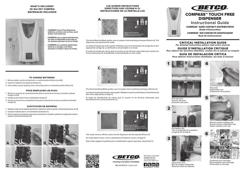
ADAST V-line 899 LPG HYBRID Series User manual

Adast Systems, a.s., 679 04 Adamov No. 496, Czech Republic
www.adastsystems.cz
MKT-001-01-2011/MSS/A
XI/2017
USER´S MANUAL
Instructions for Operation, Maintenance
and Installation
Combined dispenser
for dispensing classic and alternative
liquid fuels and liquefied
propane-butane
V-line 899x.xxx/LPG HYBRID


USER’S MANUAL V-line 899x.xxx/LPG HYBRID
I
CONTENT
1. IMPORTANT NOTICE ................................................................................................... 1
2. USE ........................................................................................................................ 2
3. INSTRUCTIONS FOR THE SAFETY OF WORK ...................................................................... 2
3.1. Safety of the equipment design..............................................................................2
3.2. Operation safety ................................................................................................3
3.3. Ecological safety ................................................................................................3
3.3.1. Petrol delivery module............................................................................3
3.3.2. LPG delivery module...............................................................................5
3.4. Hygiena ...........................................................................................................5
3.5. The first aid principles in case of LPG injury ..............................................................5
4. DESCRIPTION ............................................................................................................ 5
4.1. Skeleton ..........................................................................................................7
4.1.1. Case of the electronic counter ..................................................................7
4.1.2. Case of the electronic counter –design 2017 (see fig.) .....................................8
4.2. The integrated hydraulic unit for petrol or diesel ........................................................8
4.3.1. The hydraulic system of the fuel dispenser V-line 899x.xxx/LPG - piston volumetric
flow meter ADAST M 406.xxxx: ................................................................ 12
4.3.2. The hydraulic system of the fuel dispenser V-line 899x.xxx/S/LPG HYBRID with
a mass flow meter ............................................................................... 13
4.4. Elektronics ..................................................................................................... 14
4.4.1. Communication to the control system ....................................................... 15
4.4.2. Elektronics fuel dispenser V-line 899x.xxx/LPG/M HYBRID............................... 15
4.5. Vapour recovery system ..................................................................................... 15
4.5.1. Description of vapour recovery system....................................................... 16
4.5.2. System VRC-M..................................................................................... 16
4.5.3. System VRC-E ..................................................................................... 18
4.5.4. System VRC-M with VRMS ....................................................................... 19
4.5.5. System VRC-E with VRMS........................................................................ 22
4.5.6. Function of system VRC with VRMS ........................................................... 25
4.5.7. Indication of system status VRMS............................................................. 26
4.6. Signalling of dispenser conditions (SO) ................................................................... 28
4.7. SOPA design.................................................................................................... 29
4.8. Design with heating of the electronic case .............................................................. 29
5. TECHNICAL DATA......................................................................................................29
6. IDENTIFICATION .......................................................................................................31
7. DISPENSER OPERATION –PETROL AND DIESEL ..................................................................32
7.1. Attendance..................................................................................................... 32
7.1.1. Dispensing with preselection................................................................... 33

USER’S MANUAL V-line 899x.xxx/LPG HYBRID
II
7.1.2. Description of the preselection function ................................................... 33
8. DISPENSER OPERATION –LPG....................................................................................... 33
8.1. Attendance .................................................................................................... 33
8.2. Dispensing with service...................................................................................... 34
8.3. Self dispensing ................................................................................................ 34
8.4. Dispensing with preselection ............................................................................... 35
8.5. Description of the preselection function ................................................................. 35
9. FUNCTIONS OF KL-MANINF MANAGER AND KL-SERINF SERVICE KEYBOARDS ............................ 36
9.1. Manual setting of unit prices ............................................................................... 36
9.2. Setting of unit price values from the control system in AUTO mode................................ 37
9.3. Display of electronic totalizers ............................................................................ 37
9.4. Check of vapour recovery system function .............................................................. 38
10. MAINTENANCE OF A DISPENSER AND ITS INDIVIDUAL OPERATING UNITS –MODULE FOR DISPENSING
PETROL AND DIESEL .................................................................................................. 38
10.1. Pumping monoblock.......................................................................................... 38
10.1.1. Changing the filter element.................................................................... 39
10.2. Piston flowmeter ............................................................................................. 39
10.3. Electromagnetic two-stage valve .......................................................................... 39
10.4. Sight glass of the dispenser ................................................................................. 39
10.5. Dispensing hose ............................................................................................... 39
10.6. Dispensing nozzle ............................................................................................. 40
10.7. V-belt of the pump ........................................................................................... 40
10.8. Dismantling of covers ........................................................................................ 40
10.8.1. Covering of MONO, DUO hydraulic modules. ................................................ 40
10.8.2. Covering of DUPLEX hydraulic module. ...................................................... 40
10.8.3. Covering of counter case ....................................................................... 40
10.8.4. Dismounting of the metering unit............................................................. 40
10.8.5. Dismounting of the electromagnetic valve .................................................. 41
10.8.6. Dismantling of the vacuum pump set......................................................... 41
10.8.7. Dismantling of distribution piping............................................................. 41
10.9. Electronic counter............................................................................................ 41
11. DISASSEMBLY AND DISPOSAL ....................................................................................... 41
12. SUMMARY OF BASIC PRINCIPLES FOR DISPENSER MAINTENANCE ........................................... 41
13. MAINTENANCE OF THE DISPENSER AND ITS INDIVIDUAL OPERATING UNITS –MODULE FOR
DISPENSING LPG ....................................................................................................... 42
13.1. LPG piston flow meter ....................................................................................... 42
13.2. Differential valve ............................................................................................. 42
13.3. Separator....................................................................................................... 42
13.4. Electromagnetic two-stage valve .......................................................................... 43
13.5. Breakage coupling ............................................................................................ 43

USER’S MANUAL V-line 899x.xxx/LPG HYBRID
III
13.6. Rupture coupling.............................................................................................. 43
13.7. LPG sight-glass ................................................................................................ 43
13.8. Dispensing hose ............................................................................................... 43
13.9. LPG dispensing nozzle ....................................................................................... 44
13.10. Dismantling of covers ........................................................................................ 44
13.10.1. Covering of duplex hydraulic modules ....................................................... 44
13.10.2. Covering of counter case ....................................................................... 44
13.10.3. Dismantling of the metering unit.............................................................. 44
13.10.4. Dismantling of the electromagnetic valve ................................................... 44
13.11. Maintenance instructions for dispenser body parts..................................................... 45
13.12. Electronic counter ............................................................................................ 45
14. DISASSEMBLY AND DISPOSAL .......................................................................................46
15. SUMMARY OF BASIC PRINCIPLES FOR DISPENSER MAINTENANCE ...........................................46
15.1. Module for dispensing petrol and diesel .................................................................. 46
15.2. Module for dispensing LPG .................................................................................. 46
15.2.1. Principles of service interventions for LPG dispenser ..................................... 46
15.2.2. Summary of principles for inspection of LPG Dispenser................................... 47
16. TRANSPORT ............................................................................................................47
17. DISPENSER INSTALLATION...........................................................................................47
17.1. Hydraulic part for dispensing petrol and diesel ......................................................... 48
17.1.1. Installation on the filling station with underground tanks................................ 48
17.1.2. Installation at the filling station with overground (aboveground) tanks ............... 49
17.1.3. Mounting of spring of the spring hinge ....................................................... 51
17.2. Hydraulic parts for dispensing LPG ........................................................................ 52
17.3. Hydraulic section ............................................................................................. 52
17.4. Wiring ........................................................................................................... 52
18. PUTTING OF THE DISPENSER INTO OPERATION.................................................................53
18.1. Module for dispensing petrol and diesel .................................................................. 53
18.2. Putting the dispenser and electronic counter into operation......................................... 53
18.3. Shutdown of the dispenser and electronic counter..................................................... 53
18.4. Restart of the dispenser and electronic counter after power failure and voltage drop ......... 53
18.5. Module for dispensing LPG .................................................................................. 54
18.6. Putting of the dispenser and electronic counter into operation ..................................... 54
18.7. Shutdown of the dispenser and electronic counter..................................................... 54
18.8. Restart of the dispenser and electronic counter after power failure and voltage drop ......... 54
19. PACKING AND STORAGE..............................................................................................54
19.1. Packing ......................................................................................................... 54
19.2. Storage ......................................................................................................... 54
20. GUARANTEE AND CLAIMING.........................................................................................55

USER’S MANUAL V-line 899x.xxx/LPG HYBRID
IV
21. SPARE PARTS CATALOGUE .......................................................................................... 56
22. ACCESSORIES........................................................................................................... 56
23. DOCUMENTATION DELIVERED ...................................................................................... 56
24. ENCLOSURES ........................................................................................................... 56

USER’S MANUAL V-line 899x.xxx/LPG HYBRID
1
1. IMPORTANT NOTICE
The instructions for attendance, maintenance and installation serve the user to gain information on the
design, correct attendance, maintenance and safe installation.
The information included in the present instructions are mandatory and the manufacturer does not accept
any responsibility for any damage due to their non-observance.
The dispenser is complicated equipment providing many important functions.
Prior to putting into operation tanks and the piping system shall be cleaned and fuel purity shall be
checked. Also el. power distribution and correct wiring shall be inspected to prevent injury by el.
current and to provide explosion proofness –fuels are flammable liquids of the 1st and 2nd danger
class!
The manufacturer tests each dispenser considering the function, safety and metrology. Each delivery shall
include the instructions for attendance, maintenance and installation, EC declaration of conformity and a
service book identifying dispenser components. The dispenser, produced with high precision and care,
secures reliable and safe operation. Principal safety regulations protecting the user against injury shall be
kept during operation and maintenance and the dispenser shall be prevented from damage. No
modifications of the dispenser equipment are allowed without producer’s written approval.
The dispenser has been designed for outdoor installation –class according to OIML D11 –C (outdoor -
stationary).
Important instructions for installation and operation:
a) Only qualified and trained staff of a service company can perform service and installation.
Service procedures shall be performed in compliance with the operation regulations of the
filling station. The manufacturer is not responsible for damages due to the incompetence of
the staff.
b) Prior to proceed to the dispenser handling, study these Operating User’s manual and other
manufacturer’s documents belonging to the dispenser accessories carefully.
c) Check the dispenser delivery for completeness and in the case of any discrepancy or damage,
inform supplier or the manufacturer without delay.
d) Ensure the proper storage of the dispenser in a dry and protected room for the pre-installing
period.
e) Prior to installation, check the dispenser for the completeness of the filling station technology
against the valid project, and revise the connecting dimensions of the base frame including the
outlet of the piping system.
f) Rinse the technological equipment (piping systems) through the filtering device and continue
rinsing until the filtering device remains free of impurities.
g) With respect to operating safety it is necessary at dispenser installation situate with
connection of dispensing hose in the direction of exit from the filling station.
h) The module requires the connection of the vapour return piping of min. DIN 16 –we
recommend DN 25.
i) The dispenser requires the connection to the return piping of a DN 16 (1/2“) inner diameter.
j) Connect the dispenser electrical equipment and revise it.
k) Carry out the pressure test of the dispenser including its piping systems with a 2,5 MPa pressure
and revise it.
l) For putting the dispenser into operation, proceed in accordance with the point 17.
m) Carry out the test for proper function and entrust the metrological verification to a metrological
authority representative.
n) On meeting all of these requirements and after the approval by the representatives of the
metrological authority, the standard operation may start.
ATTENTION!
The dispenser shall not be installed in an explosion danger zone 0, 1, 2 in compliance with zones
specified in the EN 60079-10-1!

USER’S MANUAL V-line 899x.xxx/LPG HYBRID
2
o) The servicing interventions should be entrusted to the properly trained personnel of the service
firm only.
p) When fuels are pumped, basic hygienical precautions shall be adhered. The owner shall
enable the customer to use protective gloves.
SAVE FOR FUTHER USE!
2. USE
Combined fuel dispensers type series V-line 899x.xxx/LPG HYBRID with electronic counter used for
the dispensing of liquid petroleum products - automotive petrol, diesel, kerosene, etc., of
alternative liquid fuels (biofuels) - biodiesel (B 10 - B 100) - a mixture of diesel fuel with FAME
(Fatty Acid Methyl Ester) and a mixture of automotive petrol with bioethanol (E10 - E 85) (flammable
liquids I. to IV. hazard class and group explosivity IIA) with dynamic viscosity up to 20 mPa.s and
with flow rate optional 40, 60, 70, 80 m3.min-1 and for the dispensing of liquefied propane-butane
(LPG) with flow rate optional 30, 40 dm3.min-1.
The LPG dispensing module is intended for the supply of LPG - a mixture of propane-butane (motor
fuel according to EN 589+A1) and pure propane (motor fuel - gas according to EN 589+A1) in metal
pressure vessels installed in motor vehicles.
Hybrid V-line 899x.xxx/LPG HYBRID dispensers are designed for the delivery of classic and alternative
liquid fuels and LPG at fuel filling stations.
They allow one-sided or double-sided simultaneous dispensing of petrol and LPG into one vehicle at the
same dispensing point.
The dispensers are equipment with special requirements concerning safety, metrology and ecology.
The dispensers are equipped to exhaust vapours; thus ecological operation of filling stations is provided,
i.e. the prevention of harmful petrol vapours leakage into atmosphere.
A gas leakage detector connected to the monitoring unit in the filling station booth can be installed in the
LPG dispensing module for safe and ecological operation of the filling station.
The instructions for attendance, maintenance and installation serve the user to gain information on the
design, correct attendance, maintenance and safe installation.
3. INSTRUCTIONS FOR THE SAFETY OF WORK
ATTENTION!
Any handling open flame is prohibited during fuel filling and smoking is prohibited even in vehicles
interior. Also filling vehicle tanks with running motor and any other activities possibly initiating
explosion are prohibited!
Smoking and open fire manipulation is prohibited within a radius of 10 meters of LPG filling. This
prohibition shall be visibly located. An explicit warning for engine out and max. filling of 80 % is on
the LPG dispensing module. Vehicles must be prevented from spontaneous movement.
The instructions for attendance, maintenance and installation serve the user to gain information on the
design, correct attendance, maintenance and safe installation.
3.1. Safety of the equipment design
The manufacturer guarantees safety of the equipment design.
The dispenser design complies with the EN 13617-1+A1 and EN 14678-1+A1 requirements and it is
homologated for the operation in environment specified by II2G IIAT3 symbols shown on the
dispenser plate.
Considering operation safety in environs with explosion danger the dispensers have been EC –type
examination (certification) according to the Annex III of the Directive 94/9/EC –ATEX by an
authorised body FTZÚ, Pikartská 7, 716 07 Ostrava –Radvanice –Notified body no. 1026.
EC - Type Examination Certificate: No. FTZÚ 11 ATEX 0204X

USER’S MANUAL V-line 899x.xxx/LPG HYBRID
3
Regular inspection of production quality assurance according to Annexes IV and VII of the Directive
94/9/EC executes FTZÚ, s.p., Ostrava –Radvanice, Notified body no. 1026.
Notification of quality assurance: No. FTZÚ 02 ATEX Q 020.
Considering legal metrology the dispensers have been EC –type examination (certification) according
to the annex B of the Directive 2004/22/EC –MID by an authorised body Český metrologický institut,
Okružní 31, 638 00 Brno – Notified body no. 1383.
EC - Type Examination Certificate: No. TCM 141/07 –4505 and TCM 141/07 –4506
The producer performed a conformity examination for the fuel dispenser with the type described in
EC –Type Examination Certificate No. TCM 141/07 –4505 and TCM 141/07 –4506 and technical
requirements according to the Directive of European Parliament and the Council 2004/22/EU.
The producer is competent for “The Declaration of Conformity” with the type based on production
quality assurance of measuring units according to the Directive Supplement D of European Parliament
and the Council 2004/22/EU.
Certificate of the Quality Management System for production, check-out and testing:
no. 0119-SJ-C007-07.
3.2. Operation safety
The owner is responsible for the filling station operation and is obliged to follow the course of fuel
pumping. In case a customer uses the dispenser incorrectly, the owner shall instruct him about proper use.
The owner shall also identify the hazard zone of the filling station by warning symbols (smoking
prohibited, open flame prohibited, direction of arrival to dispensers, etc.).
Operation regulations of the filling station shall be accessible for the customer, which enables him to get
information on principal obligations.
Operator’s obligation:
–Keep the operated equipment in safety and proper conditions.
–Follow the filling station operating regulations and gas equipment operating instructions.
–Without delay report any defect, failure or irregularity arisen in the course of the gas equipment
operation to the keeper and, in case of a danger in delay, put the equipment out of operation
immediately.
–Keep the gas equipment clean and in order permanently and take care with avoiding the presence of
strangers close to the equipment.
–Without delay report the circumstances that make him more difficult the equipment operation
(sudden indisposition, for instance)
–Record the data on the beginning and the end of the work shift and the results of revisions made by
the operators and the extent of maintenance, repairs, checks and revisions performed.
–The dispenser and storage tank operators are not supposed to make any repairs of mechanical section,
and to alter the setting of any safety fittings.
Performance of service work is a special case. Servicemen are not allowed to break operation safety
during repairs and other activities. When dispenser covers are removed, they shall be very careful to
protect both them and customers against injury.
El. current supply shall be disconnected when handling el. components. Only approved components
shall be used to replace any parts.
All parts subject to approval shall be always in conditions required by the technical documentation
(leakproofness, earthing, electrostatic belts, electrostatically conductive filling hoses, etc.).
3.3. Ecological safety
3.3.1. Petrol delivery module
In accordance with the „DIRECTIVE 2009/126/EC OF THE EUROPEAN PARLIAMENT AND OF THE COUNCIL
of 21 October 2009 on Stage II petrol vapour recovery during refuelling of motor vehicles at service
stations“must be filling station for dispensing petrol equipped according to the national legislative
regulations of the country of destination (installation and operation of fuel dispensers) Decree recovery
system (reverse drain stage II petrol vapor - Equipment recuperate (consultation draft) petrol vapor

USER’S MANUAL V-line 899x.xxx/LPG HYBRID
4
displaced from the fuel tank of a motor vehicle during refueling and carrying petrol vapors to the storage
tank at the service station.
IMPORTANT NOTE!:
Terms of service stations and control petrol vapor recovery system stage II is drived by the
"Directive 2009/126/EC of the European Parliament and Council" and the relevant national legal
regulations in force in the countries of destination (installation and operation of fuel dispensers).
Fuel dispensers ADAST V-line 899x.xxx for dispensing of petrol are equipped with an efficient
recovery system (reverse exhaust vapor) that meets the requirements of the "Directive
2009/126/EC of the European Parliament and Council”:Volumetric efficiency of vapor recovery
shall be between 95-105% - the rate of the volume of recovered vapor at atmospheric pressure to
total dispensed petrol into the fuel tank of a motor vehicle is equal to or greater than 0,95 but less
than or equal to 1,05.
Check of petrol vapor control system –by the Directive 2009/126/EC
Check of petrol vapor recovery system Stage II at the dispenser shall be in accordance with
Directive 2009/126/ES under the relevant national legislation and regulations applicable in the
countries of destination (installation and operation of fuel dispensers).
Regular checks under Directive 2009/126/EC
1. Checking the operating efficiency of petrol vapor recovery system Stage II must be
performed at least once per year. Checks whether the ratio is the ratio of the volume of
paid vapor at atmospheric pressure to the total volume of petrol fished into the fuel tank of
a motor vehicle is equal to or greater than 0,95 but less than or equal to 1,05.
2. If the dispensers installed automatic monitoring system, the efficacy of petrol vapor
recovery stage II tested at least once every three years. Any such automatic monitoring
system shall automatically detect faults in the proper function of petrol vapor recovery
system Stage II and in the automatic monitoring system, indicate faults to the service
station and automatically stop the flow of petrol from the faulty dispenser if the fault is not
rectified within seven days.
IMPORTANT NOTE!:
All fuel dispensers used for dispensing petrol must be equipped with clearly labeled, indicating the
need for customers to fully insert the nozzle into the filler neck of the vehicle tank.
Check of petrol vapor recovery system Stage II at fuel dispensers
ADAST POPULAR V-line 899x.xxx.
To check the operating efficiency of petrol vapor recovery system Stage II are two procedures:
1. Procedure for dispensers where the pump driven by an electric pump without electronic
control system vapor recovery:
The test is performed for pumping petrol into a suitable volumetric container at 50% and 100%
of the nominal flow of petrol. Measuring the effectiveness of this system is carried out solely
for the purpose meter designated as a special meter Bürkert G4-RF1 connected to the suction
nozzle attachment with a universal connector UMAX 2 companies ELAFLEX).
2. Procedure for dispensers with electronically controlled petrol vapor recovery system Stage
II, which allows to perform the test without using petrol:
The test is carried out so-called "dry way" apparatus approved for this purpose - eg special
meter Bürkert G4-RF1 connected to the suction nozzle attachment with a universal connector
UMAX 2 companies ELAFLEX). Gas meter Bürkert G4-RF1 is via pulse output is connected
through a special cable to enter the electronic counter. Linking meter counter and must be
done at a gas station through the reduction of RP/M/EX, which contains zener barrier for
intrinsic safety.

USER’S MANUAL V-line 899x.xxx/LPG HYBRID
5
3.3.2. LPG delivery module
A gas leakage detector can be located in the dispenser module area (optional - not a part of the standard
delivery) which is connected to the evaluating unit signalling leakage in case of a small leakage (low
concentration) and putting the filling system out of operation in case of higher concentration. In case of a
small leakage the operators check the system and if a defect in not found out, escaped gas is exhausted
and the system put in operation. In case of higher concentration the attendant puts the dispenser out of
operation and reports the defect to the authorised service.
3.4. Hygiena
The dispensers are hygienically harmless for customers and the owner. But protective gloves are advised
to be used during maintenance or filling fuel. In case skin comes to contact with fuel or impurities, wash
the spot with water and soap as soon as possible. When eyes come to contact, medical treatment is
necessary. Do not inhale harmful vapours when filling fuel.
For carrying out the routine maintenance and dispensing the liquefied propane-butane (LPG), it suits to
protect the hands with gloves.
3.5. The first aid principles in case of LPG injury
It is necessary to prevent inhalation of propane-butane vapour during pumping - there is a
danger of asphyxia. The injured person shall be taken out from the hazardous area to the fresh
air. Take care of your own safety. Be also aware of fire and explosion risk. Put the injured
person comfortably, release their clothes and leave them in absolute rest (they are not supposed
either walk or speak). Call a physician or take the injured person to a hospital. In case of
dyspnoea or stoppage of breathing give them oxygen or apply artificial respiration.
In case of LPG contamination of eyes pour a small quantity of water on them, carefully open eye-
lids and rinse the eyes with plenty of running water (for about 15 minutes) then look for medical
care - there is a danger of cornea injury.
In case skin gets in contact with propane-butane, rinse the skin with plenty of water, take off the
clothes and shoes that have been contaminated (take care of fire and explosion risk) and rinse the
attacked skin with running water (for about 15 minutes). Do not chafe chilblained skin but cover it
with a sterile bandage.
In case of a burn it is advised to cool the injury with cold water from water main. Do not apply
anything on the injury and visit a physician. Apply only sterile bandage in emergency or in case of
extensive burns wrap the injured person into clean bed sheet - do not take off clothes. In case
the clothes are burning do not run (the flames can blow up), extinguish it by water, stifle the
flames with a blanket or jacket - by rolling on the ground. In case of being in the centre of fire,
lie down immediately. Flames and gas attacking the face can result in lethal burning of breathing
organs.
4. DESCRIPTION
The combined fuel dispenser allows the simultaneous dispensing of two types of liquid fuel - petrol or
diesel fuel and liquefied propane-butane (LPG) into a motor vehicle at the same dispensing point.
The V-line 899x.xxx/S/LPG HYBRID dispensing racks are designed for the suction pump system with its
own pumping aggregate of the classic liquid fuel (petrol or diesel) in the dispenser.
The V-line 899x.xxx/P/LPG HYBRID dispensing racks are designed for a central push system where the
flow of the submersible pump is located in the storage tank of the pumping station - for classic liquid fuel
(petrol or diesel) and LPG.
The dispensers have been designed for the installation at road filling stations and a fleet of vehicles, etc.
By means of a communication line the dispensers are connected to the control system of self-service
operation or serviced.
Fuel dispensers are designed as self-contained sectional contruction. Two-space body is designed in the
with two columns for two products.
Construction of V-line 899x.xxx/LPG HYBRID fuel dispensers consist from following basic modules:

USER’S MANUAL V-line 899x.xxx/LPG HYBRID
6
Position
number
Name of the part of dispenser V-line 899x.xxx/x/LPG HYBRID
1
Skeleton
2
Hydraulic unit for the delivery of classic liquid fuel (petrol or diesel)
3
Hydraulic unit LPG
4
Vapour recovery system
5
Electronic counter with wiring
6
Dispensing hose ADAST, ELAFLEX, GOODYEAR, ТRELLEBORG
7
Dispensing nozzle ELAFLEX, OPW , ABR, RAKORD
8
Safety Swivel Break ELAFLEX, OPW
9
Sight glass ADAST, ELAFLEX
10
Reducer
11
Transit socket
12
Safety socket
13
Spring
14
Spring
15
Dispensing hose LPG ADAST, ELAFLEX, SEMPERIT
16
Dispensing nozzle LPG OPW-BREVETTI NETTUNO, HEFA, STÄUBLI, ELAFLEX, LPG GROUP
17
Breakage coupling ADAST or rupture coupling ELAFLEX, OPW, LPG GROUP
18
Immediate piece
19
Immediate piece

USER’S MANUAL V-line 899x.xxx/LPG HYBRID
7
4.1. Skeleton
Skeleton –a self-supporting structure consisting of parts with high anticorrosive resistance. The base of
the dispenser is made of steel sheet, zinc-coated and varnished. Internal parts of the skeleton are made
of galvanised sheet. Parts of the body with the exception of the door of the hydraulic module and the
electronic counter case are made of stainless brushed sheet as a standard.
High resistance acrylurethane enamel is applied on the hydraulic module door and the electronic counter
case. The colour shade of the door including the logo can be optional.
Both doors are lockable; being unlocked, swing out and with earth wire disconnected they can be removed
and thus the hydraulic part is accessible. Connect the earth wires when the door is fitted back. A junction
box is built-in into the supporting column and is accessible after dismounting the side cover of the
column.
4.1.1. Case of the electronic counter
A case of the electronic counter or ADAMAT electronics is bolted to the column. The counter case space is
closed with lockable covers. The covers are provided with transparent glass. Indicators with integrated
large-area display of dispensed volume, total price, price for one unit and unresetable electromechanical
total counters (totalizers) are connected from the case interior to the covers. The set of these elements
represents all necessary information for the customer.
The covers of the case are hung up on hinges enabling tilting upwards after unlocking and thereby easy
access in the case interior. The user’s local preselection keyboard (if required) is located on the case
cover as well - an independent keyboard for each dispensing point.
Dispensing nozzle for
petrol or diesel
Dispensing nozzle
for LPG

USER’S MANUAL V-line 899x.xxx/LPG HYBRID
8
4.1.2. Case of the electronic counter –design 2017 (see fig.)
A case (1) of the electronic counter or ADAMAT
electronics is bolted to the hose module column.
The counter case space is closed with lockable
covers (2). The covers are provided with
transparent glass.
On the inside cover of the case is mounted under
glass large-area display (3) issued volume and
total price, which displays all necessary
information for the customer.
Above the display is placed IR sensor (5) for
controlling and adjusting the dispenser
calculator manager or servicing keyboard.
On the outer side of the case cover is placed
(optional) keyboard local user preferences (4) -
an independent keyboard for each dispensing
point.
On request they can be built in a case unresetable electromechanical total counters –totalizers (6), which
are accessed by opening the cover.
ATTENTION!
Before opening the covers, it is always necessary to disconnect power to the dispenser and
perform a reliable hedge against its re-connection.
The dispensing nozzles are seated in covers in the „V― form pressed shape of the column. When the
dispenser is out of operation the dispensing nozzles in covers can be locked.
4.2. The integrated hydraulic unit for petrol or diesel
Position
number
Components integrated hydraulic unit for petrol or diesel
1
Pumping monoblock ADAST P64x.50, P64x.100
2
Filter
3
Four-piston all-aluminium meter and an integrated magnetic pulse transmitter ADAST M
403.25P, M 403.32P, M 403.25EP, M 403.32EP, 403.25P/1, M 403.32P/1, M 403.25EP/1, M
403.32EP/1
4
Magnetic pulse transmitter ADAST 40 or ELTOMATIC ME 01-05 nebo ME 01-05-05,
METRA MTX 075
5
Electromagnetic valve
6
Connection piece 250-CP
7
Vacuum pump
8
Tree-weldment - joining piece
9
Monoblock bracket
10
Vacuum pump bracket
11
V-belt ELECTROOIL of Pumping monoblock
12
V-belt ELECTROOIL of Vacuum pump
13
Electric motor

USER’S MANUAL V-line 899x.xxx/LPG HYBRID
9
The integrated hydraulic unit consists of a pumping monoblok (pos. 1) with an integrated large-surface
filter (pos. 2), a meter (pos. 3) with integrated magnetic pulse transmitter (pos. 4) connected with the
pumping monoblok (pos. 1) through a special joining piece (pos. 8) and a driving el. motor (pos. 13) of
the pump.
Pumping monoblock type series P 64x.xxx/x (pos. 1) –is an independent unit for one kind of the
pumped fuel. An integrated compact structure contains an efficient filter (pos. 2), sliding vane pump,
control and non-return valves, safety relief valve with continual control of the operating pressure, cyclone
(centrifugal) gas separator and a venting chamber with a float valve. Progressive design provides 100 %
separation of gaseous components and automatic blocking of filling when excessive amount is identified in
the product pumped.
The large-surface filter with an integrated non-return valve and standard filtration efficiency 30 µm
for petrol and optional 30 µm or 60 µm for Diesel oil (winter operation in extreme low temperatures).
The pumped liquid passes through the filter (pos. 2) and the non-return valve to the pump and the
separator where gases and vapours are separated and pass to the float chamber. Condensed liquid is
discharged to the suction part of the pump and gases are exhausted to the vented part of the dispenser
base. The liquid is discharged from the non-return valve to the meter (pos. 3), then through an
electromagnetic valve (pos. 5) into the dispensing hose with a dispensing nozzle at its end. The dispensing
nozzle lever controls the rate flow. A tube sight glass can be installed between the dispensing hose and
the nozzle for visual checking.
A three-phase asynchronous motor (pos. 13) drives the pump by means of an antistatic V-belt (pos. 11).
Special modifications of the pumping monoblok of P 64x.xxx/x/BIO series is intended to measure
the volume of biofuel - a mixture of automotive petrol with bioethanol (E10 - E 85).
It has a special surface protection, which ensures their high resistance against aggressive biofuels.
Dispensers V - line 899x.xxx/P series (pressure design) differ from suction dispensers because they are
not equipped with the pumping monoblock. A safety breaking valve shall be fitted in the connection. The
valve prevents fuel leakage in case of the dispenser damage. This valve is not a part of the dispenser, as

USER’S MANUAL V-line 899x.xxx/LPG HYBRID
10
well as the pump, which is located in the underground tank. The pressure dispensers are equipped with an
inlet spherical valve for closing the liquid input in case of repairs.
The pumped liquid is supplied from the central submerged pump located directly in the fuel storage tank
through the safety breaking valve, spherical check valve and the filter with filtering property of 30 µm for
petrol and 30 or 60 µm for Diesel oil. Liquid is discharged from the filter through the meter and the
electromagnetic valve to the dispensing hose with the dispensing nozzle at its end. The dispensing nozzle
lever controls the rate of flow. The tube sight glass can be fitted between the dispensing hose and the
nozzle for visual checking.
Meter type series M 403xxxx/x is composed of a four-piston all-aluminium meter and an integrated
magnetic pulse transmitter. The original meter ensures metering accuracy within a wide range of flow
rates 4 - 150 dm3.min-1 and fuel operating temperatures -20 °C to +50°C (-10 °C to +50°C for
biodisel B 70 to B 100) and ambient temperatures -40 °C to +60°C for nominal pressure up to 0,32
MPa. The new design made of special materials considerably improves the accuracy and reliability. The
universal design for both mechanical and electronic calibration is an advantage. A two-channel integrating
impulse generator is a part of the meter. The number of impulses is proportional to the swivelling angle of
the shaft and the runoff volume of fuel.
The impulser generates 2 x 100 impulses per 1 dm3. The meter is electronic calibrated by an el. meter
processor with the help of the service keyboard.
Meters are supplied with optional integrated magnetic pulse transmitter or Eltomatic ME 01-05 nebo
ME 01-05-05 - type designation M 403.25P, M 403.32P, M 403.25EP, M 403.32EP or with a magnetic
pulse transmitter METRA MTX 075 or ADAST 40 - type designation M 403.25P/1, M 403.32P/1,
M 403.25EP/1, M 403.32EP/1.
Meters with the designation of EP in electronic calibration, indicating P mechanical calibration.
Schéma elektrického připojení magnetických převodníků k elektronickému počitadlu – viz Příloha
č. 23.
Special modifications to the type of meters M 403.25хP/B, M 403.25хP/B/1, M 403.32хP/B,
M 403.32хP/B/1 is intended to measure the volume of biofuel - a mixture of automotive petrol with
bioethanol (E10 - E 85).
Meters with the designation /В have special surface protection, which ensures their high resistance
against aggressive biofuels.
Electric motors –el. motors 0,55 kW, 0,75 kW, 1,1 kW are used in the V-line 899x.xxx/S suction
dispensers.
El. motors 0,37 kW, or 0,18 kW h for vapour exhaustion are used in the V-line 899x.xxx/P pressure
dispensers.
The number of the pumping monoblocks, meters and el. motors is specified according to the dispenser
type.
Dispensing hoses –single and coaxial dispensing hoses meet the requirements of the EN 1360. The
dispensing hose is located in a cover, which ensures the safekeeping of the hose when the dispenser is out
of operation. Depending on the dispenser type the dispensing hose is anchored either in a spring hinge or
in a special angle piece at the dispenser side.
For pumping biodiesel (B 10 - B 100) - a mixture of diesel fuel with FAME (Fatty Acid Methyl Ester)
must use a special hose for biodiesel - Elaflex Slimline BIO!
Dispensing nozzles –are supplied according to the Client’s option. The nozzles are automatic, fitted with
a swivelling joint and an effective STOP system used in case of the tank overfilling or in emergency
situation. The nozzles can be fitted with safety disconnecting joints according to the Client’s option. The
dispensing nozzle is hung in the nozzle cover and it is lockable when the dispenser is out of operation.
Dispensing nozzles meet the requirements of the EN 13012.
For the dispensing of vegetable and mineral oils are used nozzles without the "STOP" function of the
main valve.
The dispensers are equipped with electromagnetic (solenoid) valves ON/OFF (double stage), or
electromagnetic proportional valves as a standard.

USER’S MANUAL V-line 899x.xxx/LPG HYBRID
11
4.3. Hydraulic system of the LPG
Poition
Hydraulics components LPG
1
Ball valve –supply pipe
2
Filter
3
Return valve liquid phase
4
Pressure release valve of the gas phase
5
Safety valve of gaseous phase
6
Hole in the safety valve
7
LPG measurement unit (optional volume or mass)
8
Differential valve
9
Electromagnetic valve
10
Manometer
11
Sight glass (optional)
12
Coupling safety (breaking or rupture coupling)
13
LPG dispensing nozzle
14
LPG Dispensing Hose
15
Ball valve metrological branch
16
Metrological branch
17
Electronic counter LPG
Supply piping
Return piping
Separator

USER’S MANUAL V-line 899x.xxx/LPG HYBRID
12
4.3.1. The hydraulic system of the fuel dispenser V-line 899x.xxx/LPG - piston volumetric
flow meter ADAST M 406.xxxx:
Position
Hydraulics components LPG dispenser
1
Separator ADAST N 821.20/1, 821.20/1/ATC
2
LPG piston meter and an integrated magnetic
pulse transmitter M 406.xxP, M 406.xxP/1, M
406.xxЕP, M 406.xxЕP/1
3
Magnetic pulse transmitter ELTOMATIC ME 01-
05 or ME 01-05-05 or METRA MTX 075 or
ADAST40
4
Differential valve ADAST V 860.20/LPG
5
Electromagnetic valve
6
Sight glass LPG –ADAST (optionally)
7
Snímač teploty LPG Pt 100 - ZPA
8
Manometer 0/25 bar
9
Ball valve G 1/2― metrological branch
In normal operation LPG is always in the liquid phase in the hydraulic system of the LPG dispenser.
A spherical cock (in the LPG piping) and a separator with a filter which forms one assembly unit with a
check valve of the liquid phase and pressure release valve and safety valve of gaseous phase are located
at the bottom of the fuel dispenser. A medium temperature resistance transmitter is connected to the
separator from the bottom for the dispensers designed with automatic temperature compensation of
dispensed volume in relation to its momentary temperature (ATC).
A metrological branch with a spherical cock G 1/2" for metrological verification and service purposes is
a part of the separator return piping.
A piston meter fitted with a sensor of impulses transmitted to the counter is connected to the separator
output through a pipe connection. The meter is fitted with pressure control valve keeping the medium in
the meter in liquid phase. The output from a differential valve is connected through an electromagnetic
valve to a sight-glass to which the dispensing hose with the dispensing nozzle is connected.
The dispensing hose is connected through safety breaking or rupture coupling.
The LPG being dispensed is supplied by a pump built-in in the storage tank area. At first the LPG flows
through the spherical cock and the filter into the separator. In case the liquid contains gaseous
components they should be separated and returned through the nozzle in the separator upper part and the
return piping which has to be open (if the dispenser is in operation) to the section of the storage tank that
contains the gaseous phase.
The return piping internal diameter should be DN 16 mm (1/2") at least. The gaseous phase space of
the differential valve is connected to the return piping.
If required, the LPG dispenser can be fitted with a two-stage electromagnetic valve closing the LPG flow
during dispensing by means of preselection.

USER’S MANUAL V-line 899x.xxx/LPG HYBRID
13
Meter (pos. 2) is composed of a four-piston all-aluminium meter and an integrated magnetic pulse
transmitter. The original meter ensures metering accuracy within a wide range of flow rates 5 –40
dm3.min-1 and fuel operating temperatures -20 °C to +50 °C and ambient temperatures -40 °C to +60 °C
for nominal pressure up to 0,32 MPa. The new design made of special materials considerably improves the
accuracy and reliability. The universal design for both mechanical and electronic calibration is an
advantage. A two-channel integrating impulse generator is a part of the meter. The number of impulses is
proportional to the swivelling angle of the shaft and the runoff volume of fuel.
The impulser generates 2 x 100 impulses per 1 dm3. The meter is electronic calibrated by an el. meter
processor with the help of the service keyboard.
Meters LPG are supplied with optional integrated magnetic pulse transmitter Eltomatic ME 01-05 or ME
01-05-05 - type designation M 406.25P, M 403.32EP or with a magnetic pulse transmitter
METRA MTX 075 or ADAST 40 - type designation M 406.25P/1, M 406.25EP/1.
Meters with the designation of EP in electronic calibration, indicating Pmechanical calibration.
Connection of the magnetic pulse transmitter to the electronic counter –viz Enclosure No. 23.
In the hydraulic system of the LPG dispenser during normal operation occurs always LPG in the liquid
phase.
4.3.2. The hydraulic system of the fuel dispenser V-line 899x.xxx/S/LPG HYBRID with
a mass flow meter
Pozice
Hydraulics components VS LPG/M dispenser
1
Separator ADAST N 821.20/1, N 821.20/1/ATC
2
Mass flowmeter LPG –Emerson Process Management –Micro Motion ® F-
Series Coriolis Flow and Density Sensors; (optionally Endress + Hauser -
LPGMass)
11
9
8
3
4
1
2

USER’S MANUAL V-line 899x.xxx/LPG HYBRID
14
3
Differential valve ADAST V 860.20/LPG
4
Electromagnetic valve
8
Sight glass LPG –ADAST (optionally)
9
Manometer 0/25 bar
10
Coupling safety (breaking or rupture coupling)
11
Ball valve G 1/2― metrological branch
Meter LPG –mass flowmeter Micro Motion ® F-Series (Coriolis Flow and Density Meters) nebo Еndress
+ Hauser –LPGmass s komunikačním protokolem MODBUS. Mass flow meter is connected to the
calculator ADP2 / T-LPG through CNGT module that converts the MODBUS protocol on the counter.
The module allows connection of two mass flowmeters with different addresses. Used flowmeters must
be certified for placement in Zone 1 (EEx). The module CNGT mass meter is connected via a safety
barrier for spark safety.
4.4. Elektronics
The dispenser control shall meet the exacting requirements of simplicity and convenience and depends on
the button pressing, alternativelly on the switch closure of LPG pump motor.
ADP1/T, ADP2/T, ADP1/L electronic counter of an up-to-date design with central processor board
equipped with a high efficient microprocessor. The configuration of the counter and its modes of
operation are adjusted by more than seventy parameters. The counter is provided with a self-diagnostic
system. The counter outlets control the motors, valves and signalling circuits. The electronic counter
processes the impulses coming from the impulse sensor and transmits them to the display, which displays
the dispensed volume, its price and a price per a volume unit. In case of power failure or voltage drop the
data displayed remain for 30 minutes at least.
Counters ADP1/T, ADP2/T, ADP1/L are standardly equipped for electronic meter calibration
(Electronic Calibration of Meters –EC) and per request by ATC –(Automatic Temperature
Compensation)
Electronic Calibration of Meters (EC) enable to correct measured volume by designed declination in
operation range -5,00 % to +5,00 % of recognised meter non accurancy by step of 0,05 %.
Automatic Temperature Compensation (ATC) is designed to compensate temperature expandity of
dispensed medium based on measured temperature during dispensing. For temperature measuring is used
approved certified temperature sensor –resistance temperature sensor PT 100, in the fuel dispensers V-
line 899x.xxx/LPG build in the separator N 821.20/ATC.
Calibration tablets for ATC on designed medium (type of fuel) can be integrated into SW of electronic
counter by customer request. Setting of calibration EC or ATC is provided by using of service keyboard KL-
SERINF and setting of proper calibrating switches DIP on body of electronics counter as per instructions
described in manual of electronic counters ADP1/T, ADP2/T, ADP1/L.
Providing of calibration is allowed to authorised person, only. The DIP calibration switches must be
fixed by plomb after calibration finish.
Displays: LCD type with BACK LIGHT illumination
LCD displays with BACK LIGHT (BLD) illumination are used especially for their good readability. The
duration of data holding on the display after supply voltage failure is 30 minutes at least. Decimal point on
BLD display devices is represented automatically in accordance with the setting of parameters.
Lighting
LED diodes are used for the illumination of displays at dispensers.
ON / OFF switching of the illumination is automatically carried out with the activation of electronics.
Totalizer: non-resettable electronic counter of dispensed volume and its price –11 digits –or non-
resettable electromechanical counter of dispensed volume –7 digits.
Electronic counter of ADP1/T, ADP2/T, ADP1/L series operates with a 2-channel impulse generator
producing 2x 100 impulses per 1 dm3. The HW and SW counters of the ADP1/T, ADP2/T, ADP1/L series
Table of contents
Other ADAST Dispenser manuals
Popular Dispenser manuals by other brands

Balcrank
Balcrank Lube Caddy 1200-001 Operation, installation, and maintenance manual
ReadyRefresh
ReadyRefresh Allure Series user manual

IPG
IPG Better Pack 555e Series operating manual

Kohler
Kohler 1400976-2-A installation instructions

Tork
Tork W6 Cleaning instructions

Henkel
Henkel Loctite 97631 operating manual

Stoelting
Stoelting CW5-37A Technical handbook
DEMA
DEMA Super Sink Series Installation and setup guide
TECHCON SYSTEMS
TECHCON SYSTEMS TS250 user guide

amspa
amspa Mobile Fuel Dispenser owner's manual
Ecolab
Ecolab ALLIGATOR ALLOCATOR 100 Installation and operation manual
FROST
FROST N1978 PRODUCT DETAILS, TECHNICAL DETAILS AND MOUNTING INSTRUCTIONS

