ADB Safegate SCO User manual

Series Cutout (SCO)
Instruction Manual
96A0294, Rev. H, 7/19/17

Series Cutout (SCO)
DISCLAIMER / WARRANTY
© ADB Safegate All Rights Reserved
ii
96A0294 Rev. H
A.0 Disclaimer / Standard Warranty
A.1 CE certification
The equipment listed as CE certified means that the product complies with the essential requirements concerning safety and
hygiene. The directives that have been taken into consideration in the design are available on written request to ADB SAFEGATE.
A.2 ETL certification
The equipment listed as ETL certified means that the product complies with the essential requirements concerning safety and FAA
Airfield regulations. The directives that have been taken into consideration in the design are available on written request to
ADB SAFEGATE.
A.3 LED Product Guarantee
Where applicable, per FAA EB67(applicable edition), ADB SAFEGATE L858(L) Airfield Guidance Signs are warranted against
electrical defects in design or manufacture of the LED or LED specific circuitry for a period of 4 years. ADB SAFEGATE LED light
fixtures (with the exception of obstruction lighting) are warranted against mechanical and physical defects in design or
manufacture for a period of 12 months from date of installation; and are warranted against electrical defects in design or
manufacture of the LED or LED specific circuitry for a period of 4 years per FAA EB67 (applicable edition).
NOTE: See your sales order contract for a complete warranty description. In some specific cases, deviations are (to be) accepted
in the contract, which will supersede the standard warranty.
A.4 Standard Product Guarantee
Products of ADB SAFEGATE manufacture are guaranteed against mechanical, electrical, and physical defects (excluding lamps)
which may occur during proper and normal use for a period of one year from the date of installation or 2 years from date of
shipment and are guaranteed to be merchantable and fit for the ordinary purposes for which such products are made. ADB
SAFEGATE L858 Airfield Guidance Signs are warranted against mechanical and physical defects in design or manufacture for a
period of 2 years from date of installation per FAA AC 150/5345-44 (applicable edition).
NOTE: See your sales order contract for a complete warranty description.
A.5 All Products
LED Products of ADB SAFEGATE, manufactured and sold by ADB SAFEGATE or its licensed representatives, meets the
corresponding requirements of FAA, ICAO and IEC.
ADB SAFEGATE will correct by repair or replacement per the applicable guarantee above, at its option, equipment or parts which
fail because of mechanical, electrical or physical defects, provided that the goods have been properly handled and stored prior to
installation, properly installed and properly operated after installation, and provided further that Buyer gives ADB SAFEGATE
written notice of such defects after delivery of the goods to Buyer. Refer to the Safety section for more information on Material
Handling Precautions and Storage precautions that must be followed.
ADB SAFEGATE reserves the right to examine goods upon which a claim is made. Said goods must be presented in the same
condition as when the defect therein was discovered. ADB SAFEGATE furthers reserves the right to require the return of such
goods to establish any claim.
ADB SAFEGATE’s obligation under this guarantee is limited to making repair or replacement within a reasonable time after receipt
of such written notice and does not include any other costs such as the cost of removal of defective part, installation of repaired
product, labor or consequential damages of any kind, the exclusive remedy being to require such new parts to be furnished.
ADB SAFEGATE’s liability under no circumstances will exceed the contract price of goods claimed to be defective. Any returns
under this guarantee are to be on a transportation charges prepaid basis. For products not manufactured by, but sold by ADB
SAFEGATE, warranty is limited to that extended by the original manufacturer.
This is ADB SAFEGATE’s sole guarantee and warranty with respect to the goods; there are no express warranties or warranties of
fitness for any particular purpose or any implied warranties of fitness for any particular purpose or any implied warranties other
than those made expressly herein. All such warranties being expressly disclaimed.

© ADB Safegate All Rights Reserved
iii
A.6 Liability
ADB SAFEGATE cannot be held responsible for injuries or damages resulting from non-standard, unintended uses of its equipment.
The equipment is designed and intended only for the purpose described in the manual. Uses not described in the manual are
considered unintended uses and may result in serious personal injury, death or property damage.
Unintended uses includes the following actions:
— Making changes to equipment that have not been recommended or described in this manual or using parts that are not
genuine ADB SAFEGATE replacement parts or accessories.
— Failing to make sure that auxiliary equipment complies with approval agency requirements, local codes, and all applicable
safety standards if not in contradiction with the general rules.
— Using materials or auxiliary equipment that are inappropriate or incompatible with your ADB SAFEGATE equipment.
— Allowing unskilled personnel to perform any task on or with the equipment.
WARNING
Use of the equipment in ways other than described in the catalogue leaflet and the manual may result in
personal injury, death, or property and equipment damage. Use this equipment only as described in the
manual.

Series Cutout (SCO)
DISCLAIMER / WARRANTY
© ADB Safegate All Rights Reserved
iv
96A0294 Rev. H
A.7 © ADB SAFEGATE BVBA
This manual or parts thereof may not be reproduced, stored in a retrieval system, or transmitted, in any form or by any means,
electronic, mechanical, photocopying, recording, nor otherwise, without ADB SAFEGATE BVBA’s prior written consent.
This manual could contain technical inaccuracies or typographical errors. ADB SAFEGATE BVBA reserves the right to revise this
manual from time to time in the contents thereof without obligation of ADB SAFEGATE BVBA to notify any person of such revision
or change. Details and values given in this manual are average values and have been compiled with care. They are not binding,
however, and ADB SAFEGATE BVBA disclaims any liability for damages or detriments suffered as a result of reliance on the
information given herein or the use of products, processes or equipment to which this manual refers. No warranty is made that
the use of the information or of the products, processes or equipment to which this manual refers will not infringe any third
party’s patents or rights. The information given does not release the buyer from making their own experiments and tests.

© ADB Airfield Solutions All Rights Reserved
96A0294 Rev. G
v
Series Cutout (SCO)
A.0: Disclaimer / Standard Warranty.............................................................................................................II
1.0: Safety......................................................................................................................................................................1
1.1 :HAZARD Icons used in the manual .......................................................................................................1
1.2 :To use this equipment safely ...................................................................................................................2
2.0: Introduction........................................................................................................................................................5
2.1 :About this manual ......................................................................................................................................5
2.1.1 :How to work with the manual .........................................................................................................................5
2.1.2 :Record of changes .............................................................................................................................................5
2.2 :SCO Introduction ........................................................................................................................................5
2.2.1 :SCO Cutout: Required Equipment .................................................................................................................8
2.3 :Specifications ...............................................................................................................................................9
2.4 :Installation ..................................................................................................................................................10
2.4.1 :Introduction .......................................................................................................................................................10
2.4.2 :Unpacking ..........................................................................................................................................................10
2.4.3 :Individual Cutout Installation .........................................................................................................................10
2.4.4 :Individual Cutout Wiring ...............................................................................................................................17
2.5 :Operation ...................................................................................................................................................21
2.6 :Maintenance ..............................................................................................................................................22
2.6.1 :Introduction .......................................................................................................................................................22
2.6.2 :Grounding Cover ..............................................................................................................................................22
2.7 :Parts .............................................................................................................................................................22

Series Cutout (SCO)
© ADB Airfield Solutions All Rights Reserved
96A0294 Rev. G
vi

© ADB Safegate All Rights Reserved
1
1.0 Safety
This section contains general safety instructions for installing and using ADB Airfield Solutions equipment. Some safety
instructions may not apply to the equipment in this manual. Task- and equipment-specific warnings are included in other sections
of this manual where appropriate.
1.1 HAZARD Icons used in the manual
For all HAZARD symbols in use, see the Safety section. All symbols must comply with ISO and ANSI standards.
Carefully read and observe all safety instructions in this manual, which alert you to safety hazards and conditions that may result
in personal injury, death or property and equipment damage and are accompanied by the symbol shown below.
1.1.1 Qualified Personnel
WARNING
• Failure to observe a warning may result in personal injury, death or equipment damage.
DANGER - RISK OF ELECTRICAL SHOCK OR ARC FLASH
• Disconnect equipment from line voltage. Failure to observe this warning may result in personal injury, death,
or equipment damage. ARC Flash may cause blindness, severe burns or death.
WARNING - WEAR PERSONAL PROTECTIVE EQUIPMENT
• Failure to observe may result in serious injury.
WARNING - DO NOT TOUCH
• Failure to observe this warning may result in personal injury, death, or equipment damage.
CAUTION
• Failure to observe a caution may result in equipment damage.
IMPORTANT INFORMATION
The term qualified personnel is defined here as individuals who thoroughly understand the equipment and its safe operation, maintenance and
repair. Qualified personnel are physically capable of performing the required tasks, familiar with all relevant safety rules and regulations and have
been trained to safely install, operate, maintain and repair the equipment. It is the responsibility of the company operating this equipment to
ensure that its personnel meet these requirements.
ALWAYS USE REQUIRED PERSONAL PROTECTIVE EQUIPMENT (PPE) AND
FOLLOW SAFE ELECTRICAL WORK PRACTICE.
Title
To use this equipment safely
© ADB Safegate All Rights Reserved
2
96A0003 Rev. C
AM.01.001e Edition 1.0
1.2 To use this equipment safely
1.2.1 Additional Reference Materials
1.2.2 Intended Use
1.2.3 Fasteners
WARNING
Read installation instructions in their entirety before starting installation.
• Become familiar with the general safety instructions in this section of the manual before installing, operating, maintaining or repairing this
equipment.
• Read and carefully follow the instructions throughout this manual for performing specific tasks and working with specific equipment.
• Make this manual available to personnel installing, operating, maintaining or repairing this equipment.
• Follow all applicable safety procedures required by your company, industry standards and government or other regulatory agencies.
• Install all electrical connections to local code.
• Use only electrical wire of sufficient gauge and insulation to handle the rated current demand. All wiring must meet local codes.
• Route electrical wiring along a protected path. Make sure they will not be damaged by moving equipment.
• Protect components from damage, wear, and harsh environment conditions.
• Allow ample room for maintenance, panel accessibility, and cover removal.
• Protect equipment with safety devices as specified by applicable safety regulations.
• If safety devices must be removed for installation, install them immediately after the work is completed and check them for proper functioning
prior to returning power to the circuit.
Failure to follow these warnings may result in serious injury or equipment damage.
IMPORTANT INFORMATION
• IEC - International Standards and Conformity Assessment for all electrical, electronic and related technologies
• IEC 60364 - Electrical Installations in Buildings
• FAA Advisory: AC 150/5340-26 (current edition) Maintenance of Airport Visual Aid Facilities
• ANSI/NFPA 79, Electrical Standards for Metalworking Machine Tools.
• National and local electrical codes and standards.
WARNING
IMPROPER USE
Using this equipment in ways other than described in this manual may result in personal injury, death or property and equipment damage. Use
this equipment only as described in this manual.
Failure to follow these warnings may result in serious injury or equipment damage.
WARNING
FOREIGN OBJECT DAMAGE - FOD
• Only use fasteners of the same type as the one originally supplied with the equipment.
• Always tighten the fasteners to the recommended torque. Use a calibrated torque wrench and apply the recommended adhesive type.
• Obey the instructions of the adhesives necessary for the fasteners.
Failure to follow these warnings may cause the fasteners to loosen, damage the equipment, potentially
to loosen the equipment. This can lead to a highly dangerous situation of FOD, with potential lethal
consequences.

© ADB Safegate All Rights Reserved
3
1.2.4 Operation
1.2.5 Storage
1.2.6 Material Handling Precautions
1.2.7 Action in the Event of a System or Component Malfunction
CAUTION
IMPROPER OPERATION
• Only qualified personnel, physically capable of operating the equipment and with no impairments in their judgment or reaction times, should
operate this equipment.
• Read all system component manuals before operating this equipment. A thorough understanding of system components and their operation
will help you operate the system safely and efficiently.
• Before starting this equipment, check all safety interlocks, fire-detection systems, and protective devices such as panels and covers. Make sure
all devices are fully functional. Do not operate the system if these devices are not working properly. Do not deactivate or bypass automatic
safety interlocks or locked-out electrical disconnects or pneumatic valves.
• Protect equipment with safety devices as specified by applicable safety regulations.
• If safety devices must be removed for installation, install them immediately after the work is completed and check them for proper functioning.
• Route electrical wiring along a protected path. Make sure they will not be damaged by moving equipment.
• Never operate equipment with a known malfunction.
• Do not attempt to operate or service electrical equipment if standing water is present.
• Use this equipment only in the environments for which it is rated. Do not operate this equipment in humid, flammable, or explosive
environments unless it has been rated for safe operation in these environments.
• Never touch exposed electrical connections on equipment while the power is ON.
Failure to follow this instruction can result in equipment damage.
CAUTION
IMPROPER STORAGE
If equipment is to be stored prior to installation, it must be protected from the weather and kept free of condensation and dust.
Failure to follow this instruction can result in equipment damage
CAUTION
ELECTROSTATIC SENSITIVE DEVICES
This equipment may contain electrostatic sensitive devices.
• Protect from electrostatic discharge.
• Electronic modules and components should be touched only when this is unavoidable e.g. soldering, replacement.
• Before touching any component of the cabinet you should bring your body to the same potential as the cabinet by touching a conductive
earthed part of the cabinet.
• Electronic modules or components must not be brought in contact with highly insulating materials such as plastic sheets, synthetic fiber
clothing. They must be laid down on conductive surfaces.
• The tip of the soldering iron must be grounded.
• Electronic modules and components must be stored and transported in conductive packing.
Failure to follow this instruction can result in equipment damage
WARNING
UNSTABLE LOAD
• Use extreme care when moving heavy equipment.
• Verify that the moving equipment is rated to handle the weight.
• When removing equipment from a shipping pallet, carefully balance and secure it using a safety strap.
Failure to follow these instructions can result in death, serious injury, or equipment damage.
Title
To use this equipment safely
© ADB Safegate All Rights Reserved
4
96A0003 Rev. C
AM.01.001e Edition 1.0
1.2.8 Maintenance
1.2.9 Maintenance and Repair
WARNING
ELECTRIC SHOCK HAZARD
• Do not operate a system that contains malfunctioning components. If a component malfunctions, turn the system OFF immediately.
• Disconnect and lock out electrical power.
• Allow only qualified personnel to make repairs. Repair or replace the malfunctioning component according to instructions provided in its
manual.
Failure to follow these warnings will result in death or equipment damage.
DANGER
ARC FLASH AND ELECTRIC SHOCK HAZARD
Allow only qualified personnel to perform maintenance, troubleshooting, and repair tasks.
• Only persons who are properly trained and familiar with ADB Airfield Solutions equipment are permitted to service this equipment.
• An open airfield current circuit is capable of generating >5000 Vac and may appear OFF to a meter.
• Never unplug a device from a constant current circuit while it is operating. Arc flash may result.
• Disconnect and lock out electrical power.
• Always use safety devices when working on this equipment.
• Follow the recommended maintenance procedures in the product manuals.
• Do not service or adjust any equipment unless another person trained in first aid and CPR is present.
• Connect all disconnected equipment ground cables and wires after servicing equipment. Ground all conductive equipment.
• Use only approved ADB Airfield Solutions replacement parts. Using unapproved parts or making unapproved modifications to equipment
may void agency approvals and create safety hazards.
• Check the interlock systems periodically to ensure their effectiveness.
• Do not attempt to service electrical equipment if standing water is present. Use caution when servicing electrical equipment in a high-
humidity environment.
• Use tools with insulated handles when working with airfield electrical equipment.
Failure to follow these warnings will result in death or equipment damage.

© ADB Airfield Solutions All Rights Reserved
5
2.0 Introduction
A series cutout (SCO) isolates the series circuit from the constant current regulator (CCR) during maintenance or testing
operations. It allows periodic insulation resistance measurement of the series circuit to ground without disconnecting the series
cable. ADB’s SCO is patented under U.S. patent number 5952737.
2.1 About this manual
The manual shows the information necessary to:
•Install
•Carry Out Maintenance
•Carry Out Troubleshooting on the SCO.
2.1.1 How to work with the manual
1. Familiarize yourself with the structure and content.
2. Carry out the actions completely and in the given sequence.
2.1.2 Record of changes
2.2 SCO Introduction
Figure 1: SCO Cutout
Page Rev Description Checked Approved Date
A Manual release. ER WT 5/13/02
16 B Changed dimension in Figure 9 from 5.9 in. to 7.58 in. JY WT 6/26/03
11 C Added warning regarding using SCO with L-847 circuit
selector. SA GG 9/8/03
All D Added note on color change and keying WT WT 4/28/05
All E Updated Entire Manual JC CS 08/10/11
H Updated entire manual RW RL 7/19/17

Series Cutout (SCO)
SCO Introduction
© ADB Airfield Solutions All Rights Reserved
6
96A0294 Rev. G
See Figure 2 for an exploded view of the SCO cutout.
Figure 2: SCO Cutout (Exploded View)
1. Cover
2. Body
3. Insulation Measurement Socket
4. Lock and Key
5. Interlock Switch (Located Inside Cutout)
6. Interlock Switch Wiring Shield Connection (If Used)
7. Interlock Switch Terminals (If Used)
8. Grounding Terminals (2)
9. L-824 Shield Grounding Clamp Screws (3)
10.Body Fastening Hole
11.Airfield Series Cable Stress Relief and Airfield Cable Shield Grounding Clamp
1
2
3
5
7
4
9
8
10
11
6

© ADB Airfield Solutions All Rights Reserved
7
See Figure 3. The handle of the SCO cutout can be rotated to any of three positions to allow different functions. Refer to Table 1
for the three positions of the SCO cutout.
Figure 3: SCO Cutout Positions
Table 1: SCO Cutout Positions
An activated interlock switch means that a connection exists between the wiper (W) (see Figure 3, Working Diagrams) and the
normally open (NO on Figure 3, Working Diagrams) contact. An interlock switch that is not activated means that there is no
connection between the wiper (W) and the normally open (NO) (see Figure 3, Working Diagrams) contact. The W and NO
contacts are used to interlock the CCR via the CCR’s remote control terminal block.
When the cover is removed, the interlock switch is not activated.
Position Description
Operation The regulator is connected to the series circuit and the interlock switch (if used) is activated.
Maintenance The regulator and the series circuit are both shorted and grounded and the interlock switch
(if used) is not activated.
Test and
Measure
The regulator is shorted and grounded; the series circuit is shorted and connected to the measurement socket,
and the interlock switch (if used) is activated. In this position, the insulation resistance of the series circuit can
be measured. The regulator operation can be tested under short-circuited output conditions.
Series Circuit
Series Circuit
Series Circuit
OPERATION
MAINTENANCE
TEST AND
MEASURE
Microswitch
Microswitch
Microswitch
Measurement
Socket
NO
NC
NO
NC
NO
NC
ON CCR
CCR
CCR
Ground
Ground
Ground
Interlock Switch
Interlock Switch
Interlock Switch
W
W
W
(Activated)
(Activated)
(Activated)
(Activated)
(Not Activated)
(Not Activated)
Cover Rotated to Change Function Positions
Working Diagrams
Operation
Symbol Maintenance
Symbol Test and
Measure
Symbol

Series Cutout (SCO)
SCO Introduction
© ADB Airfield Solutions All Rights Reserved
8
96A0294 Rev. G
2.2.1 SCO Cutout: Required Equipment
Table 2: Required Equipment Supplied
Description Quantity
SCO cutout with two keys 1
Instruction manual 1
Handle Position decal 1
Read Manual decal 1
© ADB Airfield Solutions All Rights Reserved
9
2.3 Specifications
Current Carrying Capacity: Current carrying capacity is 20 amps AC.
Maximum Voltage: Maximum voltage is 5 kV.
Interlock Switch Rating: Interlock switch rating is 2 A, 440 V ac.
Key Lockable: The SCO cutout is key lockable in any position.
Operating Temperature: -55 to +55 °C (-67 to +131 °F)
Weight: The SCO cutout weighs 6 lb (2.7 kg).
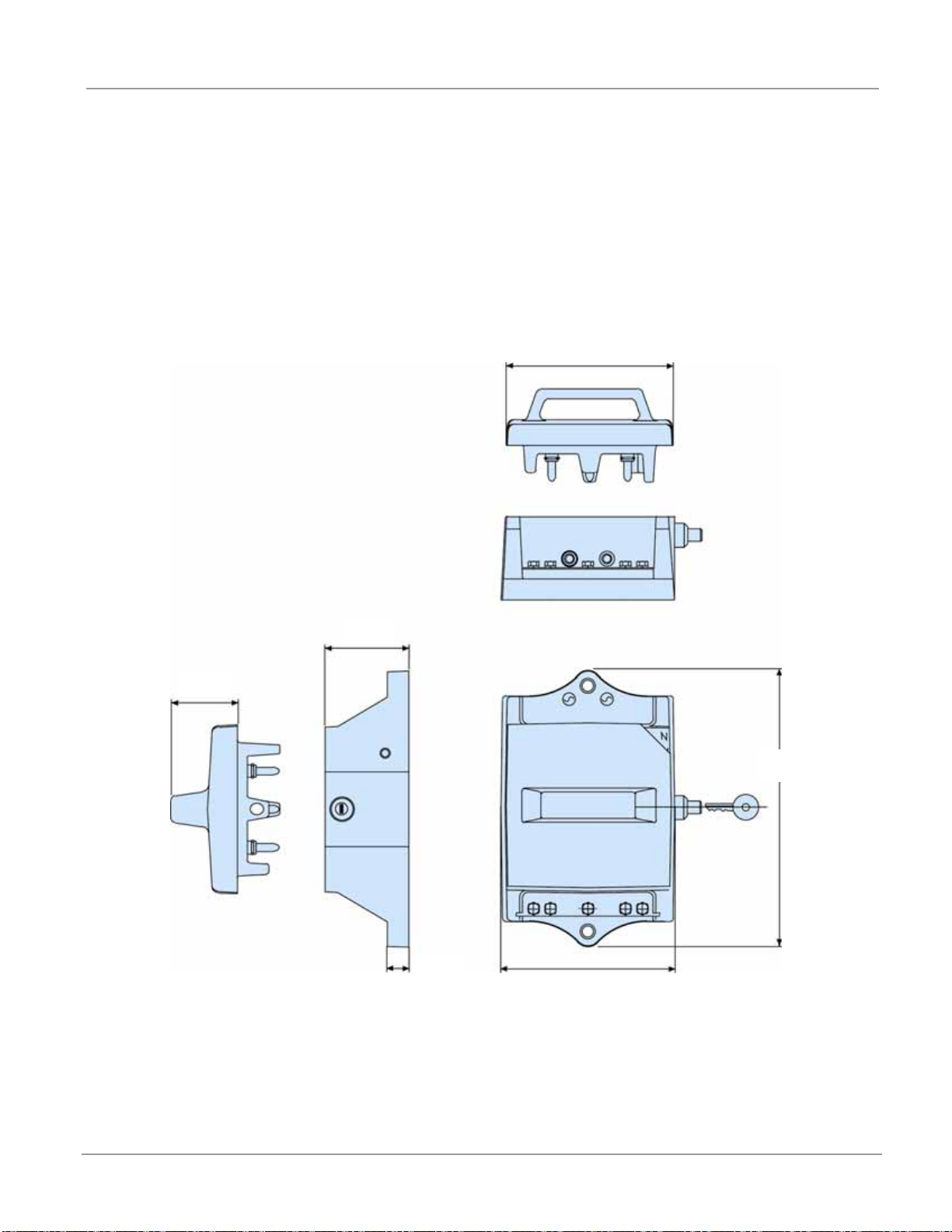
Dimensions: See Figure 4 for SCO cutout dimensions.
Figure 4: SCO Cutout Dimensions
2.4 in.
(60 mm)
5.1 in. (130 mm)
5.5 in. (140 mm)
0.63 in.
(16 mm)
2.1 in.
(46 mm)
8.7 in.
(220 mm)

Series Cutout (SCO)
Installation
© ADB Airfield Solutions All Rights Reserved
10
96A0294 Rev. G
2.4 Installation
2.4.1 Introduction
This section provides installation instructions for the SCO cutout. It includes equipment unpacking, individual cutout installation,
cutout wiring, and pre-installed cutout installation. Wiring instructions for pre-installed cutouts are provided in Pre-Installed
Cutout Installation in this section.
A cutout can be installed individually on or close to a constant current regulator (CCR). It can also be incorporated inside other
equipment. Examples would be in a bay on a SwitchGear regulator system or internal to a ADB Airfield Solutions Signature
SeriesTM CCR. It can also be incorporated inside other equipment.
2.4.2 Unpacking
The equipment is shipped ready for installation. Handle equipment very carefully to prevent component damage. Unpack the
carton upon receipt and check the contents and their condition. Note any exterior damage to the carton that might lead to
detection of equipment damage.
If you note any damage to any equipment, file a claim with the carrier immediately.
The carrier may need to inspect the equipment.
The carton contains the following:
2.4.3 Individual Cutout Installation
This subsection provides information about installing individual SCO cutouts. It includes individual cutout mounting and wiring. It
also includes pre-installed cutout installation.
2.4.3.1 Individual Cutout Mounting
The series cutout can be installed in the vault substation, in the vicinity of the CCR to which it is connected. For example,
the cutout can be mounted in the following ways:
•On the wall or rack (Unistrutor similar type of channel) beside the CCR
•In a “Field Junction Box” containing a large number of cutouts
•In a separate enclosure beside the CCR
In case L-847 circuit selectors are used, the cutouts may be used on either side (input or output) of the selectors, but preferably
on the output side (one cutout for each series circuit). Some installations use a cutout on both the input and outputs of the L-
847.
Before mounting the SCO cutout, determine if the interlock switch will be used. See Figure 11 for application information for
interlocking with the CCR. If the interlock is used, determine how the wiring for the CCR remote control terminal block will be
routed. The wire can be routed through the mounting plate or through the body of the SCO cutout. Guidance for routing
through the mounting plate is shown in Figure 5. Figure 6 provides guidance for routing through the SCO body.
NOTE: If the interlock switch is wired from behind the panel (in line with the interlock switch), then drill a hole as shown in figure
5. Be sure to de-bur the hole and place a spiral wrap around the wire leads.
WARNING
Allow only qualified personnel to perform the following tasks. Observe and follow the safety instructions in this
document and all other related documentation.
•SCO cutout
•Two keys
•Handle Position decal
•Read Manual decal
•Instruction Manual
WARNING
• When using the SCO cutout with a circuit selector, the regulator must be turned off and locked out before
performing any insulation resistance measurements. To operate the regulator without erratic results, all SCO cutouts
must be returned to the normal operating position.
• To test the regulator under short circuit conditions, all SCO cutouts after the circuit selector must be in the test &
measurement position.

© ADB Airfield Solutions All Rights Reserved
11
If the interlock switch is wired by cutting the thin wall in the cutout body (see Figure 6, Item 3), then drill the hole in the lower right
portion of the plate outside the perimeter of the cutout and use a conventional grommet to protect the wire leads.
CAUTION
• Mount the SCO cutout only on a flat, level surface. Do not mount the SCO cutout directly on a UnistrutTM channel or
other similar channels. Mounting the cutout on a Unistrut channel may cause the ear of the cutout to crack since the
channel is unsupported. If you must install the cutout on a Unistrut channel, fasten a customer-supplied ¼-in.-thick
mounting plate to the channel and then fasten the cutout to the plate. See Figure 5 for a drilling template.
Series Cutout (SCO)
Installation
© ADB Airfield Solutions All Rights Reserved
12
96A0294 Rev. G
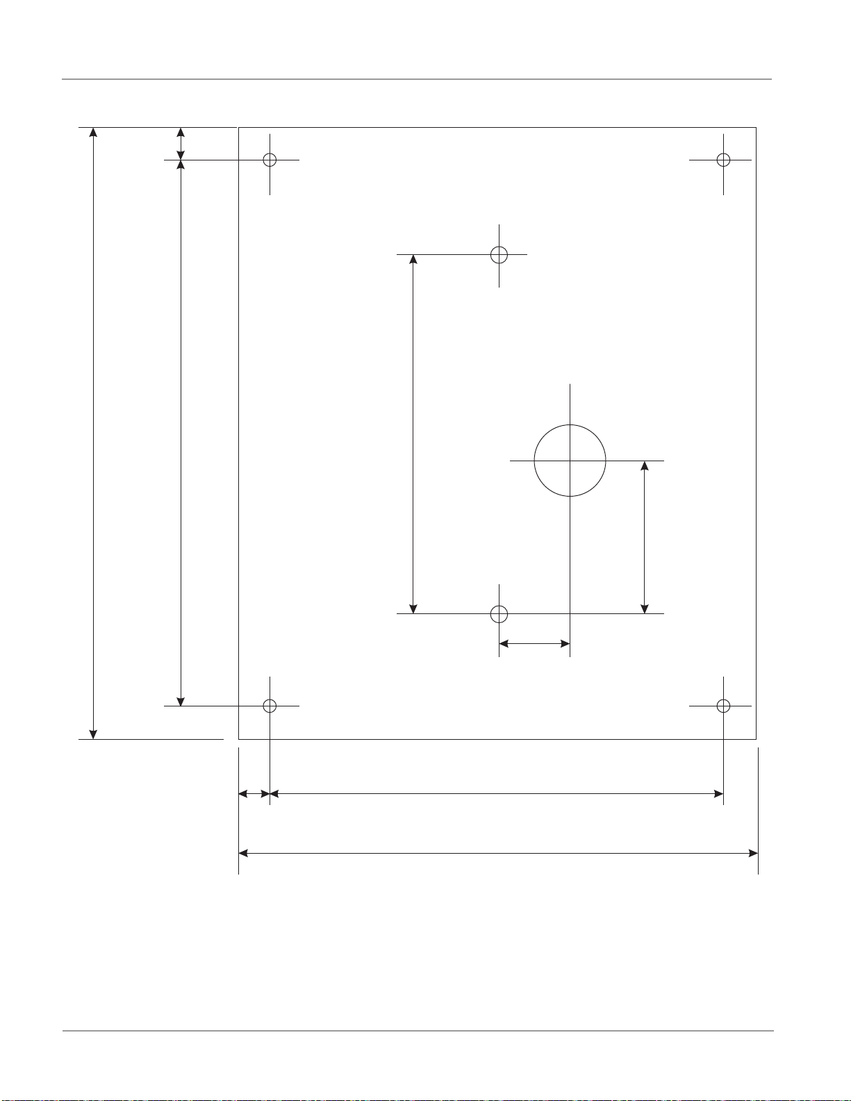
Figure 5: Drilling Template
NOTE: See Figure 6 for the location of the interlock switch on the cutout. Suggested optional interlock switch wire location may
vary according to wire routing method.
0.688 - inch
0.688 - inch
9.62 - inch
11.0 - inch
13.0 - inch
11.625 - inch
7.66 - inch
1.75 - inch
2.25 - inch
15/64 Drill Thru
(4 places)
Drill and Tap
3/8 - 16 UNC-2B Thru
(2 Places)
1.50 - inch Diameter
optional location through
mounting plate
(see Note)
194.49 mm
38.10 mm
5.95 mm
17.46 mm
17.46 mm
44.45 mm
57.15 mm
9.52 mm
330.20 mm
295.27 mm
244.47 mm
279.40 mm
© ADB Airfield Solutions All Rights Reserved
13
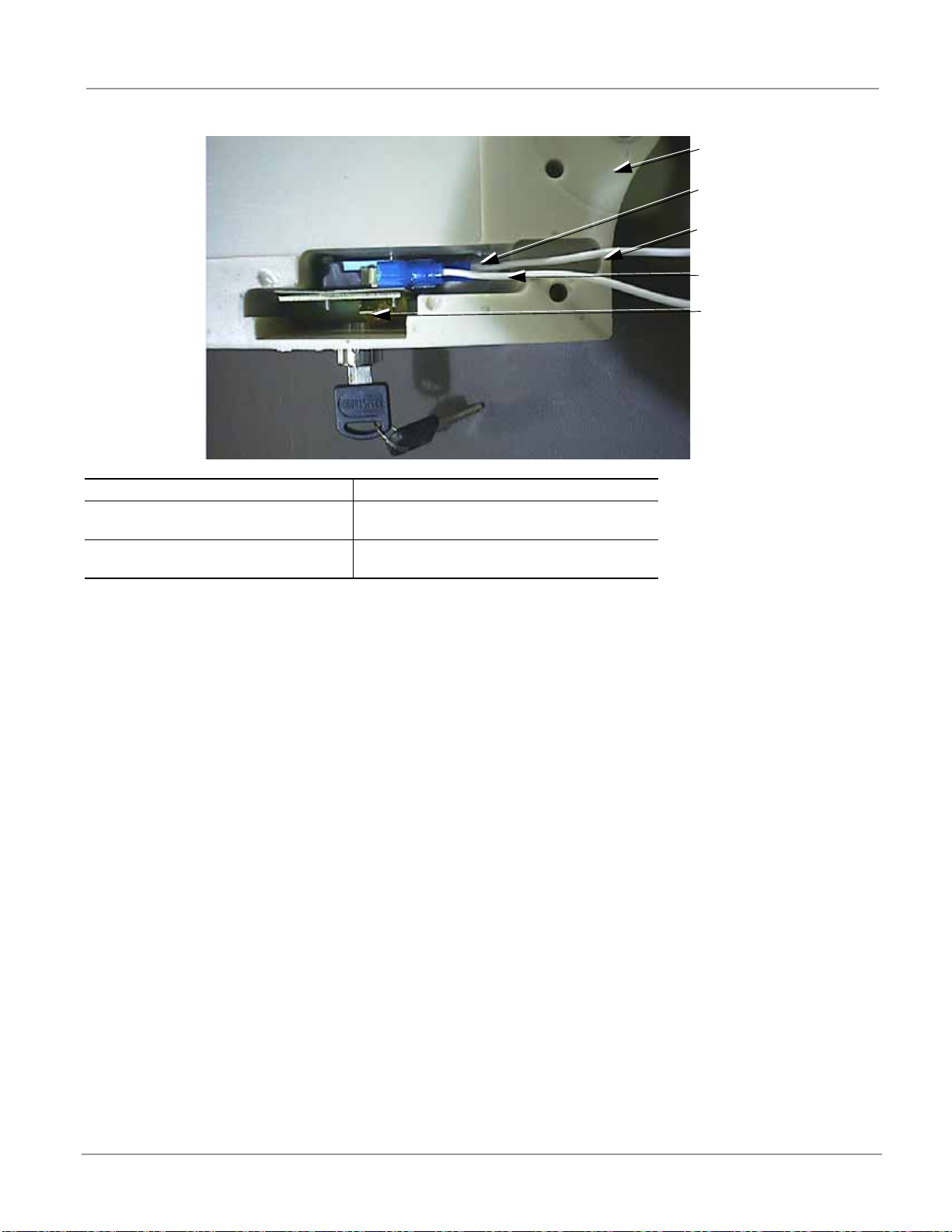
Figure 6: Connecting Wires to Interlock Switch Terminals (If Used)
Individual SCO cutouts are normally mounted on a plate or in a NEMA enclosure. Multiple cutouts can also be mounted side-by-
side on a plate or in a NEMA enclosure.
2.4.3.2 Mounting Individual Cutouts on Plate
To mount an individual SCO cutout on a plate, perform the following procedure:
1. Create a slot or hole for the spade connectors if the interlock switch is wired through the back of the panel as shown in
Figure 5.
NOTE: If the switch is wired from the front side of the mounting plate, cut a thin wall found at the end of the molded channel as
shown in Figure 6, Item 3.
2. Drill two holes on the plate, and tap 3/8−16 x 1 UNC as shown in Figure 5.
3. See Figure 7. Mount the cutout on the plate using two 3/8 −16 x 1 long hex head cap screws and two 3/8 flat washers or lock
washers.
1. Bottom of Cutout 4. Interlock Switch Wiring to Terminal for W
2. Interlock Switch Wiring to Terminal for
NO
5. Optional Interlock Switch Shield Terminal (If
Used)
3. Cut Out Thin Wall to Bring through
Interlock Wire (Optional)
1
2
3
4
5

Series Cutout (SCO)
Installation
© ADB Airfield Solutions All Rights Reserved
14
96A0294 Rev. G
Figure 7: Mounting Cutout on Plate
1. SCO Cutout
2. Mounting Plate
3. Screws and Lockwashers for Mounting Cutout
1
2
3
Table of contents


