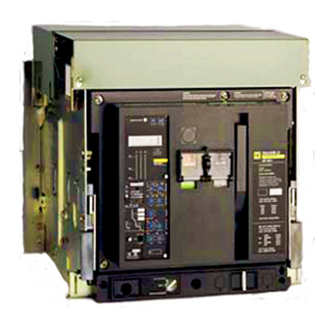
Merlin Gerin Masterpact MP-MC User manual

Masterpact
installation
instructions
universal power
breaker
TM
O
push OFF
MERLIN GERIN
MP20
H1
masterpact
connected
test
disconnected
OOPEN discharged
I
push ON
circuit breaker
3 pole
600V 50/60Hz
frame size 2000A
suitable for continious operation
at 100% rating in a minimum cubical
space H17.5 by W21 by D14.1/4 inches
ventilation is not required
interrupting rating
max RMS sym amps
Volts
240
480
600
short time rating 75KA
Amps
75K
75K
75K
IEC957-2690V50/60Hz
interruptingrating
Icu380/440V75KA
660V75KA
Icu380/440V75KA
660V75KA
short timerating
Icw=75KA0.5 sec.
push to reset
I
I1 I2 I3
90%
50%
20%
STR 58 U
Ir
90
105%Ir
.88.9.92
.95
.98
1
.8
.85
xIo
Im tm
3456
8
10
1.5
2
xIo
.3.4.
3
.1
.1
.2
onI
2
toff
.2
0
Irfault
tr
Imfault
tm
I
fault
Ih
th
t
i
test
+S–
– T +
T
F
Ih th
400500600800
1000
1200
250
320
A
.3.4.4
.2
.1
.2
onI
2
toff
.3
.1
I
off
2
xIn
Ir :
Im :
th :
IIGL
I
G
L
LG
LIG
off
reset V
tr
60120240
480
15
30
at1,5Ir
4
6812
17
22
Ic1 Ic2
.86
.9.93.95
.98
1
.8
.85
.7.8.
85
.95
.5
.6
xIr
.9
1
R
xIr
test
Io=3000A
cat.no.54775
formasterpact
withsensorsIn=6000A
E63335
UND. LAB. O List.
CIRCUIT BREAKER
Doles. IssueN°LM-8792
00000
MERLIN GERIN
mastering electrical power

689 994B - 15/10/94
1MERLIN GERIN
Masterpact MP-MC circuit breaker
TM
page
table of contents
installation
introduction 2
tools needed 2
recommendation for storing 2
identifying your Masterpact 3
unpacking 4
handling 6
attaching rear terminals 9
control wiring 11
operation
disconnecting instructions 13
installing the breaker in its stationary assembly 15
connecting instructions 16
charging instructions 17
closing instructions 17
opening instructions 17
resetting instructions 17
locking 18
refer to technical manual for :
■control units
■ time-current curves
■ wiring diagrams
■ dimensions
■ maintenance
■ endurances

Masterpact MP-MC circuit breaker
689 994B - 15/10/94
MERLIN GERIN2
TM
introduction
Instructions are to be followed when
receiving the breaker and before installing it.
tools needed
■hex key wrenches
■straight blade scewdriver (large and
small)
■wire stripper
recommendations for sto-
ring
it is not recommended to store the breakers
in corrosive or salt laden environment.
Temperature limits :
from -60°F (-50°C) min to +160°F
(+70°C)max
Breaker status :
■main contacts open
■spring discharged
■connected position
Do not store breaker without its original
shipping carton or any protective covering.
2
Stacking :
maximum permitted :
MP08 to MP30
MP40 to MP63

689 994B - 15/10/94
3MERLIN GERIN
Masterpact MP-MC circuit breaker
TM
3
identifying your Masterpact
location of markingsTM
circuit breaker frame
stationary assembly
electrical accesories
identification label
(fixed mounting)
name label giving rating,
interrupting ratings
and rated voltage
order number - position - date
standard or specific diagram
no. sensor rating
instantaneous pickup
electrical accesories
identification label
frame size
standard or specific diagram no.
order number - position - date

Masterpact MP-MC circuit breaker
689 994B - 15/10/94
MERLIN GERIN4
TM
unpacking
MP08 to MP30
Breakers are screwed on their palett by
means of 4 bolts.
With drawout mounting, it is necessary to
withdraw and remove the breaker to have
access to the bolts.
fixed mounted
4
drawout mounted
disconnect the breaker (see page 12)
and remove it from its stationary assembly
(see page 13)
remove bolts, nuts and washers
drawout mounted without stationary assembly
pull the two handgrips to extract the breaker
remove the four bolts
remove the 4 shipping bolts
breaker is delivered upside down. Place
another palett next to shipping palett. Rotate
breaker onto terminals, then onto its bottom
on second palett

689 994B - 15/10/94
5MERLIN GERIN
Masterpact MP-MC circuit breaker
TM
5
unpacking (cont'd)
MP08 to MP30
stationary assembly only
MP40 to MP63 drawout mounted
∂remove the 4 shipping bolts
∑
position another wooden palett and rotate the frame
∏remove the plastic
caps
breaker is delivered upside down. Place
another palett next to shipping palett. Rotate
breaker onto terminals, then onto its bottom
on second palett
circuit breaker frame
remove the 4 shipping bolts
stationary assembly
remove the tape holding the clusters (if any)

Masterpact MP-MC circuit breaker
689 994B - 15/10/94
MERLIN GERIN6
TM
frame alone
handling
MP08 to MP30 - MC08 to MC20
The Masterpact frame and its stationary
assembly are provided with lateral handles
in order to facilitate lifting.
Before handling it is suggested to remove
the breaker from its stationary assembly.
See page 13 for operation.
External or overhead lifting device can use
the lateral handles for lifting the circuit
breaker as shown.
Weights (lbs/
kg
)
stationary frame terminals
assembly
MP08 51 /
23
102 /
46
13 /
6
➀
MP12 51 /
23
102 /
46
13 /
6
➀
MP16 51 /
23
102 /
46
13 /
6
MP20 60 /
27
121 /
55
36 /
16
MP25 110 /
50
176 /
80
89 /
40
MP30 110 /
50
176 /
80
89 /
40
MC08 51 /
23
102 /
46
13 /
6
➀
MC16 51 /
23
102 /
46
13 /
6
MC20 60 /
27
121 /
55
36 /
16
➀optional terminals
using the lateral handles
frame alone
caution:
to avoid damage to the stationary assembly
do not let the forks of the fork lift protrude
past the rear of the breaker.
stationary assembly alone
using a lifting sling
slings :
.40 dia max.
Ø 10 mm max.
frame alone stationary assembly alone
using a fork lift

689 994B - 15/10/94
7MERLIN GERIN
Masterpact MP-MC circuit breaker
TM
handling (cont'd)
MC32
An external or overhead lifting device can
use the lateral handles for lifting the circuit
breaker as shown.
Weights (lbs/
kg
)
stationary frame
assembly
MC32 254 /
115
198 /
90
frame alone (compensation bar not supplied-hooks can be supplied on request)
stationary assembly alone (compensation bar not supplied-hooks can be supplied on request)
using a lifting sling
slings :
.40 dia max.
Ø 10 mm max.
stationary assembly alone
caution:
lift the stationary assembly enough to avoid
any shock between the load terminals and
the cubicle cell.
using a fork lift
2 slings : .40 dia max.
Ø 10 mm max.
1 sling : .40 dia max. 58.8 long max.
Ø 10 mm max. lg = 1500 mm max.

Masterpact MP-MC circuit breaker
689 994B - 15/10/94
MERLIN GERIN8
TM
30" min.
800mm min.
handling (cont'd)
MP40 to MP63
An external or overhead lifting device can
use the lateral handles for lifting the circuit
breaker as shown.
Weights (lbs/
kg
)
stationary frame terminals
assembly
MP40 198 /
90
264 /
120
88 /
40
➀
MP50 198 /
90
264 /
120
177 /
80
MP63 242 /
110
308 /
140
177 /
80
➀optional terminals
7
using a lifting sling
slings :
.40 dia max.
Ø 10mm max.
frame alone
stationary assembly alone
using a fork lift
frame alone
caution:
to avoid damage to the stationary assembly
do not let the forks of the fork lift protrude
past the rear of the breaker.
stationary assembly alone
caution:
to avoid capsizing the stationary assembly
place a chock as shown. Remove it as soon
as the ends of forks lean on the cubicle floor.
.
30" min.
800mm min.
2"
50 mm
1,2"
30 mm

689 994B - 15/10/94
9MERLIN GERIN
Masterpact MP-MC circuit breaker
TM
8
drawout mounted
drawout mounted
drawout mounted
MP08 - MP12 - MP16
fixed mounted
MP20
fixed mounted
MP25 - MP30
fixed mounted
TM
screws M10, 60mm long
11/16 hex head wrench may be used
attaching rear terminals
The terminals provided with the Masterpact
shall be mounted as indicated below :
MP08 - MP20
screws M10, 60mm long
tightening torque = 375 lb.in.
11/16 hex head wrench may be used
MP25 - MP30
fixed mounted
drawout mounted

Masterpact MP-MC circuit breaker
689 994B - 15/10/94
MERLIN GERIN10
TM
attaching rear terminals
(cont'd)
MC32
drawout mounted
MP40 - MC40
drawout mounted
MP40
fixed mounted
oror
MP50 - MP63 - MC50
drawout mounted
MP50
fixed mounted

689 994B - 15/10/94
11MERLIN GERIN
Masterpact MP-MC circuit breaker
TM
1
control wiring
Each terminal may be connected by one
stranded copper wire 18 to 14 AWG (0.6 to
2.5 mm2)
Cable strip length : 3/8" /
9mm
fixed mounting
1install the connector
2remove the transparent shield
3connect the control wires according to
the wiring diagrams shown on the label and
using a small screwdriver
4replace the transparent cover
warning : do not route the control wires
close to the arc chutes
3
4
2
10

Masterpact MP-MC circuit breaker
689 994B - 15/10/94
MERLIN GERIN12
TM
control wiring (cont'd)
drawout mounting
1remove the front terminal cover
2determine the terminal number ➀
according to the wiring label ➁
3connect the control wires using a small
screwdriver and replace the front terminal
cover
4 warning : do not route the control wires
close to the arc chutes
1
11
2
34
location of terminals
note : Z = Z - W Control unit (left hand side) Accessories (right hand side)

689 994B - 15/10/94
13MERLIN GERIN
Masterpact MP-MC circuit breaker
TM
12
disconnecting
and connecting instruc-
tions
All Masterpact circuit breakers have four
drawout positions and can be operated in
these four positions. The circuit breaker is
captive in all positions except "withdrawn".
To connect or disconnect the Masterpact
circuit breaker, first insert the of racking
crank.
Insertion of the racking crank can be
prevented by the following stationary
assembly accessories:
■padlock
■key-lock
■racking interlock
note : Disconnecting and connecting
instructions are summarized on a sticker
provided with the installation instructions .
The sticker must be affixed to the door of the
CONNECTED position
TEST position
DISCONNECTED position
WITHDRAWN position
cubicle .■In the CONNECTED
position, the primary and secondary
disconnecting terminals are engaged, and
the circuit breaker is ready for service.
■In the TEST position, the primary
terminals are disengaged; however, control
contacts are connected to permit operation
of the circuit breaker. The TEST position is
used for testing circuit breaker operation and
control system functions as provided. In this
position, the circuit breaker is not suitable for
internal inspection or any maintenance
function.
■In the DISCONNECTED position, the
primary and secondary disconnect terminals
are disengaged and separated by a safe
distance from the corresponding stationary
terminals
■In the WITHDRAWN position, both
primary and secondary contacts are
disconneted. The circuit breaker may be
removed for complete accessibility.
note: a racking crank maintened inserted or
breaker not completely disconnected
prevents the extraction of the right rail.
notes :
■a closed circuit breaker is automatically
opened prior to being connected or
disconnected during a racking in or racking
out operation.
■the circuit breaker may be operated in all
four positions.

Masterpact MP-MC circuit breaker
689 994B - 15/10/94
MERLIN GERIN14
TM
1
2
disconnecting instructions
note: open the breaker before disconnecting
it. Otherwise it will open automatically during
disconnection.
3
5
13
1remove the racking crank from its
storage hole and engage it in the racking
slot
note : in case of racking interlock, press the
"compartment door closed" sensor located at
the front of the drawout mechanism to
simulate a closed door.
2to reach the test position then
disconnected position turn the racking crank
anticlockwise until the test and disconnected
indication are shown on the position
indicator
3 caution : The racking handle must be
removed before pulling out the breaker,
otherwise the right rail will not fully extend
4pull the two handgrips to extract the
breakers
5use the two lateral handles to remove
the frame from its stationary assembly. See
other means of handling page 6
4

689 994B - 15/10/94
15MERLIN GERIN
Masterpact MP-MC circuit breaker
TM
12
3
14
installating the breaker in
its stationary assembly
note : a racking handle remaining inserted
in its racking slot or a breaker not fully
disconnected prevents the extraction of the
right rail
1pull the two extension rails by their
handles
2install the breaker on the two extension
rails making sure that the four breaker
supports located on the two sides of the
circuit breaker are correctly engaged in the
slots. See page 6 for other means of
handling
3to move the breaker from the WITH-
DRAWN position to the DISCONNECTED
position, push the breaker into the stationary
assembly until it stops.
As a safety feature, the racking crank cannot
be engaged if the breaker is not in the
DISCONNECTED position.
caution : do not press on the control unit
while pushing the breaker in.

Masterpact MP-MC circuit breaker
689 994B - 15/10/94
MERLIN GERIN16
TM
1
32
15
connecting instructions
1engage racking crank into its racking slot
note : the operation is possible only if :
❑breaker is in DISCONNECTED position
❑drawout mechanism padlocks have been
removed
❑Kirk key lock has been unlocked
❑compartment door is closed
note : in case of racking interlock, press the
"compartment door closed" sensor located at
the front of the drawout mechanism to
simulate a closed door
2turn the racking crank clockwise until the
CONNECTED position is reached on the
position indicator
warning : as the fully connected position is
neared, more force will be necessary to turn
the crank. Continue cranking until two "click"
sounds are heard (locking the breaker in the
connected position)
3remove the racking crank and put it back
in its storage hole

689 994B - 15/10/94
17MERLIN GERIN
Masterpact MP-MC circuit breaker
TM
charging instructions
All basic breaker and drawout operations
can be performed from the front of the
breaker.
Suitable electrical and mechanical interlocks
are provided to prevent incorrect operation
of the breaker. Manually operated breakers
have multiple charge-close provisions which
allow the following possible operating
sequence : charge-close-recharge-open-
close-open.
To manually charge an electrically or
manually operated breaker, push or pull
down on the charging handle. The handle is
shaped to make manual charging easy,
when the breaker is located in either a low or
high position within a switchboard enclosure.
Six full strokes can be used. When the
spring is fully charged, the yellow "charged"
indicator will appear in the stored energy
window on the breaker front cover.
When the mechanism is fully charged, the
handle stops and will return to normal
position when released.
Manually Electrically
closing instructions
All that is required to close the breaker
locally is to push the mechanical "Push-to-
close" pushbutton. Pre-charged breakers
may be closed remotely via a spring release
solenoïd which is standard for electrically
operated breakers and optional for manually
operated breakers.
Before attempting to close the breaker
locally, the yellow stored energy window
indicator must read "charged".
note :
■ The closing coil (XF) withstands a
continuous voltage, providing antipumping
function. If the breaker is not ready to close
when the closing order is intended, inhibit it
and try again as soon as the breaker is
ready to close
■ to inhibit the antipumping function, wire in
series the ready-to-close switch (terminals
251 - 252) with the closing coil.
opening instructions
Opening the breaker locally is accomplished
with the mechanical "Push to open"
pushbutton on the breaker front cover .
Breakers may be opened remotely via either
a shunt trip or an undervoltage trip device
depending upon the application require-
ments.
16
resetting instructions
The mechanical fault indicator indicates
that an overcurrent has occured and
prevents reclosure of the circuit breaker until
reset.
caution : in case of tripping due to overcur-
rent or ground fault, the fault must be
cleared before any attempt of resetting
Breaker can be closed only if :
■it is opened
■charged
■pop-out type fault indicator is correcly
reset
■no opening order is intended

123456789101112131415161718
19 20 21 22 23 20 20 20 20
page 2
tools needed
■hex key wrenches
■straight blade scewdriver (large and
small)
■wire stripper
page 5
remove the tape holding the clusters (if any)
page 6
handling
MP08 to MP30 - MC08 to MC20
The Masterpact frame and its stationary
assembly are provided with lateral handles
in order to facilitate lifting.
Before handling it is suggested to remove
the breaker from its stationary assembly.
See page 13 for operation.
External or overhead lifting device can use
the lateral handles for lifting the circuit
breaker as shown.
page 7
rod .48 dia.
Ø 12 mm
Weights (lbs/
kg
)
stationary frame
assembly
MC32 254 /
115
198 /
90
2 slings : .40 dia max.
Ø 10 mm max.
1 sling : .40 dia max. 58.8 long max.
Ø 10 mm max. lg = 1500 mm max.
stationary assembly alone
caution:
lift the stationary assembly enough to avoid
any shock between the load terminals and
the cubicle cell.
page 9
screws M10, 60mm long
tightening torque = 375 lb.in.
11/16 hex head wrench may be used
screws M10, 60mm long
11/16 hex head wrench may be used
1remove the racking crank from its
storage hole and engage it in the racking
slot
note : in case of racking interlock, press the
"compartment door closed" sensor located at
the front of the drawout mechanism to
simulate a closed door.
2to reach the test position then
disconnected position turn the racking crank
anticlockwise until the test and disconnected
indication are shown on the position
indicator
3 caution : The racking handle must be
removed before pulling out the breaker,
otherwise the right rail will not fully extend
4pull the two handgrips to extract the
breakers
5use the two lateral handles to remove
the frame from its stationary assembly. See
other means of handling page 6
page 14
Shackle diameter : 1/4" to 5/16"
page 18
couverture
MERLIN GERIN
mastering electrical power
sommaire
8 9 10111213141516171819202020202020

MERLIN GERIN
12
page 5
remove the tape holding the clusters (if any)
Table of contents
Other Merlin Gerin Circuit Breaker manuals