GE MicroVersaTrip Plus User manual

••
.
GEH
-
5891
A
WARNINGS
,
CAUTIONS
,
AND
NOTES
AS
USED
IN
THIS
PUBLICATION
WARNINGS
Warning
notices
are
used
in
this
publication
to
emphasize
that
hazardous
voltages
,
cur
-
rents
,
or
other
conditions
that
could
cause
personal
injur
)
'
exist
in
this
equipment
or
may
be
associated
with
its
use
.
Warning
notices
are
also
used
for
situations
in
which
inattention
or
lack
of
equipment
knowledge
could
cause
either
personal
injuiy
or
damage
to
equipment
.
CAUTIONS
Caution
notices
are
used
for
situations
in
which
equipment
might
be
damaged
if
care
is
not
taken
.
NOTES
(
•
•
fV
)
V
Notes
call
attention
to
information
that
is
especially
significant
to
understanding
and
operating
the
equipment
.
This
document
is
based
on
information
available
at
the
time
of
its
publication
.
While
efforts
have
been
made
to
ensure
accuracy
,
the
information
contained
herein
does
not
cover
all
details
or
variations
in
hardware
and
software
,
nor
does
it
provide
for
every
pos
-
sible
contingency
in
connection
with
installation
,
operation
,
and
maintenance
.
Features
may
be
described
herein
that
are
not
present
in
all
hardware
and
software
systems
.
GE
Electrical
Distribution
8
c
Control
assumes
no
obligation
of
notice
to
holders
of
this
docu
-
ment
with
respect
to
changes
subsequently
made
.
GE
Electrical
Distribution
8
c
Control
makes
no
representation
or
warranty
,
expressed
,
implied
,
or
statutory
,
with
respect
to
,
and
assumes
no
responsibility
for
the
accuracy
,
completeness
,
sufficiency
,
or
usefulness
of
the
information
contained
herein
.
No
warran
-
tees
of
merchantability
or
fitness
for
purpose
shall
apply
.
The
following
are
trademarks
of
GE
Company
:
MicroVersaTrip
®
Plus
,
MicroVersaTrip
®
PM
,
Power
Break
®
,
Spectra
RMS
,
Epic
.
K
.
:
V
)
©
Copyright
1993
GE
Company
All
Rights
Reserved
t
Courtesy of NationalSwitchgear.com

Micro
Versa
Trip
®
Pius
and
Micro
Versa
Trip
®
PM
Trip
Units
Table
of
Contents
Chapter
1
.
Introduction
1
-
1
Read
This
First
1
-
2
Product
Structure
1
-
3
Trip
Unit
Functions
1
-
4
Trip
Unit
Catalog
Numbers
1
-
5
Rating
Plugs
1
-
6
Equipment
Interfaces
MicroVersaTrip
Plus
Trip
Units
......
.
.
.
...
Neutral
Current
Sensors
MicroVersaTrip
PM
Trip
Units
POWER
LEADER
Communication
Network
Voltage
Inputs
Power
Requirements
1
-
7
Trip
Unit
Information
Trip
Unit
Label
Information
Function
Keys
Liquid
Crystal
Display
1
-
8
MicroVersaTrip
Plus
and
MicroVersaTrip
PM
Accuracies
1
1
2
2
3
3
3
4
4
4
4
5
5
5
5
6
6
Chapter
2
.
Setup
Mode
7
2
-
1
Overview
2
-
2
Operating
Modes
2
-
3
Setup
Mode
Operation
Long
-
Time
Pickup
Long
-
Time
Delay
Short
-
Time
Pickup
Short
-
Time
Delay
Instantaneous
Pickup
High
-
Range
Instantaneous
Overcurrent
Protection
Ground
-
Fault
Pickup
Ground
-
Fault
Delay
Voltage
-
Unbalance
Relay
Pickup
Voltage
-
Unbalance
Relay
Delay
Current
-
Unbalance
Relay
Pickup
Current
-
Unbalance
Relay
Delay
Undervoltage
Relay
Pickup
Undervoltage
Relay
Delay
Overvoltage
Relay
Pickup
Overvoltage
Relay
Delay
Power
-
Reversal
Relay
Pickup
Power
-
Reversal
Relay
Delay
Rating
Plug
Current
Setting
7
8
13
13
13
14
14
15
15
16
.
_
>
16
16
17
17
17
17
17
18
18
18
18
•
11
Courtesy of NationalSwitchgear.com

Micro
Versa
Trip
®
Plus
and
Micro
Versa
Trip
®
PM
Trip
Units
Table
of
Contents
.
*
:
*
Potential
Transformer
Primary
Voltage
Potential
Transformer
Connection
Communication
Address
19
19
19
Chapter
3
.
Metering
Mode
20
3
-
1
Overview
.
3
-
2
Metering
Mode
Operation
Current
Voltage
Energy
Real
Power
Total
Power
Frequency
20
22
22
22
22
23
23
Chapter
4
.
Status
Mode
24
4
-
1
Overview
.
4
-
2
Status
Mode
Operation
Normal
Status
Display
Long
-
Time
Overcurrent
Pickup
and
Target
Displays
Short
-
Time
Overcurrent
Target
Display
Instantaneous
Target
Display
Ground
-
Fault
Target
Display
Protective
-
Relay
Target
Displays
Clearing
the
Target
After
Trip
24
24
24
/
•
'
A
24
24
25
.
25
25
Chapter
5
.
Maintenance
and
Trouble
-
Shooting
5
-
1
Trip
Unit
Removal
and
Replacement
POWER
BREAK
Insulated
-
Case
Circuit
Breakers
Type
AKR
Low
-
Voltage
Power
Circuit
Breakers
..
.
5
-
2
Rating
Plug
Removal
and
Replacement
5
-
3
Trouble
-
Shooting
Guide
26
26
26
26
26
t
•
v
•
*
•
111
Courtesy of NationalSwitchgear.com

Micro
Versa
Trip
®
Plus
and
Micro
Versa
Trip
®
PM
Trip
Units
List
of
Figures
1
.
Front
view
of
MicroVersaTrip
PM
trip
unit
2
.
Rear
view
of
MicroVersaTrip
PM
tt
'
ip
unit
.
3
.
Function
key
placement
on
face
of
trip
unit
4
.
Liquid
crystal
display
segments
5
.
Operation
of
FUNCTION
key
,
showing
progression
among
trip
unit
operating
modes
.
6
.
Trip
unit
setup
mode
programming
function
flow
7
.
Trip
unit
display
for
long
-
time
pickup
8
.
Time
-
current
curve
illustrating
long
-
time
pickup
9
.
Trip
unit
display
for
long
-
time
delay
10
.
Time
-
current
curve
illustrating
long
-
time
delay
11
.
Trip
unit
display
for
short
-
time
pickup
12
.
Time
-
current
curve
illustrating
short
-
time
pickup
13
.
Trip
unit
display
for
short
-
time
delay
14
.
Time
-
current
curve
for
short
-
time
delay
with
l
2
T
OUT
15
.
Time
-
current
curve
for
short
-
time
delay
with
l
2
T
IN
;
16
.
Trip
unit
display
for
instantaneous
pickup
17
.
Instantaneous
overcurrent
protection
set
point
18
.
Trip
unit
display
for
ground
-
fault
pickup
19
.
Time
-
current
curve
for
ground
-
fault
pickup
20
.
Trip
unit
display
for
ground
-
fault
delay
21
.
Time
-
current
curve
for
ground
-
fault
delay
with
l
2
T
OUT
22
.
Time
-
current
curve
for
ground
-
fault
delay
with
l
2
T
IN
23
.
Trip
unit
display
for
voltage
-
unbalance
relay
pickup
24
.
Trip
unit
display
for
voltage
-
unbalance
relay
delay
25
.
Trip
unit
display
for
current
-
unbalance
relay
pickup
26
.
Trip
unit
display
for
current
-
unbalance
relay
delay
27
.
Trip
unit
display
for
undervoltage
relay
pickup
28
.
Trip
unit
display
for
undervoltage
relay
delay
29
.
Trip
unit
display
for
overvoltage
relay
pickup
30
.
Trip
unit
display
for
overvoltage
relay
delay
31
.
Trip
unit
display
for
power
-
reversal
relay
pickup
32
.
Trip
unit
display
for
power
-
reversal
relay
delay
33
.
Trip
unit
display
for
rating
plug
current
set
point
34
.
Trip
unit
display
for
potential
transformer
primary
voltage
set
point
35
.
Trip
unit
display
for
potential
transformer
connection
choice
36
.
Trip
unit
display
for
setting
communication
address
37
.
Trip
unit
metering
mode
function
flow
38
.
Trip
unit
display
for
current
metering
39
.
Trip
unit
display
for
line
-
to
-
neutral
voltages
1
2
5
6
8
9
13
13
13
13
14
14
14
14
14
15
15
15
15
©
16
16
16
16
17
17
17
17
17
17
18
18
18
18
19
19
19
20
22
22
i
;
i
IV
Courtesy of NationalSwitchgear.com

Micro
Versa
Trip
®
Pius
and
Micro
Versa
Trip
®
PM
Trip
Units
List
of
Figures
\
L
'
22
40
.
Trip
unit
display
for
line
-
to
-
line
voltages
.
41
.
Trip
unit
display
for
aggregate
energy
42
.
Trip
unit
display
for
real
power
with
line
-
to
-
neutral
connections
43
.
Trip
unit
display
for
aggregate
real
power
with
line
-
to
-
line
connections
.
44
.
Trip
unit
display
for
total
power
with
line
-
to
-
neutral
connections
45
.
Trip
unit
display
for
aggregate
total
power
with
line
-
to
-
line
connections
46
.
Trip
unit
display
for
frequency
in
each
phase
47
.
Trip
unit
display
for
normal
status
48
.
Trip
unit
status
display
for
long
-
time
overcurrent
pickup
49
.
Trip
unit
status
display
for
long
-
time
overcurrent
trip
50
.
Trip
unit
status
display
for
short
-
time
overcurrent
trip
51
.
Trip
unit
status
display
for
ground
-
fault
trip
52
.
Trip
unit
status
display
for
protective
-
relay
trip
...
,
22
22
22
23
23
23
24
24
24
24
25
25
f
;
.
:
:
A
•.
V
Courtesy of NationalSwitchgear.com

Micro
Versa
Trip
®
Plus
and
Micro
Versa
Trip
®
PM
Trip
Units
List
of
Tables
1
.
Trip
unit
catalog
number
prefixes
and
corresponding
current
sensor
ratings
2
.
Trip
unit
catalog
number
suffixes
for
optional
functions
3
.
MicroVersaTrip
PM
trip
unit
suffixes
for
communication
,
metering
,
and
relaying
4
.
Rating
plug
catalog
numbers
5
.
Protective
relay
and
metering
accuracies
and
resolutions
6
.
Abbreviations
used
in
setup
procedure
descriptions
7
.
Actions
of
function
keys
in
trip
unit
operating
modes
8
.
Nominal
delays
for
long
-
time
delay
bands
9
.
Nominal
delays
for
i
2
t
out
short
-
time
delay
bands
10
.
Ground
-
fault
pickup
settings
,
as
a
function
of
sensor
rating
11
.
Nominal
delays
for
ground
-
fault
delay
bands
12
.
Trip
unit
rating
plug
options
13
.
Trip
unit
display
codes
for
protective
relays
2
3
3
4
6
7
8
13
14
15
16
18
25
w
VX
Courtesy of NationalSwitchgear.com

Micro
Versa
Trip
®
Plus
and
MicroVersaTrip
®
PM
Trip
Units
Chapter
1
.
Introduction
1
-
1
Read
This
First
The
MicroVersaTrip
®
Plus
and
MicroVersaTrip
®
PM
trip
units
described
in
this
publication
are
used
on
both
Power
Break
®
insulated
-
case
and
Type
AKR
low
-
voltage
power
circuit
breakers
.
Spectra
/
IMS
molded
-
case
circuit
breakers
use
different
versions
of
MicroVersaTrip
Plus
and
MicroVersaTrip
PM
trip
units
that
are
not
interchangeable
with
the
units
described
here
.
Refer
to
GEH
-
5934
for
information
on
these
trip
units
.
Testing
of
MicroVersaTrip
Plus
and
MicroVersaTrip
PM
trip
units
may
be
performed
with
the
trip
unit
installed
in
the
circuit
breaker
,
the
rating
plug
installed
in
the
trip
unit
,
and
the
breaker
carrying
current
.
The
test
set
catalog
number
is
TVRMS
.
The
test
set
plugs
into
the
test
socket
of
the
rating
plug
.
Test
set
TVRMS
may
also
be
used
for
MicroVersaTrip
RMS
-
9
and
Epic
MicroVersaTrip
trip
units
.
Refer
to
the
Maintenance
and
Troubleshooting
section
for
additional
details
.
1
'
•
4
Figure
1
.
Front
view
of
MicroVersaTrip
PM
trip
unit
.
1
-
2
Product
Structure
MicroVersaTrip
Plus
and
MicroVersaTrip
PM
trip
units
are
removable
.
Figures
1
and
2
contain
front
and
rear
views
of
a
MicroVersaTrip
PM
trip
unit
.
CAUTION
:
Removal
of
the
rating
plug
while
the
breaker
is
carrying
current
reduces
the
breaker
’
s
current
-
carrying
capacity
to
approximately
25
%
of
Figure
2
shows
the
36
-
pin
plug
that
connects
either
the
current
sensor
rating
.
This
may
result
in
unde
-
trip
unit
to
the
circuit
breaker
and
equipment
cir
-
sired
tripping
.
cuitry
.
This
plug
is
called
the
trip
unit
disconnect
.
CAUTION
•
Removal
of
a
trio
unit
from
its
breaker
N
0
TE
*
TriP
UnitS
aS
received
may
have
settings
that
SSwxth
^
hTbrXr
inTe
OPFN
or
are
undesirable
for
the
-
Pedfic
aPPdcation
.
Ensure
TRIPPED
position
.
Draw
-
out
breakers
should
be
*
at
setun
85
arc
Rusted
before
ener
-
racked
out
first
.
Sizing
.
CAUTION
:
Do
not
attempt
to
operate
the
breaker
without
its
assigned
trip
unit
.
Installation
of
an
incorrect
trip
unit
may
result
in
unsafe
operation
of
the
breaker
.
•
•
,
V
1
Courtesy of NationalSwitchgear.com

Micro
Versa
Trip
®
Pius
and
Micro
Versa
Trip
®
PM
Trip
Units
Chapter
1
.
Introduction
m
-
High
-
range
(
fixed
)
instantaneous
overcurrent
protection
-
Short
-
time
protection
,
with
or
without
I
2
T
-
Ground
-
fault
protection
,
with
or
without
I
2
T
-
Zone
-
selective
interlock
,
with
ground
fault
only
or
with
both
ground
fault
and
short
time
Additional
optional
functions
available
only
with
JPM
style
trip
units
are
as
follows
.
PM
style
trip
units
require
the
presence
of
external
control
power
.
•
Configurations
-
Communication
and
metering
-
Communication
and
protective
relaying
-
Communication
,
metering
,
and
protective
relaying
•
Metering
and
protective
-
relaying
functions
-
Voltage
-
Energy
(
kWh
/
MWh
)
-
Real
power
(
kW
/
MW
)
-
Total
power
(
kVA
/
MVA
)
-
Frequency
(
Hz
)
-
Protective
relays
(
undervoltage
,
overvoltage
,
voltage
unbalance
,
current
unbalance
,
and
power
reversal
)
0
i
*
VvvS
'
v
>
Figure
2
.
Rear
view
of
MicroVersaTrip
PM
trip
unit
.
1
-
3
Trip
Unit
Functions
1
-
4
Trip
Unit
Catalog
Numbers
MicroVersaTrip
Plus
and
MicroVersaTrip
PM
trip
units
have
specific
standard
and
optional
functions
.
All
trip
units
share
a
series
of
interchangeable
rating
-
plugs
.
The
standard
functions
for
both
types
of
trip
unit
are
as
follows
:
•
Protection
-
Long
-
time
protection
-
Instantaneous
protection
A
simple
catalog
numbering
system
defines
all
of
the
standard
and
optional
trip
unit
functions
.
The
pre
-
fixes
tliat
determine
the
allowable
current
sensor
rat
-
ings
hre
listed
in
Table
1
.
One
of
these
is
present
on
all
trip
unit
catalog
numbers
.
Immediately
following
this
prefix
is
the
letter
L
,
indicating
long
-
time
over
-
current
protection
.
•
Status
-
Trip
target
•
Metering
display
-
Phase
current
(
selectable
among
phases
)
The
optional
functions
available
on
both
types
of
trip
unit
are
as
follows
:
•
Adjustable
protection
-
Switchable
instantaneous
and
ground
-
fault
protection
(
Type
AKR
only
)
Current
Sensor
Ampere
Ratings
Power
Break
Prefix
AKR
200
,
400
,
800
,
1000
,
1600
,
2000
150
,
400
,
600
,
800
,
1600
,
2000
TT
20
2500
,
3000
TT
32
3200
TT
40
4000
4000
Table
1
.
Trip
unit
catalog
number
prefixes
and
corresponding
current
sensor
ratings
.
2
'
A
Courtesy of NationalSwitchgear.com

Micro
Versa
Trip
®
Pius
and
Micro
Versa
Trip
®
PM
Trip
Units
Chapter
1
.
Introduction
Additional
letters
are
appended
to
the
catalog
num
-
ber
to
indicate
installed
protective
functions
,
as
in
Table
2
.
These
suffixes
are
valid
for
both
Plus
and
(
blank
)
-
MicroVersaTrip
Plus
PM
style
trip
units
.
They
are
appended
from
left
to
J
.
5
Rating
Plugs
right
in
the
order
given
.
Interchangeable
rating
plugs
are
used
to
establish
or
change
the
current
rating
of
the
breaker
.
Rating
plugs
for
MicroVersaTrip
Plus
or
MicroVersaTrip
PM
trip
units
in
either
Power
Break
or
Type
AKR
break
-
ers
are
interchangeable
within
the
same
sensor
rat
-
ing
.
Rating
plugs
for
Power
Break
and
Type
AKR
breakers
can
not
be
interchanged
with
Spectra
RMS
MicroVersaTrip
Plus
and
MicroVersaTrip
PM
trip
units
.
A
built
-
in
rejection
feature
prevents
the
insertion
of
a
rating
plug
with
an
incorrect
sensor
rating
into
a
trip
unit
.
Likewise
,
a
Spectra
RMS
rating
plug
can
not
be
inserted
into
a
Power
Break
or
Type
AKR
breaker
.
Rating
plug
catalog
numbers
are
listed
in
Table
4
.
Protective
Function
Suffix
Short
-
time
overcurrent
S
I
Instantaneous
over
cur
rent
Fixed
high
-
range
instantaneous
H
Ground
fault
G
Z
1
or
Zone
-
selective
interlock
:
Z
1
-
ground
fault
only
Z
2
-
ground
fault
and
short
time
High
-
range
instantaneous
(
AKR
-
30
S
only
)
Z
2
K
Switchable
instantaneous
and
ground
fault
(
AKR
only
)
X
Table
2
.
Trip
unit
catalog
number
suffixes
for
optional
functions
.
MicroVersaTrip
PM
catalog
numbers
contain
an
additional
one
-
or
two
-
letter
suffix
to
indicate
the
1
-
6
Equipment
interfaces
-
iV
communication
,
metering
,
and
relaying
functions
MicroVersaTrip
Plus
Trip
Units
installed
,
as
shown
in
Table
3
.
MicroVersaTrip
Plus
catalog
numbers
do
not
have
this
final
suffix
.
MicroVersaTrip
Plus
trip
units
do
not
usually
require
connections
within
the
equipment
,
since
all
wiring
is
contained
within
the
circuit
breaker
.
The
only
two
connections
are
for
optional
zone
-
selective
interlock
(
Z
1
and
Z
2
)
,
made
by
secondary
disconnect
,
and
the
neutral
sensor
,
which
uses
a
special
dedicated
dis
-
connect
.
Zone
-
selective
interlocking
coordinates
breakers
,
so
that
the
downstream
breaker
is
allowed
the
first
opportunity
to
clear
a
disturbance
.
The
two
types
of
zone
-
selective
interlocking
available
are
Zl
,
which
reacts
only
to
ground
faults
,
and
Z
2
,
.
which
reacts
to
both
ground
faults
and
short
-
time
overcurrent
pickups
.
Suffix
Function
MicroVersaTrip
Plus
trip
unit
(
none
)
PM
Metering
,
relaying
,
and
communication
Metering
and
communication
M
Relaying
and
communication
P
Table
3
.
MicroVersaTrip
PM
trip
unit
suffixes
for
communica
-
tion
,
metering
,
and
relaying
.
For
example
,
a
trip
unit
with
catalog
number
TT
32
LSIG
has
the
following
functions
:
TT
32
-
trip
unit
for
sensor
greater
than
2000
and
up
to
3200
amperes
.
L
-
long
-
time
overcurrent
protection
S
-
short
-
time
overcurrent
protection
I
-
standard
instantaneous
protection
G
-
ground
-
fault
protection
v
.
-
v
R
.
*
-
-
V
3
Courtesy of NationalSwitchgear.com

Micro
Versa
Trip
®
Pius
and
MicroVersaTrip
®
PM
Trip
Units
Chapter
1
.
Introduction
'
51
r
Sensor
Rating
,
Amps
Plug
Rating
Breaker
Frames
Neutral
Current
Sensors
Cat
.
No
.
TR
1
B
60
TR
1
B
80
TR
1
B
100
TR
1
B
125
TR
1
BI
50
60
CAUTION
:
Neutral
current
sensors
are
required
for
three
-
phase
,
four
-
wire
systems
.
When
the
trip
unit
is
connected
to
a
three
-
phase
,
three
-
wire
system
,
the
neutral
sensor
terminals
are
left
open
.
Do
not
short
any
neutral
current
sensor
terminals
in
a
three
-
phase
,
three
-
wire
system
,
as
this
could
result
in
dam
-
age
to
or
malfunction
of
the
electrical
system
.
80
AKR
30
S
,
AXR
30
H
150
100
125
150
TR
2
B
100
TR
2
B
150
TR
2
B
200
100
200
150
TP
82
,
THP
82
TC
82
,
THC
82
200
TR
4
B
150
TR
4
B
200
TR
4
B
225
TR
4
B
250
TR
4
B
300
TR
4
B
400
150
200
400
225
TP
84
,
THP
84
TC
84
,
THC
84
AKR
30
S
,
AKR
30
H
250
MicroVersaTrip
PM
Trip
Units
In
addition
to
the
inputs
received
by
MicroVersaTrip
Plus
trip
units
,
MicroVersaTrip
PM
trip
units
also
receive
inputs
from
external
voltage
conditioners
,
a
24
Vdc
control
power
supply
,
and
communication
connections
.
External
24
Vdc
control
power
is
required
for
operation
.
PM
style
trip
units
are
also
connected
to
an
auxiliary
switch
within
the
breaker
that
senses
the
breaker
position
.
300
400
TR
8
B
300
TR
8
B
400
TR
8
B
450
TR
8
B
500
TR
8
B
600
TR
8
B
700
TR
8
B
800
300
400
450
TP
88
,
THP
88
TC
88
,
THC
88
AKR
30
S
,
AKR
30
H
AKR
50
S
,
AKR
50
H
800
500
600
700
800
TR
10
B
400
TR
10
B
600
TR
10
B
800
TR
10
B
900
TR
10
B
1000
400
600
TC
2510
,
THC
2510
TP
1610
,
THP
1610
TP
2510
,
THP
2510
1000
800
900
1000
TR
16
B
600
TR
16
B
800
TR
16
B
1000
TR
16
B
1100
TR
16
B
1200
TR
16
B
1600
600
POWER
LEADER
Communication
Network
The
POWER
LEADER
Communication
Network
(
commnet
)
transmits
data
and
instructions
between
the
trip
unit
and
an
external
intelligent
device
.
The
external
device
may
be
the
POWER
LEADER
system
,
the
Epic
system
,
or
a
POWER
LEADER
Monitor
.
Devices
on
commnet
may
be
up
to
1000
feet
apart
without
signal
repeaters
,
subject
to
certain
con
-
straints
.
Commnet
connections
are
made
directly
to
wiring
terminations
on
breaker
frames
.
All
commnet
con
-
nections
to
the
trip
units
are
made
through
the
36
-
pin
plug
on
the
trip
unit
,
which
mates
with
a
recep
-
tacle
on
the
breaker
frame
.
These
additional
connec
-
tions
are
made
to
the
equipment
through
the
sec
-
ondary
disconnect
of
the
breaker
.
800
1000
TC
1610
,
THC
1610
AKR
50
S
,
AKR
50
H
TP
1616
,
THP
1616
1600
1100
1200
1600
TR
20
B
750
TR
20
B
800
TR
20
B
1000
TR
20
B
1200
TR
20
B
1500
TR
20
B
1600
TR
20
B
2000
750
800
TC
2020
,
THC
2020
TC
2520
,
THG
2520
TP
2020
,
THP
2020
TP
2520
,
THP
2520
AKRT
50
H
1000
2000
1200
1500
1600
2000
TR
25
B
1600
TR
25
B
2000
TR
25
B
2500
1600
2500
2000
TC
2525
,
THC
2525
TP
2525
,
THP
2525
2500
TR
30
B
2000
TR
30
B
2500
TR
30
B
3000
2000
2500
3000
TC
3030
,
THC
3030
TP
3
Q
30
,
THP
3030
3000
TR
32
B
1200
TR
32
B
1600
TR
32
B
2400
TR
32
B
3200
1200
1600
3200
2400
AKR
75
3200
TR
40
B
1600
TR
40
B
2000
TR
40
B
2500
TR
40
B
3000
TR
40
B
3600
TR
40
B
4000
1600
2000
Voltage
Inputs
Voltage
inputs
are
sensed
by
conventional
instru
-
ment
potential
transformers
(
PTs
)
.
PTs
have
120
Vac
secondaries
and
must
always
be
used
in
threes
;
no
open
-
delta
connections
are
permitted
.
PT
primaries
are
connected
either
line
-
to
-
line
or
line
-
to
-
neutral
,
as
required
.
2500
TC
4040
,
THC
4040
TP
4040
,
THP
4040
4000
3000
3600
4000
Table
4
.
Rating
plug
catalog
numbers
.
4
Courtesy of NationalSwitchgear.com

Micro
Versa
Trip
®
Pius
and
MicroVersaTrip
®
PM
Trip
Units
Chapter
1
.
Introduction
V
PTs
may
be
used
for
other
monitoring
functions
,
subject
to
reasonable
burden
limitations
.
Note
that
PTs
must
be
connected
in
a
specific
sequence
to
ensure
proper
phase
relations
and
power
-
flow
sensing
.
Each
PT
output
feeds
an
individual
voltage
condi
-
tioner
that
scales
the
nominal
voltage
to
approxi
-
mately
1.76
Vac
.
•
Top
right
comer
-
replacement
trip
unit
order
number
,
such
as
TT
09
N
031
,
and
date
-
of
-
manu
-
facture
code
of
the
trip
unit
,
such
as
E
301
=
.
•
Top
left
of
display
-
catalog
number
of
the
trip
unit
,
such
as
TT
32
LSPM
.
•
Top
right
of
display
-
sensor
rating
of
the
trip
unit
,
such
as
SENSOR
=
1600
A
.
•
Below
display
-
indicates
whether
the
unit
is
MicroVersaTrip
Plus
or
MicroVersaTrip
PM
.
There
are
two
more
labels
on
the
trip
unit
that
are
not
generally
visible
when
it
is
plugged
into
a
breaker
.
•
Top
of
unit
-
another
date
code
and
a
bar
code
,
used
for
manufacturing
only
.
•
Rear
of
unit
~
yellow
caution
label
.
Power
Requirements
A
small
amount
of
power
is
necessary
to
energize
the
liquid
crystal
display
(
LCD
)
during
setup
,
for
viewing
breaker
status
,
and
for
metering
displays
.
MicroVersaTrip
PM
trip
units
require
external
24
Vdc
control
power
for
operation
.
The
four
sources
of
such
power
are
the
following
.
•
Flow
of
current
-
Breaker
current
sensors
provide
sufficient
power
to
energize
the
LCD
when
at
least
20
%
of
the
sensor
’
s
ampere
rating
is
flowing
.
Function
Keys
There
are
four
function
keys
on
the
trip
units
,
marked
FUNCTION
,
SELECT
,
VALUE
,
and
ENTER
,
as
•
24
Vdc
control
poxoer
-
Breakers
with
illustrated
in
Figure
3
.
All
setup
,
status
,
and
metering
MicroVersaTrip
PM
trip
units
are
supplied
with
functions
and
displays
are
accessed
through
these
external
24
Vdc
power
that
,
whenever
present
,
keys
.
Control
power
is
necessary
to
operate
function
energizes
the
LCD
.
Some
breaker
models
that
keys
.
However
,
as
each
set
point
is
entered
,
it
is
are
configured
for
MicroVersaTrip
Plus
trip
stored
in
the
trip
unit
’
s
nonvolatile
memory
,
so
sub
-
units
may
be
optionally
equipped
to
accept
an
sequent
loss
of
power
does
not
lose
or
change
any
settings
.
external
24
Vdc
supply
.
•
MicroVersaTrip
Test
Kit
-
The
MicroVersaTrip
Test
Kit
,
Cat
No
.
TVRMS
,
contains
a
24
Vdc
power
supply
.
The
LCD
is
energized
whenever
the
test
kit
jack
is
plugged
into
the
test
recepta
-
cle
on
the
rating
plug
.
•
MicroVersaTrip
battery
pack
-
The
portable
MicroVersaTrip
battery
pack
contains
a
24
Vdc
power
source
and
a
jack
.
The
LCD
is
energized
when
the
jack
is
plugged
into
the
rating
plug
test
receptacle
.
m
mm
ip
!
i
IB
FUNCTION
SELECT
5
vsassas
gSSjj
:::::::::
:
VALUE
ENTER
Figure
3
.
Function
key
placement
on
face
of
trip
unit
.
The
functions
of
the
four
keys
are
•
FUNCTION
-
selects
the
mode
of
display
.
•
SELECT
-
chooses
the
next
item
for
display
.
•
VALUE
-
selects
the
phase
-
to
-
phase
display
or
allows
changing
of
set
points
.
•
ENTER
-
stores
set
points
.
Chapter
2
describes
the
operation
of
these
keys
in
detail
.
7
-
7
Trip
Unit
Information
Trip
Unit
Label
Information
Following
are
descriptions
of
the
various
labels
on
the
front
of
the
trip
unit
,
as
shown
in
Figure
1
.
•
Top
left
comer
-
serial
number
of
the
unit
,
such
as
LBA
000393
.
V
-
.
5
Courtesy of NationalSwitchgear.com

Micro
Versa
Trip
®
Pius
and
Micro
Versa
Trip
®
PM
Trip
Units
Chapter
1
.
Introduction
m
V
.
vi
'
Refer
to
trip
-
time
curves
in
GES
-
9865
(
AKR
)
,
GES
-
9866
(
Power
Break
and
R
-
Frame
)
,
and
GES
-
9863
(
ground
fault
)
for
accuracies
of
overcurrent
protec
-
tion
.
Liquid
Crystal
Display
Figure
4
illustrates
the
LCD
with
all
segments
illumi
-
nated
.
The
various
segments
are
energized
in
response
to
conditions
sensed
by
the
trip
unit
.
Full
-
Scale
Accuracy
1
-
8
Micro
Versa
Trip
Plus
and
Micro
Versa
Trip
PM
Accuracies
The
accuracy
data
in
Table
5
represent
the
average
expected
performance
of
MicroVersaTrip
Plus
and
MicroVersaTrip
PM
trip
units
,
together
with
their
associated
current
sensors
,
rating
plugs
,
potential
transformers
,
and
voltage
modules
.
These
data
are
valid
for
setup
,
metering
,
and
status
mode
displays
.
They
include
the
effects
of
trip
unit
ambient
-
temper
-
ature
variation
from
0
°
C
to
70
°
C
.
All
percentages
are
based
on
full
-
scale
values
.
Full
-
scale
current
is
X
,
the
rating
of
the
breaker
’
s
rating
plug
.
Full
-
scale
voltage
is
the
potential
transformer
primary
voltage
rating
.
These
data
do
not
include
the
accuracy
rating
of
any
measuring
instrument
.
Resolution
Value
±
2
%
±
0.5
digit
Current
(
A
,
kA
)
±
1.5
%
Voltage
(
V
)
±
0.5
digit
±
3.5
%
Energy
(
kWh
,
MWh
)
±
0.5
digit
±
3.5
%
Real
power
(
kW
,
MW
)
±
0.5
digit
±
3.5
%
Total
power
(
kVA
,
MVA
)
±
0.5
digit
Frequency
(
Hz
)
±
1
Hz
±
1
Hz
Time
delay
(
sec
)
±
1
sec
±
1
sec
Table
5
.
Protective
relay
and
metering
accuracies
and
resolutions
.
H
.
HH
VOLTS
AMPS
ABC
SETUP
S
X
C
STATUS
METER
kA
kWh
mW
mWh
kW
Hz
ORT
CIRCUIT
GF
NORMAL
LTIME
STIME
INST
GF
l
2
T
IN
l
2
T
OUT
VU
CU
UV
OV
PR
VL
-
L
VL
-
N
ENGY
PICKUP
DELAY
PWR
FREQ
PF
Figure
4
.
Liquid
crystal
display
segments
.
6
Courtesy of NationalSwitchgear.com

Micro
Versa
Trip
®
Plus
and
Micro
Versa
Trip
®
PM
Trip
Units
Chapter
2
.
Setup
Procedures
)
/
-
V
'
X
2
-
2
Operating
Modes
2
-
1
Overview
This
chapter
describes
the
operation
of
the
four
MicroVersaTrip
Plus
and
MicroVersaTrip
PM
trip
function
keys
,
set
point
and
time
-
delay
adjustments
,
units
have
three
operating
modes
:
Status
,
Metering
,
and
their
accuracies
.
The
setup
procedures
should
and
Setup
.
The
effects
of
each
of
the
four
function
only
be
repeated
if
the
trip
unit
or
the
protection
keys
in
each
mode
are
listed
in
Table
7
.
characteristics
are
changed
,
requiring
different
set
points
and
time
delays
.
All
the
function
keys
,
except
for
ENTER
,
automati
-
cally
step
the
trip
unit
display
to
the
next
available
These
procedures
apply
to
MicroVersaTrip
Plus
and
option
each
time
the
key
is
pressed
.
Continued
press
-
MicroVersaTrip
PM
trip
units
.
Setup
programming
ing
of
a
key
eventually
loops
the
display
back
to
the
must
be
performed
with
the
rating
plug
installed
.
initial
option
for
that
function
.
This
is
illustrated
in
Figure
5
for
the
FUNCTION
key
,
which
shows
that
repeatedly
pressing
this
key
cycles
the
mode
among
Status
,
Metering
,
and
Setup
.
Pressing
the
ENTER
key
more
than
once
has
no
effect
.
For
trip
units
set
up
through
either
the
POWER
LEADER
system
or
the
Epic
MicroVersaTrip
Field
Programming
Unit
,
refer
to
instructions
published
for
those
systems
.
Table
6
contains
a
list
of
abbreviations
used
throughout
the
description
of
the
setup
procedures
.
Depressing
the
VALUE
key
for
about
5
seconds
acti
-
vates
a
fast
scan
that
rapidly
displays
each
of
the
available
set
points
or
time
delays
for
some
of
the
trip
characteristics
.
Abbr
.
Description
Rating
plug
ampere
rating
.
X
S
Current
sensor
ampere
rating
.
Long
-
time
(
LT
)
setting
in
amperes
.
Multiply
LT
set
point
by
rating
plug
amperes
(
A
)
.
C
Short
-
time
(
ST
)
withstand
rating
of
breaker
in
amperes
.
H
100
%
total
power
setting
of
power
-
reversal
relay
.
Delta
:
Q
=
1.732
x
100
%
Vx
X
/
1000
kVA
Wye
:
3
-
0
*
100
%
Vx
A
71000
kVA
6
FUNCTION
key
on
face
of
trip
unit
.
F
SELECT
key
on
face
of
trip
unit
.
S
VALUE
key
on
face
of
trip
unit
.
V
ENTER
key
on
face
of
trip
unit
.
E
Table
6
.
Abbreviations
used
in
setup
procedure
descriptions
.
t
V
7
Courtesy of NationalSwitchgear.com

Micro
Versa
Trip
®
Pius
and
MicroVersaTrip
®
PM
Trip
Units
Chapter
2
.
Setup
Procedures
Trip
Unit
Operating
Mode
Key
Symbol
Setup
Metering
Status
Select
one
of
three
modes
:
Setup
,
Metering
,
Status
FUNCTION
F
Select
next
programming
display
Select
next
metering
display
No
effect
S
SELECT
Display
next
set
-
point
or
time
-
delay
value
Display
next
phase
value
No
effect
V
VALUE
Store
set
-
point
or
time
-
delay
value
into
memory
No
effect
No
effect
E
ENTER
Table
7
.
Actions
of
function
keys
in
trip
unit
operating
modes
.
F
F
F
SETUP
STATUS
METER
Figure
5
.
Operation
of
FUNCTION
key
,
showing
progression
among
trip
unit
operating
modes
.
2
-
3
Setup
Mode
Operation
unit
display
.
Ignore
setup
mode
instructions
for
such
functions
.
The
trip
unit
must
be
provided
with
control
power
during
setup
.
This
can
come
from
a
MicroVersaTrip
Test
Kit
,
a
MicroVersaTrip
battery
pack
,
external
24
Vdc
power
supply
,
or
energizing
the
breaker
to
at
least
20
%
of
its
sensor
load
.
To
begin
the
process
,
press
the
FUNCTION
k
|
y
until
SETUP
appears
in
the
upper
-
right
corner
of
the
trip
unit
’
s
LCD
.
Setup
mode
always
begins
with
long
-
time
pickup
.
After
a
choice
has
been
made
for
this
and
each
subsequent
trip
function
,
press
SELECT
to
advance
to
the
next
function
.
The
following
instructions
describe
setup
procedures
for
all
available
trip
unit
functions
.
These
are
illus
-
trated
in
Figure
6
.
All
trip
units
provide
long
-
time
overcurrent
,
long
-
time
delay
,
and
some
form
of
instantaneous
overcurrent
protection
when
installed
in
Power
Break
circuit
breakers
.
All
other
functions
are
optional
,
If
a
specific
set
of
trip
unit
functions
,
such
as
relaying
or
short
-
time
overcurrent
protection
,
has
not
been
ordered
,
that
function
will
not
appear
on
the
trip
i
-
T
-
r
:
W
8
Courtesy of NationalSwitchgear.com

Micro
Versa
Trip
®
Pius
and
MicroVersaTrip
®
PM
Trip
Units
Chapter
2
.
Setup
Mode
m
r
>
/
V
KEY
:
JFj
FUNCTION
Si
STATUS
[
V
]
VALUE
~
El
ENTER
F
F
F
METER
SETUP
STATUS
*
Setting
Choices
0.50
X
to
1.1
OX
,
steps
of
0.05
X
SETUP
1
X
Long
-
Time
Pickup
V
V
V
“
0.55
-
1.05
1.10
0.50
LTIME
s
No
Other
Setting
Choices
SETUP
*
Long
-
Time
Delay
!
V
3
V
-
4
V
-
2
V
LTIME
DELAY
S
Setting
Choices
1
,
5
C
to
9.0
C
,
steps
of
,
5
C
SETUP
I
5
Q
c
Short
-
Time
Pickup
V
V
-
2.00
—
v
—
8.50
9.00
1.50
-
A
•
M M
k
-
•
'
y
STIME
PICKUP
s
*
«
§
ETUP
t
Short
-
Time
Delay
v
vv
—
3
2
l
2
T
IN
STIME
DELAY
No
Other
Setting
Choices
SETUP
I
2
3
VV
V
STIME
|
!
T
OUT
DELAY
Setting
Choices
1.5
X
to
15
,
OX
,
in
steps
of
0.5
X
,
with
maximum
dependent
on
frame
rating
itoKv
S
SETUP
X
Inst
.
V
—
2.0
14.5
-
V
1.5
Pickup
INST
PICKUP
(
A
)
Continued
on
next
page
Figure
6
.
Trip
unit
setup
mode
programming
function
flow
.
9
Courtesy of NationalSwitchgear.com

Micro
VersaTrip
®
Plus
and
Micro
VersaTrip
®
PM
Trip
Units
Chapter
2
.
Setup
Mode
A
S
E
SETUP
Sensor
Ratings
150
-
600
A
s
Ground
-
Fault
Pickup
.
20
V
-
.
21
.
59
.
60
v
v
GF
PICKUP
10
—
r
^
Hv
]
20
j
—
[
V
lQHvhT
2
i
T
37
|
—
[
\
71
2500
-
3200
A
29
j
—
|
VHIQ
-
—
(
V
|
4000
A
s
B
a
No
Other
Setting
Choices
SETUP
I
Ground
-
Fault
Delay
\
v
v
-
2
3
V
GF
l
!
T
IN
DELAY
(
Additional
OFF
setting
for
X
option
.
)
SETUP
2
V
V
V
3
GF
in
OUT
DELAY
s
Setting
Choices
10
to
50
%
,
in
increments
of
1
%
r
^
-
E
I
!
]
SETUP
Voltage
-
Unbalance
Pickup
10
—
V
—
11
V
V
49
50
VU
PICKUP
s
Setting
Choices
1
to
15
sec
,
off
increments
of
1
sec
SETUP
H
s
Voltage
-
Unbalance
Delay
V
-
2
—
15
V
V
—
~
t
HUB
VU
s
Setting
Choices
10
to
50
%
,
in
increments
of
1
%
SETUP
IE
Current
-
Unbalance
Pickup
10
-
V
49
-
V
V
11
50
Mas
cu
PICKUP
(
B
)
Continued
on
next
page
Figure
6
.
Trip
unit
setup
mode
programming
function
flow
(
continued
)
.
10
-
-
-
V
-
Courtesy of NationalSwitchgear.com

Micro
Versa
Trip
®
Plus
and
Micro
Versa
Trip
®
PM
Trip
Units
Chapter
2
.
Setup
Mode
KEY
:
[
~
F
~
|
FUNCTION
~
sl
STATUS
FVI
VALUE
~
E
]
ENTER
B
S
Setting
Choices
1
to
15
-
sec
,
off
increments
of
1
sec
SETUP
E
$
Current
-
Unbalance
Delay
v
v
OFF
-
V
2
-
15
HUB
cu
DELAY
s
Setting
Choices
50
to
90
%
,
in
increments
of
1
%
SETUP
Under
-
Voltage
Pickup
v
V
V
50
51
-
89
90
BOB
uv
PICKUP
Setting
Choices
1
to
15
sec
,
off
increments
of
1
sec
i
-
E
B
SETUP
S
Under
-
Voltage
Delay
5
V
—
OFF
V
-
2
V
M
»
uv
DELAY
Setting
Choices
110
to
150
%
,
in
increments
of
1
%
s
I
55
SETUP
Over
-
Voltage
Pickup
v
150
-
V
110
111
I
149
V
ov
PICKUP
s
Setting
Choices
1
to
15
sec
,
off
increments
of
1
sec
IE
SETUP
S
Over
-
Voltage
Delay
1
-
V
14
-
V
—
OFF
-
V
2
a
OV
DELAYi
s
Setting
Choices
0.01
to
3.00
Q
,
in
increments
of
.
01
Q
E
n
i
SETUP
Power
-
Reversal
Pickup
.
u
i
2.99
—
V
.
01
V
V
-
02
—
3.00
n
a
a
PR
PICKUP
(
C
)
Continued
on
next
page
Figure
6
.
Trip
unit
setup
mode
programming
function
flow
(
continued
)
.
V
*
11
Courtesy of NationalSwitchgear.com

Chapter
2
.
Setup
Mode
s
Setting
Choices
1
to
15
sec
,
off
increments
of
1
sec
in
SETUP
S
Power
-
Reversal
Delay
iu
v
V
1
-
V
-
2
15
PR
DELAY
*
Setting
Choices
60
,
80
,
100
,
126
,
150
,
200
,
225
,
250
,
300
,
400
,
460
,
600
,
600
,
700
,
750
,
800
,
1000
,
1200
,
1500
,
1600
,
2000
,
2500
,
3000
,
3200
,
3600
,
4000
.
s
SETUP
AMPS
X
Rating
V
—
80
|
-
3600
|
-
—
1
\
7
|
—
14000
V
60
N
M
B
Plug
s
Setting
Choices
120
to
600
volts
increments
of
1
V
VOLTS
SETUP
Potential
Transformer
Primary
Voltage
v
600
1211
599
120
V
V
s
SETUP
VOLTS
No
Other
Setting
Choices
Potential
Transformer
Connection
V
—
VL
-
N
-
V
VL
-
L
VL
-
L
Setting
Choices
256
to
999
increments
of
1
SETUP
595
Communication
Address
—
998
-
V
999
-
V
V
256
257
—
BOD
Figure
6
.
Trip
unit
setup
mode
programming
function
flow
(
continued
)
.
12
Courtesy of NationalSwitchgear.com
Other manuals for MicroVersaTrip Plus
5
This manual suits for next models
4
Other GE Circuit Breaker manuals

GE
GE AK-1-15 Series User manual

GE
GE AKR-5-100 User manual

GE
GE AM-13.8-500-5C User manual

GE
GE Power Break II User manual
GE
GE Shunt Trip User manual

GE
GE SPST012 User manual

GE
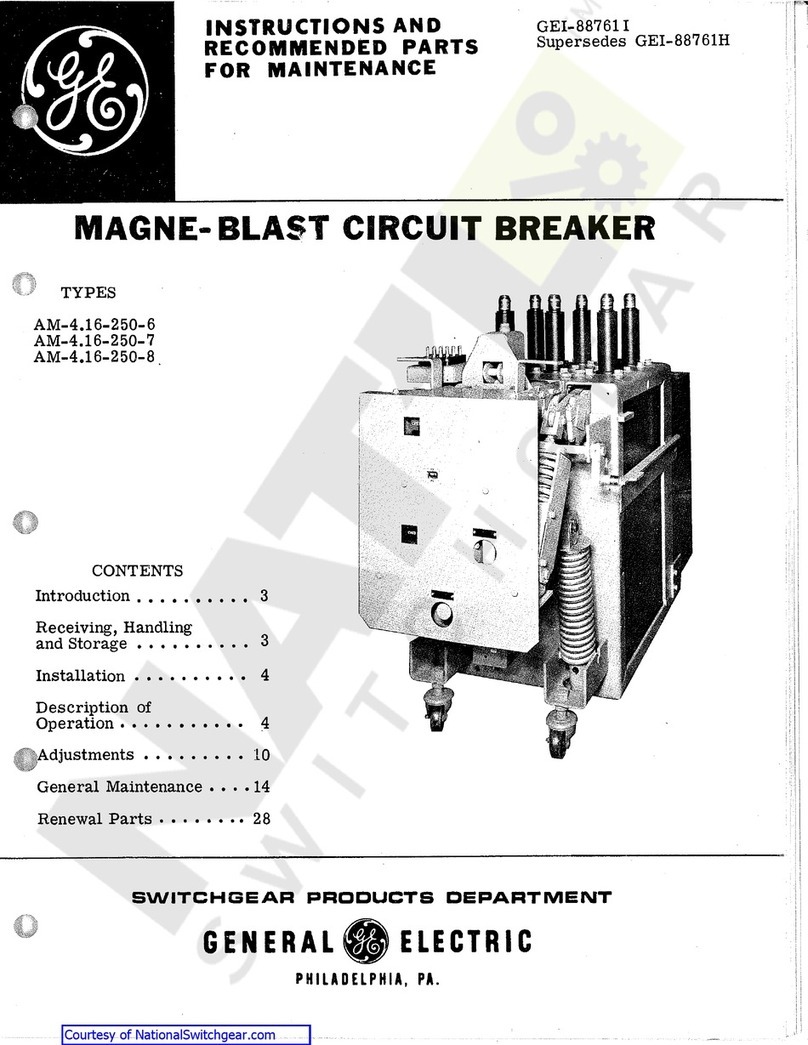
GE AM-4.16-250-6 User manual
GE
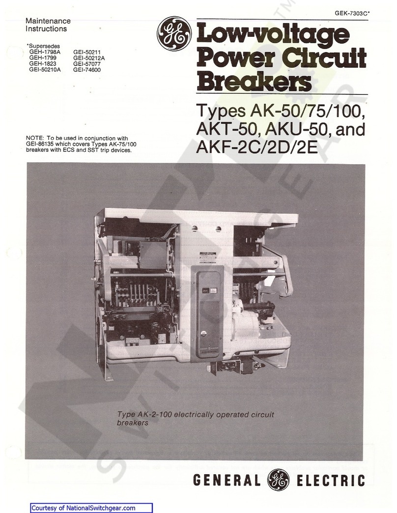
GE AK-50 Series Technical specifications

GE
GE ReliaGear Pro-Stock THQB User manual

GE
GE MicroVersaTripPlus AK-50 User manual

GE
GE MicroVersaTrip AKR-75 User manual

GE
GE Power Break II User manual

GE
GE AK-4-75 User manual

GE
GE MicroVersa Trip Plus User manual

GE
GE SD200SA User manual

GE
GE AM-4.16-250-9 User manual

GE
GE PVDB-28kV User manual

GE
GE WavePro LVPCB User guide

GE
GE Rapid TripFix User manual

GE
GE Pro-Stock SF250 User manual