ADC ES35/35 User manual

2 American Dryer Corp. 450319- 1
Retain This Manual in a Safe Place for Future Reference
This product embodies advanced concepts in engineering, design, and safety. If this product is properly
maintained, it will provide many years of safe, efficient, and trouble free operation.
Only qualified technicians should service this equipment.
OBSERVE ALL SAFETY PRECAUTIONS displayed on the equipment or specified in the installation
manual included with the dryer.
The following “FOR YOUR SAFETY” caution must be posted near the dryer in a prominent location.
FOR YOUR SAFETY
Do not store or use gasoline
or other flammable vapors
and liquids in the vicinity of
this or any other appliance.
POUR VOTRE SÉCURITÉ
Ne pas entreposer ni utiliser d’essence
ni d’autres vapeurs ou liquides
inflammables à proximité de cet
appareil ou de tout autre appareil.
“IMPORTANT NOTE TO PURCHASER”
Information must be obtained from your local gas supplier on the
instructions to be followed if the user smells gas. These
instructions must be posted in a prominent location near the dryer.
We have tried to make this manual as complete as possible and hope you will find it useful. The manufacturer
reserves the right to make changes from time to time, without notice or obligation, in prices, specifications,
colors, and material, and to change or discontinue models. The illustrations included in this manual may
not depict your particular dryer exactly.
IMPORTANT
For your convenience, log the following information:
DATE OF PURCHASE ________________________________________________________ MODEL NO. ______________
RESELLER’S NAME __________________________________________________________________________________
SERIAL NUM ER(S) __________________________________________________________________________________
____________________________________________________________________________________________________
____________________________________________________________________________________________________
Replacement parts can be obtained from your reseller or the ADC factory. When ordering replacement parts
from the factory, you can FAX your order to ADC at +1 508) 678-9447 or telephone your order directly to the
ADC Parts Department at +1 508) 678-9000 or contact parts@amdry.com. Please specify the dryer model
number and serial number in addition to the description and part number, so that your order is processed
accurately and promptly.
ES35/35

450319- 1 www.amdry.com 3
Table of Contents _______________
List of Acronyms ______________________
L.P. Liquid Propane
OSHA Occupational Safety and Health Administration
T.E.F.C. Totally Enclosed, Fan-Cooled
IMPORTANT
You must disconnect and lockout the electric
supply and the gas supply or the steam supply
before any covers or guards are removed from
the machine to allow access for cleaning,
adjusting, installation, or testing of any
equipment per OSHA standards.
Please observe all safety precautions displayed
on the equipment and specified in the
installation manual included with the dryer.
FOR YOUR SAFETY
Do not store or use gasoline or other flammable
vapors and liquids in the vicinity of this or any
other appliance.
Do not dry mop heads in the dryer.
Do not use dryer in the presence of dry cleaning
fumes.
CAUTION
Dryers should never be left unattended while
in operation.
“Caution: Label all wires prior to disconnection
when servicing controls. Wiring errors can
cause improper operation.”
«Attention: Au moment de l’entretien des
commandes, étiquetez tous les fils avant de les
débrancher. Des erreurs de câblage peuvent
entraîner un fonctionnement inadéquat et
dangereux.»
WARNING
Children should not be allowed to play on or
near the dryers.
Children should be supervised if near dryer s)
in operation.
The dryer must never be operated with any of
the back guards, outer tops, or service panels
removed. Personal injury or fire could result.
The dryer must never be operated without the
lint filter or screen in place, even if an external
lint collection system is used.
The wiring diagram for the dryer is located in
the front electrical control box area.
Important Information ................................. 4
A. Safety Precautions ..................................................... 4
Routine Maintenance................................... 6
A. Cleaning ...................................................................... 6
B. Adjustments ................................................................ 7
Installation Requirements........................... 8
A. Enclosure, Air Supply, and Exhaust Requirements ... 8
B. Electrical and Gas Requirements .............................. 8
C. Operational Service Check Procedure ...................... 9
Description of Parts .................................. 10
A. Control Panel Microprocessor) ............................... 10
B. Globar ....................................................................... 10
C. Gas Burner Assembly ............................................... 10
D. Drive Motor ............................................................... 11
E. Motorized Impellor Blower Motor) ........................... 11
F. Tumbler ..................................................................... 11
G. Main Door Switch ...................................................... 12
H. Sail Switch ................................................................ 12
I. Burner Thermostat .................................................... 12
J. Exhaust Hi-limit Thermostat ..................................... 13
K. Lint Drawer ............................................................... 13
L. Lint Drawer Switch .................................................... 13
M. Reversing Relay ....................................................... 13
Servicing.................................................... 14
Introduction .................................................................... 14
A. Computer Controls ................................................... 14
B. Glo-Bar Controls ....................................................... 16
C. Thermostats .............................................................. 19
D. Sail Switch Assembly ............................................... 19
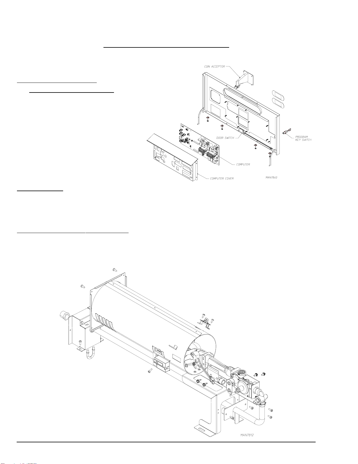
E. Front Panel and Main Door Assemblies .................. 20
F. To Replace Lint Drawer Switch ................................ 25
Faults ......................................................... 29
Events ........................................................ 30
Technical Information ............................... 31
A. Data Label ................................................................ 31
B. Using A Manometer .................................................. 32

4 American Dryer Corp. 450319- 1
SECTION I
IMPORTANT INFORMATION
A. SAFETY PRECAUTIONS
WARNING: For your safety, the information in this manual must be followed to minimize the risk of
fire or explosion or to prevent property damage, personal injury, or loss of life.
The dryer must never be operated with any of the back guards, outer tops, or
service panels removed. PERSONAL INJURY OR FIRE COULD RESULT.
1. Do not store or use gasoline or other flammable vapors and liquids in the vicinity of this or any other appliance.
2. Purchaser/user should consult the local gas supplier for proper instructions to be followed in the event the user
smells gas. The instructions should be posted in a prominent location.
3. WHAT TO DO IF YOU SMELL GAS...
a. Do not try to light any appliance.
b. Do not touch any electrical switch.
c. Do not use any phone in your building.
d. Clear the room, building, or area of all occupants.
e. Immediately call your gas supplier from a neighbor’s phone. Follow the gas supplier’s instructions.
f. If you cannot reach your gas supplier, call the fire department.
4. Installation and service must be performed by a qualified installer, service agency, or gas supplier.
5. Dryer s) must be exhausted to the outdoors.
6. Although ADC produces a very versatile dryer, there are some articles that, due to fabric composition or cleaning
method, should not be dried in it.
WARNING: Dry only water washed fabrics. Do not dry articles spotted or washed in dry cleaning
solvents, a combustible detergent, or “all purpose” cleaner. EXPLOSION COULD
RESULT.
Do not dry rags or articles coated or contaminated with gasoline, kerosene, oil, paint, or
wax. EXPLOSION COULD RESULT.
Do not dry mop heads. Contamination by wax or flammable solvents will create a fire
hazard.
Do not use heat for drying articles that contain plastic, foam, sponge rubber, or similarly
textured rubber materials. Drying in a heated tumbler may damage plastics or rubber
and may be a fire hazard.
7. A program should be established for the inspection and cleaning of lint in the heating unit area, exhaust ductwork,
and inside the dryer. The frequency of inspection and cleaning can best be determined from experience at each
location.
WARNING: The collection of lint in the burner area and exhaust ductwork can create a potential fire
hazard.
8. For personal safety, the dryer must be electrically grounded in accordance with local codes and/or the National
Electrical Code ANSI/NFPA NO. 70-LATEST EDITION or in Canada, the Canadian Electrical Codes Parts 1 & 2
CSA C22.1-1990 or LATEST EDITION.

450319- 1 www.amdry.com 5
NOTE: Failure to do so will void the warranty.
9. Under no circumstances should the dryer door switches, lint door switch, heat safety circuit ever be disabled.
WARNING: PERSONAL INJURY OR FIRE COULD RESULT.
10. This dryer is not to be used in the presence of dry cleaning solvents or fumes.
11. Remove articles from the dryer as soon as the drying cycle has been completed.
WARNING: Articles left in the dryer after the drying and cooling cycles have been completed can
create a fire hazard.
12. Do not operate steam dryers with more than 125 PSI 8.61 bars) steam pressure. Excessive steam pressure
can damage steam coil and/or harm personnel.
13. Replace leaking flexible hoses or other steam fixtures immediately. Do not operate the dryer with leaking
flexible hoses. PERSONAL INJURY MAY RESULT.
14. READ AND FOLLOW ALL CAUTION AND DIRECTION LA ELS ATTACHED TO THE DRYER.
WARNING: YOU MUST DISCONNECT AND LOCKOUT THE ELECTRIC SUPPLY AND THE GAS
SUPPLY OR THE STEAM SUPPLY EFORE ANY COVERS OR GUARDS ARE
REMOVED FROM THE MACHINE TO ALLOW ACCESS FOR CLEANING,
ADJUSTING, INSTALLATION, OR TESTING OF ANY EQUIPMENT PER OSHA
STANDARDS.

6 American Dryer Corp. 450319- 1
SECTION II
ROUTINE MAINTENANCE
A. CLEANING
A program or schedule should be established for periodic inspection, cleaning, and removal of lint from various areas
of the dryer, as well as throughout the ductwork system. The frequency of cleaning can best be determined from
experience at each location. Maximum operating efficiency is dependent upon proper air circulation. The accumulation
of lint can restrict this airflow. If the guidelines in this section are met, an ADC dryer will provide many years of
efficient, trouble free, and most importantly, safe operation.
WARNING: LINT FROM MOST FA RICS IS HIGHLY COM USTI LE. THE ACCUMULATION OF
LINT CAN CREATE A POTENTIAL FIRE HAZARD.
KEEP DRYER AREA CLEAR AND FREE FROM COM USTI LE MATERIALS,
GASOLINE, AND OTHER FLAMMA LE VAPORS AND LIQUIDS.
NOTE: Suggested time intervals shown are for average usage which is considered six to eight
operational running) hours per day.
Clean lint drawer and screen every third or fourth load.
NOTE: Frequency can best be determined at each location.
DAILY
Beginning of each work shift.
Clean lint from the drawer and screen. Inspect lint screen and replace if torn.
WEEKLY
Clean lint accumulation from lint chamber, thermostat, and microprocessor temperature sensor area.
WARNING: To avoid the hazard of electrical shock, discontinue electrical supply to the dryer.
STEAM DRYERS
Clean steam coil fins using compressed air and a vacuum cleaner with brush attachment.
NOTE: When cleaning steam coil fins, be careful not to bend the fins. If the fins are bent,
straighten by using a fin comb, which is available from local air conditioning supply houses.
90 DAYS
Remove lint from tumbler, drive motors, and surrounding areas. Remove lint from gas valve burner area with a
dusting brush or vacuum cleaner attachment.
NOTE: To prevent damage, avoid cleaning and/or touching the ignitor/globar probe assembly.

450319- 1 www.amdry.com 7
6 MONTHS
Inspect and remove lint accumulation in customer furnished exhaust ductwork system and from dryer’s internal
exhaust ducting.
NOTE: THE ACCUMULATION OF LINT IN THE EXHAUST DUCTWORK CAN CREATE A
POTENTIAL FIRE HAZARD.
DO NOT OBSTRUCT THE FLOW OF COMBUSTION AND VENTILATION AIR. CHECK
CUSTOMER FURNISHED BACK DRAFT DAMPERS IN THE EXHAUST DUCTWORK.
INSPECT AND REMOVE ANY LINT ACCUMULATION, WHICH CAN CAUSE THE
DAMPER TO BIND OR STICK.
A back draft damper that is sticking partially closed can result in slow drying and shutdown
of heat circuit safety switches or thermostats.
When cleaning the dryer cabinet s), avoid using harsh abrasives. A product intended for
the cleaning of appliances is recommended.
B. ADJUSTMENTS
7 DAYS AFTER INSTALLATION AND EVERY 6 MONTHS THEREAFTER
Inspect bolts, nuts, screws, grounding connections, and nonpermanent gas connections unions, shutoff valves, and
orifices). Motor and drive belts should be examined. Cracked or seriously frayed belts should be replaced. Complete
operational check of controls and valves. Complete operational check of all safety devices door switches, lint
drawer switch, sail switch, burner and hi-limit thermostats).

8 American Dryer Corp. 450319- 1
SECTION III
INSTALLATION REQUIREMENTS
Installation should be performed by competent technicians in accordance with local and state codes. In the absence
of these codes, the installation must conform to applicable American National Standards: ANSI Z223.1-LATEST
EDITION National Fuel Gas Code) or ANSI/NFPA NO. 70-LATEST EDITION National Electrical Code) or in Canada,
the installation must conform to applicable Canadian Standards: CAN/CGA-B149.1-M91 Natural Gas) or CAN/CGA-
B149.2-M91 L.P. Gas) or LATEST EDITION for General Installation and Gas Plumbing) or Canadian Electrical
Codes Parts 1 & 2 CSA C22.1-1990 or LATEST EDITION for Electrical Connections).
A. ENCLOSURE, AIR SUPPLY, AND EXHAUST REQUIREMENTS
NOTE: The following information is very brief and general. For a detailed description, refer to the
Installation Manual supplied with the dryer.
Bulkheads and partitions around the dryer should be made of noncombustible materials. Allowances should be
made for the opening and closing of the control door and lint drawer. Also, allowances should be made in the rear for
ease of maintenance. Refer to the appropriate Installation Manual for recommended distances and minimum
allowances required.)
When the dryer is operating, it draws in room air, heats it, passes this air through the tumbler, and exhausts it out of
the building. Therefore, the room air must be continually replenished from the outdoors. If the make-up air is
inadequate, drying time and drying efficiency will be adversely affected. Ignition problems and sail switch “fluttering”
problems on gas dryers may result, and you also could have premature motor failure from overheating. The air
supply must be given careful consideration to insure proper performance of each dryer.
IMPORTANT: Make-up air must be provided from a source free of dry cleaning fumes. Make-up air
that is contaminated by dry cleaning fumes will result in irreparable damage to the
motors and other dryer components.
Exhaust ductwork should be designed and installed by a competent technician. Improperly sized ductwork will create
excessive back pressure, which will result in slow drying, increased use of energy, and shutdown of the burner by the
airflow sail) switch, burner hi-limit or lint chamber hi-heat protector thermostat. Refer to the appropriate Installation
Manual for more details.)
CAUTION: IMPROPERLY SIZED OR INSTALLED EXHAUST DUCTWORK CAN CREATE A
POTENTIAL FIRE HAZARD.
B. ELECTRICAL AND GAS REQUIREMENTS
It is your responsibility to have all electrical connections made by a properly licensed and competent electrician to
assure that the electrical installation is adequate and conforms to local and state regulations or codes. In the absence
of such codes, all electrical connections, materials, and workmanship must conform to the applicable requirements
of the National Electrical Code ANSI/NFPA NO. 70-LATEST EDITION or in Canada, the Canadian Electrical Codes
Parts 1 & 2 CSA C22.1-1990 or LATEST EDITION.
IMPORTANT: Failure to comply with these codes or ordinances and/or the requirements stipulated
in this manual can result in personal injury or component failure.

450319- 1 www.amdry.com 9
The gas dryer installation must meet the American National Standard...National Fuel Gas Code ANSI Z223.1-LATEST
EDITION, or in Canada, the Canadian Installation Codes CAN/CGA-B149.1 M91 Natural Gas) or CAN/CGA-B149.2-
M91 L.P. Gas) or LATEST EDITION, as well as local codes and ordinances and must be done by a qualified
professional.
NOTE: Undersized gas piping will result in ignition problems, slow drying, and can create a safety
hazard.
The dryer must be connected to the type of gas natural or L.P.) indicated on the dryer data label. If this information
does not agree with the type of gas available, contact the reseller who sold the dryer or contact the factory.
The gas input ratings shown on the dryer data label are for elevations up to 2,000 feet 609.6 meters), unless
elevation requirements of over 2,000 feet 609.6 meters) were specified at the time the dryer order was placed with
the factory. The adjustment for dryers in the field for elevations over 2,000 feet 609.6 meters) is made by changing
the burner orifices. If this adjustment is necessary, contact the reseller who sold the dryer or contact the factory.
NOTE: Any burner changes must be made by a qualified technician.
C. OPERATIONAL SERVICE CHECK PROCEDURE
1. Turn on electric power to the dryer.
2. To start dryer:
a. Display will read “Select Cycle.”
b. Select a cycle using the keypad of the microprocessor controller computer).
c. The dryer will start, and the display will show cycle type and minutes remaining.
3. Make a complete operational check of all the operating controls to assure that the timing is correct, temperature
selection switches are functioning, etc.
4. Make a complete operational check of all safety-related circuits: door switch es), hi-limit thermostat, sail switch,
cycling thermostats, etc.
5. For gas dryers a gas pressure test should be taken at the gave valve pressure tap of each dryer to assure that
the water column pressure is correct and consistent.
NOTE: Water column pressure requirements measured at the pressure tap on the gas valve
body):
Natural Gas ________________ 3.0 Inches 6.9 mb) Water Column.
L.P. Gas ___________________ 10.5 Inches 26.1 mb) Water Column.
6. If computer program changes are required, refer to the Phase 8 Non-Coin Operator’s Manual ADC P/N 113604)
for details.
7. The dryer should be operated through one complete cycle to assure that no further adjustments are necessary
and that all components are functioning properly.

10 American Dryer Corp. 450319- 1
SECTION IV
DESCRIPTION OF PARTS
A. CONTROL PANEL
MICROPROCESSOR)
Lifting the control door will reveal the control
panel assembly. Opening the control panel
will allow access to the major components
which include the computer board and
keypad. The keypad inputs to the computer
what temperature and program has been
selected. The computer controls the entire
operation of the dryer. It accepts inputs and
gives outputs to various parts throughout
the dryer.
B. GLOBAR
The globar is a 120 VAC device. When the Globar meets its peak radiant heat the I-R sensor “infrared sensor”
senses the heat and powers the gas valve.
C. GAS BURNER ASSEMBLY
Gas heated dryers are equipped with a gas burner assembly consisting of one burner tube, one gas valve, Glo-Bar
and infrared sensor. The inlet piping enters through the rear of the dryer on the right-hand side viewing from the
front) and runs to the front of the dryer where the gas valve is located.

450319- 1 www.amdry.com 11
D. DRIVE MOTOR
The drive motor is located in the left side of the
machine viewing from the front) of the dryer. It sits
on an adjustable base so that the motor can be
easily adjusted for belt tension adjustment. The
drive motor is a 1/4 HP motor and operates on 115
to 230 volts, 50/60 Hz.
E. MOTORIZED IMPELLOR
BLOWER MOTOR)
Viewing from the front of the dryer.) The blower motor is
in the center of the dryer in the front. The motorized
impellor is a backward curved fan, which sits in a sealed
box below the basket.
F. TUMBLER
The tumbler has three ribs, a front felt, and a back felt, which are used to seal the tumbler to the front and rear wall of
the dryer.

12 American Dryer Corp. 450319- 1
G. MAIN DOOR SWITCH
The main door switch is located in the main control panel. When the main door opens, the switch will also open,
preventing the dryer from operating. The main door switch is a safety device and should never be disabled.
H. SAIL SWITCH
The sail switch is located on the rear of the machine. A sail switch consists of a round damper plate on a lever arm
which is in contact with an electric switch. When the air blower comes on, it draws air through the gas burner. This
creates a negative pressure inside the burner box, and this negative pressure pulls in the round damper and activates
the sail switch. If there is improper airflow, the damper will not pull in, preventing the burner from starting.
Improper airflow can be caused by improperly designed exhaust ducting where the duct run is too long or has too
many sharp bends in it. It can also be caused by a lack of make-up air.
I. BURNER THERMOSTAT
A hi-limit thermostat is located at the top of the heat duct. This is an automatic reset disc-type thermostat set at 205°
F 96.11° C). If the flame in the burner should get too hot, this thermostat will shut off the burner. This is generally
caused by low airflow through the dryer.

450319- 1 www.amdry.com 13
J. EXHAUST HI-LIMIT THERMOSTAT
This is a 190º automatic thermostat located in the lint compartment above the lint drawer. This thermostat senses the
heated air after it has passed through the tumbler. If the air temperature gets too hot, the thermostat will shut off the
burner. The dryer will not run until the air temperature cools down. At this time, the thermostat will reset. Tumbler
and blower will run, but dryer will not heat.
K. LINT DRAWER
The lint drawer is a pullout type and is located at the bottom of the dryer in the lint compartment. Simply grab the lint
drawer handle, slide out the drawer, brush off the lint, and slide the drawer back in. The lint screen must be kept
clean in order for the dryer to operate properly and efficiently.
L. LINT DRAWER SWITCH
The lint drawer switch is located in the rear of the lint compartment and attached to the back of the lint drawer
compartment. The lint drawer switch insures that the dryer will operate only when the lint drawer is completely
closed. This is a safety device and should never be disabled.
M. REVERSING RELAY
The reversing relay is located directly in front of the drive motor.

14 American Dryer Corp. 450319- 1
SECTION V
SERVICING
INTRODUCTION
All electrical/mechanical service or repairs should be made with the electrical power to the dryer disconnected power
off).
WARNING: PERSONAL INJURY COULD RESULT.
The information provided in this section should not be misconstrued as a device for use by an untrained person
making repairs. Service work should be performed by competent technicians in accordance with local, state, and
federal codes.
When contacting the factory for assistance, always have the dryer model and serial numbers available.
CAUTION: Observe all safety precautions displayed on the dryer or specified in this manual before
and while making repairs.
Before considering replacement, make sure that all connectors are in place and making proper contact.
A. COMPUTER CONTROLS
To Replace Computer
1. Discontinue electrical power to the dryer.
2. See instructions for “removing control and lint door/toe panel”.
3. Disconnect main power harness from rear of computer by squeezing locking tab and pulling all other connectors
from rear of computer board.
4. Disconnect the green ground wire from the computer panel.
5. Disconnect keypad ribbon from the computer.
6. Remove the four hex nuts securing the computer cover to the control panel. Remove the eight Phillips pan head
screws, pull back on computer board to remove.
7. Install new computer by reversing this procedure.
8. When replacing the computer, the computer must be programmed. Please refer to the Computer Operator’s
Manual for details.)
9. Reestablish electrical power to the dryer.
Removing Control Door and Lint Door / Toe Panel
1. Discontinue power to unit.
2. Open loading door to find four Torx screws located at the top of each panel. The control panel will also have
screws at the bottom edge, which must be removed.
3. Hinge panel down from the top then lift up to remove. Control panel wiring will need to be removed before panel
can be taken off machine.
4. Reinstall panels by reversing this procedure.

450319- 1 www.amdry.com 15
To Replace Keypad Label Assembly
1. Discontinue electrical power to the dryer.
2. Repeat step 1-5 for computer board removal.
3. Slowly peel off and remove keypad label assembly from
control panel.
4. Peel paper backing off new keypad label assembly.
5. Holding the new keypad label assembly close to the
panel, insert the keypad ribbon through the rectangular
slot in the control panel. Align label assembly into
position by matching the clear viewing window on the
label to the rectangular cutout in the panel and gently
press into place.
6. Reverse the above procedure.
7. Reestablish electrical power to the dryer.
To Replace Microprocessor Exhaust Temperature Sensor Probe
1. Discontinue electrical power to the dryer.
2. Loosen the 5/16 Pal nut securing sensor bracket assembly to the dryer.
3. Disconnect sensor bracket harness connector.
4. Install new sensor probe assembly by reversing procedure.
5. Reestablish electrical power to the dryer.
NOTE: If, when power is reestablished, the computer display reads exhaust probe fault check for a
loose connection in the wiring.

16 American Dryer Corp. 450319- 1
B. GLO-BAR CONTROLS
To Replace Globar
1. Discontinue electrical power to the dryer.
2. Disconnect Glo-Bar connector.
3. Disassemble ignitor from burner by removing the single ignitor mounting screw.
4. Reverse procedure for installing new Glo-Bar ignitor.
To Replace Gas Valve
1. Discontinue electrical power to the dryer.
2. Close shutoff valve s) in gas supply line.
3. Disconnect gas valve wiring.
4. Break union connection before gas valve.
5. Loosen and remove the two T-20 Torx screws securing pipe brackets to burner.
6. Remove gas valve/manifold assembly from dryer.
7. Remove valve mounting bracket, manifold, and piping from gas valve.
8. Reverse procedure for installing new gas valve.
WARNING: Test all connections for leaks by brushing on a soapy water solution. NEVER TEST
FOR LEAKS WITH A FLAME.

450319- 1 www.amdry.com 17
To Replace Main Burner Orifices
1. Refer to “To Replace Gas Valve” and follow steps 1 through 6.
2. Unscrew main burner orifices and replace.
NOTE: Use extreme care when removing and replacing orifices. These orifices are made of brass
and are easily damaged.
3. Reverse the removal procedure for reinstallation.
NOTE: Test all connections for leaks by brushing on a soapy water solution. NEVER TEST FOR
LEAKS WITH A FLAME.
To Test and Adjust Gas Water Column) Pressure
There are two types of devices commonly used to measure water column pressure. They are spring/mechanical-
type gauges and manometers. The spring/mechanical-type gauge is not recommended, because it is easily damaged
and not always accurate. A manometer is simply a glass or transparent plastic tube with a scale in inches. When
filled with water and pressure applied, the water in the tube rises showing the exact water column pressure.
NOTE: Manometers are available from the factory by ordering ADC P/N 122804.
1. To test gas water column pressure:
a. Connect water column test gauge connection to
gas valve pressure tap 1/8” N.P.T.). This pressure
tap is located on the outlet manifold) side of the
valve.
b. Start dryer. With burner on, the correct water
column reading in inches would be:
Natural Gas – 3.0 inches 6.9 mb) water column.
L.P. Gas – 10.5 inches 26.1 mb) water column.
2. To adjust water column pressure natural gas only, L.P.
gas must be regulated at source):
a. Remove the brass vent cap on the top of the valve.
b. Turn the slotted adjustment screw located under
the brass vent cap at the top of the valve. Turn
clockwise to increase manifold pressure and
counterclockwise to decrease.
NOTE: If correct water column pressure cannot
be achieved, problem may be due to an
undersized gas supply line, a faulty or
underrated gas meter, etc.

18 American Dryer Corp. 450319- 1
L.P. Gas Conversion Instructions
Disconnect electrical power to the dryer.
Close all shutoff valves for both top and bottom tumbler) in dryer’s gas supply line.
IMPORTANT: The following procedures must be performed on both top and bottom tumblers.
Open the panels located just below each loading door.
Locate the gas train and disconnect the union, three electrical plugs, and the gas train mounting screws from the
burner. Carefully slide the gas train out of the gas train enclosure. The carbon ignitor located at the far end of the
gas train is very fragile.)
Remove two burner tube mounting screws and remove burner tube in order to gain access to the orifice.
Using a 3/8” wrench or socket, remove the existing orifice and replace it with an orifice from the kit.
IMPORTANT: Use extreme care when removing and replacing orifice injector). This orifice injector) is made of
brass, which is easily damaged.
Reinstall the burner tube onto the burner base.
Use a flat screwdriver to remove the regulator vent cap.
•For unregulated L.P. gas (most countries): install blocking pin ADC P/N 140414).
Install the gas train back into the dryer gas train enclosure. Be sure the tab at the rear of the gas train engages into
the mounting slot.
Connect the union and the three electrical plugs.
Repeat these steps for the other burner.
Affix L.P. Conversion Label ADC P/N 114515) to the dryer’s data label.
Complete L.P. Kit Conversion Confirmation Label ADC P/N 114083) and affix this label as close as possible to the
dryer’s existing dryer rating data) label/plate.
Regulate govern) gas externally refer to “To Test and Adjust Gas Pressure” in chart on page 17) to the correct gas
pressure for the gas being used. Operate dryer through one complete cycle to ensure proper operation.
Affix L.P. Conversion Rating Label Addendum ADC P/N 114090) as close as possible to the dryer’s existing dryer
rating data) label/plate.
IMPORTANT: Never test for leaks with an open flame!!! Use a soapy water solution or product intended for that
purpose.

450319- 1 www.amdry.com 19
D. SAIL SWITCH ASSEMBLY
The sail switch is a heat circuit safety device which controls the burner circuit only. When the dryer is operating and
there is proper airflow, the sail switch damper pulls in and closes the sail switch. Providing all the other heat-related
circuits are functioning properly, ignition should now be established. If an improper airflow occurs, the sail switch
damper will release, and the circuit will open.
To Replace Lint Compartment / Exhaust Hi-Limit 190° F [87° C]) Thermostat
This thermostat is part of the “lint box assembly” and is secured
to the top lint box beneath tumbler. As a safety device, this
thermostat will open shut off) the heating unit circuit if an
excessive temperature occurs. The dryer motors will remain on,
even if the thermostat is open.
IMPORTANT: Under no circumstances should heat
safety devices be disabled.
1. Discontinue electrical power to the dryer.
2. Remove control or lint panel.
3. Locate exhaust hi-limit at front left side of lint box. Remove
wires from thermostat and remove the two 11/32” Hex nuts.
4. Reverse this procedure for installing a hi-limit thermostat.
5. Reestablish electrical power to the dryer.
C. THERMOSTATS
To Replace Burner Hi-Limit Thermostat
This thermostat is an important safety device serving as an added protection against failure of the airflow sail switch)
to open in the event of motor failure or reduced airflow condition.
IMPORTANT: Under no circumstances should heat circuit safety devices ever be disabled.
1. Discontinue electrical power to the dryer.
2. Remove large back guard.
3. Disconnect wires from hi-limit thermostat.
4. Remove screws securing thermostat
to the heat duct. Remove thermostat.
5. Reverse procedure for installing new
thermostat.
6. Reestablish electrical power to the
dryer.

20 American Dryer Corp. 450319- 1
E. FRONT PANEL AND MAIN DOOR ASSEMBLIES
To Replace Main Door Switch
1. Discontinue electrical power to the dryer.
2. Open main door.
3. Remove the Phillips head screws holding the top or main
control panel.
4. Disconnect wiring connecting switch to computer board/
harness.
5. Disassemble door switch from bracket by removing two
Phillips screws securing the switch to the panel.
6. Reverse this procedure for installing new door switch.
7. Reestablish electrical power to the dryer.
IMPORTANT: Under no circumstances should the
door switch be disabled.
To Install New Main Door Glass
1. Remove main door assembly from dryer.
2. Lay main door on flat surface with the rear of the door facing up.
3. Drill all outer permiter pop rivets and remove door handle.
4. Remove glass and clean all old sealant off main door. This area must be completely cleaned for correct bonding.
5. Apply a narrow bead of silicone ADC P/N 170730) all around main door area where glass will rest.
6. Install glass onto door adhesive and slightly press glass in place.
IMPORTANT: Do not press hard or silicone thickness between the glass and door, the bead of
silicone will be reduced, resulting in poor bonding.
7. The door assembly should now be put in an area where it will not be disturbed for at least 24 hours. Depending
on the conditions, the curing time of this adhesive is 24 to 36 hours.
8. Pop rivet the inner door to the outer door and reattach the door handle.
9. After 24-hour curing period, install main door on dryer by reversing Step #1-2.
Table of contents
Other ADC Dryer manuals