ADC AD-170SE User manual

AD-170SE Installation Manual
Phase 7 / Non-Coin / S.A.F.E. System
ADC Part No. 113398-12
American Dryer Corporation
88CurrantRoad
FallRiverMA02720-4781USA
Telephone:+1(508) 678-9000 /Fax:+1 (508)678-9447
e-mail:techsupport@amdry.com
www.amdry.com
WARNING:Foryoursafetytheinformation
in this manual must be followed to
minimize the risk of fire or explosion and
to prevent property damage, personal
injuryordeath.
— Do not store or use gasoline or other
flammable vapors and liquids in the
vicinityof thisor anyother appliance.
— WHATTODOIFYOU SMELLGAS:
●Donot tryto lightany appliance.
●Donot touchanyelectricalswitch;
donot useanyphoneinyour
building.
●Cleartheroom, building orareaof
alloccupants.
●Immediatelycall yourgassupplier
fromaneighbor’sphone. Follow
thegas supplier’sinstructions.
●Ifyoucannotreachyourgas
supplier,callthefiredepartment.
— Installation and service must be
performedbyaqualifiedinstaller,service
agencyor thegassupplier.
AVERTISSEMENT:Assurez-vousdebien
suivrelesinstructionsdonnéesdanscette
noticepour réduireau minimumle risque
d’incendie ou d’explosion ou pour éviter
toutdommagematériel,touteblessureou
lamort.
—Ne pas entreposer ni utiliser d’essence
nid’autres vapeursouliquides
inflammablesàproximité decet
appareiloude toutautre appareil.
—QUEFAIRE SIVOUS SENTEZUNE
ODEURDEGAZ:
●Nepastenter d’allumerd’appareils.
●Netouchezàaucuninterrupteur. Ne
pasvousservirdestéléphones se
trouvantdanslebâtiment.
●Évacuezlapièce,lebâtiment oula
zone.
●Appelezimmédiatement votre
fournisseurde gazdepuis unvoisin.
Suivezlesinstructionsdufournisseur.
●Sivous nepouvez rejoindrele
fournisseurde gaz,appelez leservice
desincendies.
—L’installation et l’entretien doivent être
assurés par un installateur ou un
service d’entretien qualifié ou par le
fournisseurde gaz.

Retain This Manual In ASafe Place For Future Reference
American Dryer Corporation products embody advanced concepts in engineering, design, and safety. If this product is
properly maintained, it will provide many years of safe, efficient, and trouble free operation.
ONLY qualified technicians should service this equipment.
OBSERVE ALL SAFETY PRECAUTIONS displayed on the equipment or specified in the installation manual included with
the dryer.
The following “FOR YOUR SAFETY” caution must be posted near the dryer in a prominent location.
“IMPORTANTNOTETOPURCHASER”
Informationmustbeobtainedfromyourlocalgassupplierontheinstructions
tobe followedifthe usersmells gas. Theseinstructions mustbepostedin a
prominentlocationnearthedryer.
We have tried to make this manual as complete as possible and hope you will find it useful. ADC reserves the right to make
changes from time to time, without notice or obligation, in prices, specifications, colors, and material, and to change or
discontinue models. The illustrations included in this manual may not depict your particular dryer exactly.
Important
For your convenience, log the following information:
DATE OFPURCHASE__________________________________________________ MODEL NO. ________________________
RESELLER’SNAME ________________________________________________________________________________________
Serial Number(s) ________________________________________________________________________________________
________________________________________________________________________________________
________________________________________________________________________________________
Replacement parts can be obtained from your reseller or the ADCfactory. When orderingreplacement parts fromthe factory,
you canFAX your order to ADCat +1(508) 678-9447or telephoneyourorderdirectlytotheADC Parts Departmentat +1(508)
678-9000. Pleasespecify the dryermodelnumberand serialnumberin addition tothe descriptionand partnumber, sothat
your order is processed accurately and promptly.
AD-170 PH7
FOR YOUR SAFETY
Do not store or use gasoline
orother flammablevapors
andliquids inthevicinityof
thisor anyother appliance.
POUR VOTRE SÉCURITÉ
Ne pas entreposer ni utiliser d’essence
nid’autres vapeursouliquides
inflammablesàproximité decet
appareiloude toutautre appareil.

IMPORTANT
YOUMUSTDISCONNECTANDLOCKOUTTHEELECTRICSUPPLYANDTHEGAS
SUPPLY OR THE STEAM SUPPLY BEFORE ANY COVERS OR GUARDS ARE
REMOVED FROM THE MACHINE TO ALLOW ACCESS FOR CLEANING,
ADJUSTING, INSTALLATION, OR TESTING OFANY EQUIPMENT PER OSHA
(OccupationalSafetyandHealthAdministration) STANDARDS.
WARNING
CHILDRENSHOULD NOTBEALLOWEDTOPLAYONORNEARTHEDRYER(S).
CHILDRENSHOULDBESUPERVISEDIFNEARDRYERSINOPERATION.
CAUTION
DRYERSSHOULDNEVERBELEFTUNATTENDEDWHILEINOPERATION.
FORYOURSAFETY
DONOTDRYMOPHEADSINTHEDRYER.
DONOTUSEDRYER INTHEPRESENCEOFDRYCLEANINGFUMES.
WARNING
UNDERNO CIRCUMSTANCESshouldthedryerdoorswitches, thelintdrawerswitch,
or the heat circuit ever be disabled.
“Caution:Label allwires priorto
disconnection when servicing
controls.Wiringerrors can cause
improper operation.”
«Attention:Aumomentde l’entretien descommandes,
étiquetez tous les fils avant de les débrancher. Des
erreursdecâblagepeuvententraînerunfonctionnement
inadéquatetdangereux.»
Proposition65
Useof thisproductcould exposeyouto substancesfromfuel combustion
thatcontain chemicalsknowntotheStateof California tocausecancer,
birthdefectsandotherreproductiveharm.
▲ WARNING
!

WARNING
The dryer must never be operated with any of the back guards, outer tops, or service
panelsremoved. PERSONALINJURYORFIRECOULDRESULT.
IMPORTANT
PLEASEOBSERVEALLSAFETYPRECAUTIONSdisplayedontheequipmentand/or
specified in the installation manual included with the dryer.
WARNING
DRYERMUSTNEVERBE OPERATEDWITHOUTTHELINTFILTER/SCREENIN
PLACE,EVENIFANEXTERNALLINTCOLLECTIONSYSTEMISUSED.
Dryer mustnot beinstalled or stored in an area where it willbe exposed to water or weather.
The wiring diagram for the dryer is located in the front electrical control box area.
IMPORTANT
Dryer must be installed in a location/environment, which the ambient temperature
remains between 40° F (4.44° C) and 130° F (54.44° C).

SECTION I
IMPORTANT INFORMATION ...............................................................................3
A. ReceivingandHandling ............................................................................................................... 3
B. SafetyPrecautions ...................................................................................................................... 4
SECTION II
SPECIFICATIONS/COMPONENT IDENTIFICATION..................................... 6
A. Specifications ............................................................................................................................. 6
B. ComponentIdentification ............................................................................................................ 8
SECTION III
INSTALLATION PROCEDURES .........................................................................10
A. LocationRequirements ............................................................................................................. 10
B. Unpacking/SettingUp ............................................................................................................... 11
C. DryerEnclosureRequirements .................................................................................................. 13
D. FreshAirSupplyRequirements ................................................................................................. 14
E. ExhaustRequirements ............................................................................................................... 15
F. ElectricalInformation ................................................................................................................ 21
G. GasInformation ........................................................................................................................ 25
H. SteamInformation .................................................................................................................... 29
I. PreparationforOperation/Start-Up........................................................................................... 33
J. PreoperationalTest ................................................................................................................... 34
K. PreoperationalInstructions ........................................................................................................ 36
L. CompressedAirRequirements .................................................................................................. 36
M. ShutdownInstructions............................................................................................................... 37
SECTION IV
SERVICE/PARTS INFORMATION ......................................................................38
A. Service ..................................................................................................................................... 38
B. Parts ........................................................................................................................................ 38
SECTION V
WARRANTY INFORMATION...............................................................................39
A. ReturningWarranty Cards......................................................................................................... 39
B. Warranty .................................................................................................................................. 39
C. ReturningWarrantyParts .......................................................................................................... 39
Table of Contents

SECTION VI
ROUTINE MAINTENANCE ..................................................................................41
A. Cleaning ................................................................................................................................... 41
B. Adjustments ............................................................................................................................. 43
C. Lubrication ............................................................................................................................... 43
SECTION VII
MANUAL RESET BURNER HI-LIMIT INSTRUCTIONS ...............................44
A. Phase 7 .................................................................................................................................... 44
B. DualTimer................................................................................................................................44
SECTION VIII
DATA LABEL INFORMATION .............................................................................45
SECTION IX
REVERSING TIMER SPIN/DWELL ADJUSTMENTS.....................................46
SECTION X
PROCEDURE FOR FUNCTIONAL CHECK
OF REPLACEMENT COMPONENTS ................................................................47
SECTION XI
SENSOR ACTIVATED FIRE EXTINGUISHING (S.A.F.E.) SYSTEM ...........49

3
SECTION I
IMPORTANT INFORMATION
A. RECEIVING AND HANDLING
The dryer is shipped in a protective stretch wrap cover with protective cardboard corners and top cover (or
optional box) as a means of preventing damage in transit. Upon delivery, the dryer and/or packaging, and
wooden skid should be visually inspected for shipping damage. If any damage whatsoever is noticed, inspect
further before delivering carrier leaves.
Dryers damaged in shipment:
1. ALL dryers should be inspected upon receipt and before they are signed for.
2. If there is suspected damage or actual damage, the trucker’s receipt should be so noted.
3. If the dryer is damaged beyond repair, it should be refused. Those dryers, which were not damaged in a
damaged shipment should be accepted, but the number received and the number refused must be noted
on the receipt.
4. If you determine that the dryer was damaged after the trucker has left your location, you should call the
delivering carrier’s freight terminal immediately and file a claim. The freight company considers this
concealed damage. This type of freight claim is very difficult to get paid and becomes extremely difficult
when more than a day or two passes after the freight was delivered. It is your responsibility to file freight
claims. Dryer/parts damaged in transit cannot be claimed under warranty.
5. Freight claims are the responsibility of the consignee, and ALL claims must be filed at the receiving end.
ADC assumes no responsibility for freight claims or damages.
6. If you need assistance in handling the situation, please contact the ADC Traffic Manager at +1 (508)
678-9000.
IMPORTANT: The dryer must be transported and handled in an upright position at ALL times.

4
B. SAFETY PRECAUTIONS
WARNING: For your safety, the information in this manual must be followed to minimize the risk of
fire or explosion or to prevent property damage, personal injury, or loss of life.
WARNING: The dryer must never be operated with any of the back guards, outer tops, or
service panels removed. PERSONAL INJURY OR FIRE COULD RESULT.
1. DO NOT store or use gasoline or other flammable vapors and liquids in the vicinity of this or any other
appliance.
2. Purchaser/user should consult the local gas supplier for proper instructions to be followed in the event the
user smells gas. The instructions should be posted in a prominent location.
3. WHAT TO DO IF YOU SMELL GAS
a. DO NOT try to light any appliance.
b. DO NOT touch any electrical switch.
c. DO NOT use any phone in your building.
d. Clear the room, building, or area of ALL occupants.
e. Immediately call your gas supplier from a neighbor’s phone. Follow the gas supplier’s instructions.
f. If you cannot reach your gas supplier, call the fire department.
4. Installation and service must be performed by a qualified installer, service agency, or gas supplier.
5. Dryer(s) must be exhausted to the outdoors.
6. Although ADC produces a very versatile dryer, there are some articles that, due to fabric composition or
cleaning method, should not be dried in it.
WARNING: Dry only water washed fabrics. DO NOT dry articles spotted or washed in dry
cleaning solvents, a combustible detergent, or “all purpose” cleaner. EXPLOSION
COULD RESULT.
WARNING: DO NOT dry rags or articles coated or contaminated with gasoline, kerosene, oil, paint,
or wax. EXPLOSION COULD RESULT.
WARNING: DO NOT dry mop heads. Contamination by wax or flammable solvents will create a
fire hazard.
WARNING: DO NOT use heat for drying articles that contain plastic, foam, sponge rubber, or
similarly textured rubberlike materials. Drying in a heated basket (tumbler) may damage
plastics or rubber and may be a fire hazard.

5
7. A program should be established for the inspection and cleaning of lint in the burner area, exhaust ductwork,
and area around the back of the dryer. The frequency of inspection and cleaning can best be determined
from experience at each location.
WARNING: The collection of lint in the burner area and exhaust ductwork can create a potential fire
hazard.
8. For personal safety, the dryer must be electrically grounded in accordance with local codes and/or the
National Electrical Code ANSI/NFPA NO. 70-LATEST EDITION, or in Canada, the Canadian Electrical
Codes Parts 1 & 2 CSA C22.1-1990 or LATEST EDITION.
NOTE: Failure to do so will VOID THE WARRANTY.
9. UNDER NO CIRCUMSTANCES should the dryer door switches, the lint drawer switch, or the heat
safety circuit ever be disabled.
WARNING: PERSONAL INJURY OR FIRE COULD RESULT.
10. This dryer is not to be used in the presence of dry cleaning solvents or fumes.
11. Remove articles from the dryer as soon as the drying cycle has been completed.
WARNING: Articles left in the dryer after the drying and cooling cycles have been completed can
create a fire hazard.
12. DO NOT operate steam dryers with more than 125 psi (8.62 bar) steam pressure. Excessive steam
pressure can damage the steam coil and/or harm personnel.
13. Replace leaking flexible steam hoses or other fixtures immediately. DO NOT operate the dryer with
leaking flexible hoses. PERSONAL INJURY MAY RESULT.
14. READ AND FOLLOW ALL CAUTION AND DIRECTION LABELS ATTACHED TO THE
DRYER.
15. For safety, proper operation, and optimum performance, the dryer must not be operated with a load less
than sixty-six percent (66%), 112 lb (51 kg) of its rated capacity.
WARNING: YOU MUST DISCONNECTAND LOCKOUT THE ELECTRIC SUPPLYAND
THE GAS SUPPLY OR THE STEAM SUPPLY BEFORE ANY COVERS OR
GUARDS ARE REMOVED FROM THE MACHINE TO ALLOWACCESS
FOR CLEANING, ADJUSTING, INSTALLATION, OR TESTING OFANY
EQUIPMENT PER OSHA (Occupational Safety and Health Administration)
STANDARDS.
IMPORTANT: Dryer must be installed in a location/environment, which the ambient
temperature remains between 40° F (4.44° C) and 130° F (54.44° C).

6
Shaded areas are stated in metric equivalents 5/26/06
IMPORTANT: Gas dryers and steam dryers must be provided with a clean, dry, and regulated 80 psi
± 10 psi (5.51 bar ± 0.68 bar) air supply.
NOTE: ADC reserves the right to make changes in specifications at any time without notice or
obligation.
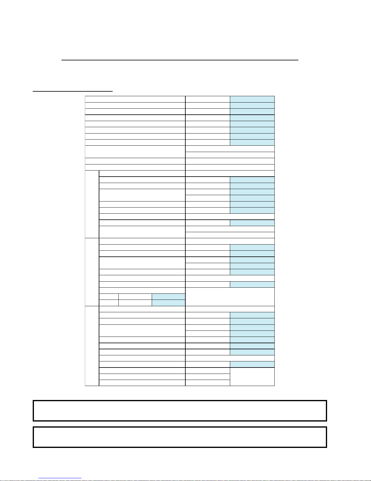
MAXIMUM CAPACITY (DRY WEIGHT) 170 lb 77.11 kg
TUMBLER DIAMETER 51-1/2” 130.81 cm
TUMBLER DEPTH 42-1/2” 107.95 cm
TUMBLER VOLUME 51.20 cu ft 1,449.82 L
TUMBLER/DRIVE MOTOR 1 hp 0.75 kW
BLOWER/FAN MOTOR 7-1/2 hp 5.59 kW
DOOR OPENING (DIAMETER) 31-3 /8 ” 79.69 cm
DOOR SILL HEIGHT 33-3/8” 84.77 cm
WATER CONNECTION 3/4”-11.5 NH
(North America)
3/4” B.S.P.T.
(Outside North America)
DRYERS PER 20’/40’ CONTAINER 3 / 7
DRYERS PER 48’/53’ TRUCK 8 / 9
VOLTAGE AVAILABLE 208-575V 3ø 3,4w 50/60 Hz
APPROXIMATE NET WEIGHT 2,103 lb 953.90 kg
APPROXIMATE SHIPPING WEIGHT 2,269 lb 1,029.20 kg
AIRFLOW 60 Hz 3,700 cfm 104.77 cmm
50 Hz 3,083 cfm 87.30 cmm
HEAT INPUT 550,000 Btu/hr 138,598 kcal/hr
EXHA UST C ONNECTION (DIAMETER) 1 8 ” 45.72 cm
COMPRESSED AIR CONNECTION 1/4” Quick Connection
COMPRESSED AIR VOLUME 4.25 cfh 0.12 cmh
INLET PIPE CONNECTION 1-1/2” F.N.P.T.
1-1/2” B.S.P.T.
(CE and Australia Only)
VOLTAGE AVAILABLE 416-460V 3ø 3,4w 50/60 Hz
APPROXIMATE NET WEIGHT 2,103 lb 953.90 kg
APPROXIMATE SHIPPING WEIGHT 2,269 lb 1,029.20 kg
AIRFLOW 60 Hz 3,700 cfm 104.77 cmm
50 Hz 3,083 cfm 87.30 cmm
EXHA UST C ONNECTION (DIAMETER) 1 8 ” 45.72 cm
COMPRESSED AIR CONNECTION 1/4” Quick Connection
COMPRESSED AIR VOLUME 4.25 cfh 0.12 cmh
OVEN SIZE
kW Btu/hr kcal/hr
126 429,900 108,300
VOLTAGE AVAILABLE 208-575V 3ø 3,4w 50/60 Hz
APPROXIMATE NET WEIGHT 2,259 lb 1,024.67 kg
APPROXIMATE SHIPPING WEIGHT 2,425 lb 1,099.96 kg
AIRFLOW 60 Hz 4,400 cfm 124.59 cmm
50 Hz 3,666 cfm 103.80 cmm
STEAM CONS UMPTION 7 2 5 l b /hr 328.85 kg/hr
OPERATING STEAM PRESSURE 125 psi max 8.62 bar
EXHA UST C ONNECTION (DIAMETER) 2 0 ” 50.80 cm
COMPRESSED AIR CONNECTION 1/4” Quick Connection
COMPRESSED AIR VOLUME 4.25 cfh 0.12 cmh
BOILER HORSEPOWER (NORMAL LOAD) 19 Bhp
SUPPLY CONNECTION 1-1/2” F.N.P.T.
RE TURN CONNEC TION 1 - 1 /2 ” F. N. P.T.
SECTION II
SPECIFICATIONS/COMPONENT IDENTIFICATION
A. SPECIFICATIONS
Gas
Electric
Steam

7
NOTE: ADC reserves the right to make changes in specifications at any time without notice or
obligation.
Specifications – Gas and Steam

8
B. COMPONENT IDENTIFICATION
1. Dryer Front View
Illus. No. Description
1 Microprocessor Control/Keypad Panel Assembly (controls)
2 Control (top access) Door Assembly
3 Main Door Assembly
4 Lint Drawer
5 Lint Door
6 Wire Diagram (located behind control door)
7 Data Label and Installation Label
8 Top Console (module) Assembly

9
2. Dryer Rear View
Illus. No. Description
1 Basket (drive) Motor Assembly
2 Blower Motor Mount Assembly
3 Idler Bearing Mount Assembly
4 Basket (tumbler) Bearing Mount Assembly
5* Electric Service Relay Box
6 Heating Unit
7 Data Label and Installation Label
8 1/8” Compressed Air Supply Inlet (behind gusset)
9 Side Access Opening
10 Front Access Opening
11 Impellor (fan) Assembly
* Electric service connections are made in this box.

10
SECTION III
INSTALLATION PROCEDURES
Installation should be performed by competent technicians in accordance with local and state codes. In the
absence of these codes, the installation must conform to applicable American National Standards: ANSI Z223.1-
LATEST EDITION (National Fuel Gas Code) or ANSI/NFPA NO. 70-LATEST EDITION (National Electrical
Code) or in Canada, the installation must conform to applicable Canadian Standards: CAN/CGA-B149.1-M91
(Natural Gas) or CAN/CGA-B149.2-M91 (Liquid Propane [L.P.] Gas) or LATEST EDITION (for General
Installation and Gas Plumbing) or Canadian Electrical Codes Parts 1 & 2 CSA C22.1-1990 or LATEST EDITION
(for Electrical Connections).
A. LOCATION REQUIREMENTS
Before installing the dryer, be sure the location conforms to local codes and ordinances. In the absence of such
codes or ordinances the location must conform with the National Fuel Gas Code ANSI.Z223.1 LATEST EDITION,
or in Canada, the installation must conform to applicable Canadian Standards: CAN/CGA-B149.1-M91 (Natural
Gas) or CAN/CGA-B149.2-M91 (L.P. Gas) or LATEST EDITION (for General Installation and Gas Plumbing).
1. The dryer must be installed on a sound level floor capable of supporting its weight. Carpeting must be
removed from the floor area that the dryer is to rest on.
IMPORTANT: “The dryer must be installed on noncombustible floors only.”
2. The dryer must not be installed or stored in an area where it will be exposed to water and/or weather.
3. The dryer is for use in noncombustible locations.
4. Provisions for adequate air supply must be provided as noted in this manual (refer to Fresh Air Supply
Requirements in Section D).
5. Clearance provisions must be made from combustible construction as noted in this manual (refer to Dryer
Enclosure Requirements in Section C).
6. Provisions must be made for adequate clearances for servicing and for operation as noted in this manual
(refer to Dryer Enclosure Requirements in Section C).
7. The dryer must be installed with a proper exhaust duct connection to the outside as noted in this manual
(refer to Exhaust Requirements in Section E).
8. The dryer must be located in an area where correct exhaust venting can be achieved as noted in this
manual (refer to Exhaust Requirements in Section E).
IMPORTANT: The dryer should be located where a minimum amount of exhaust duct will be
necessary.
9. The dryer must be installed with adequate clearance for air openings into the combustion chamber.

11
CAUTION: This dryer produces combustible lint and must be exhausted to the outdoors. Every 6
months, inspect the exhaust ducting and remove any lint build up.
IMPORTANT: The dryer must be installed in a location/environment, which the ambient
temperature remains between 40° F (4.44° C) and 130° F (54.44° C).
B. UNPACKING/SETTING UP
Remove protective shipping material (i.e., plastic wrap and/or optional shipping box) from dryer.
IMPORTANT: Dryer must be transported and handled in an upright position at ALL times.
The dryer can be moved to its final location while still attached to the skid or with the skid removed. To remove
skid from the dryer, locate and remove the four (4) lag bolts securing the base of the dryer to the wooden skid.
Two (2) are at the rear base, and two (2) are located in the bottom of the lint chamber. To remove the two (2)
lag bolts located in the lint chamber area, remove the lint drawer and the three (3) Phillips head screws securing
the lint door in place.
1. Leveling Dryer
a. To level the dryer, place 4-inch (10.16 cm) square metal shims or other suitable material under the base
pads. It is suggested that the dryer be tilted slightly to the rear (refer to the illustration above).
b. The V-belts are disconnected from the basket (tumbler) drive motor for shipping. Reconnect V-belts
before starting the dryer.

12
2. If more headroom is needed when moving the dryer into position, the top console (module) may be removed.
To Remove Top Console (module)...
a. Disconnect the ground wire (A in the illustration below) located at the rear upper left corner of the
dryer.
b. Remove the eight (8) sets of nuts and washers (B in the illustration below) holding the console (module)
to the base.
c. Disconnect the white plug connector (C in the illustration below) located on the top of the rear electric
service/relay box (provides power to the heat circuit).
d. Disconnect air connection from the 3-way micro valve.
e. Lift the console (module) off of the dryer base.
IMPORTANT: The dryer must be transported and handled in an upright position at ALL times.

13
C. DRYER ENCLOSURE REQUIREMENTS
Even though a 12-inch (30.48 cm) clearance is acceptable, it is recommended that the rear of the dryer be
positioned approximately 24-inches (60.96 cm) from the nearest obstruction (i.e., wall) for ease of installation,
maintenance, and service. Bulkheads and partitions should be made from noncombustible materials. The
clearance between the bulkhead header and the dryer must be a minimum of 4-inches (10.16 cm) and must not
extend more than 4-inches (10.16 cm) to the rear of the front. A 2-inch (5.08 cm) clearance is required between
the bulkhead facing and the top of the dryer.
NOTE: Bulkhead facing should not be installed until after the dryer is in place. Ceiling area must be
located a minimum of 12-inches (30.48 cm) above the dryer top console (module) and
18-inches (45.72 cm) for steam models.
NOTE: When fire sprinkler systems are located above the dryers, a minimum of 18-inches (45.72 cm)
above the dryer console (module) is required. Dryers may be positioned sidewall to sidewall,
however, 1 or 2-inches (2.54 or 5.08 cm) is suggested for ease of installation and
maintenance. Allowances must be made for the opening and closing of the control door and
the lint door.

14
D. FRESH AIR SUPPLYREQUIREMENTS
When the dryer is operating, it draws in room air, heats it, passes this air through the basket (tumbler), and
exhausts it out of the building. Therefore, the room air must be continually replenished from the outdoors. If the
make-up air is inadequate, drying time and drying efficiency will be adversely affected. Ignition problems and
sail switch “fluttering” problems may result, as well as premature motor failure from overheating. The dryer
must be installed with provisions for adequate combustion and make-up air supply.
Air supply (make-up air) must be given careful consideration to assure proper performance of each dryer. An
unrestricted source of air is necessary for each dryer. An airflow of 3,700 cfm (cubic feet per minute [104.77
cmm] [cubic meters per minute]) must be supplied to each gas dryer and 4,400 cfm (124.59 cmm) must be
supplied to each steam dryer. As a general rule, an unrestricted air entrance from the outdoors (atmosphere) of
a minimum of 4 square feet (0.37 square meters) is required for each gas dryer and a minimum of 4.75 square
feet (0.44 square meters) for each steam dryer.
To compensate for the use of registers or louvers used over the openings, this make-up air must be increased by
approximately thirty-three percent (33%). Make-up air openings should not be located in an area directly near
where exhaust vents exit the building.
It is not necessary to have a separate make-up air opening for each dryer. Common make-up air openings are
acceptable. However, they must be set up in such a manner that the make-up air is distributed equally to ALL
the dryers.
EXAMPLE: For a bank of six (6) dryers, 2 unrestricted openings measuring 3 feet by 4 feet (12 square feet
[0.91 meters by 1.22 meters] [1.11 square meters]) are acceptable.
Allowances must be made for remote or constricting passageways or where dryers are located at excessive
altitudes or predominantly low pressure areas.
IMPORTANT: Make-up air must be provided from a source free of dry cleaning solvent fumes.
Make-up air that is contaminated by dry cleaning solvent fumes will result in
irreparable damage to the motors and other dryer components.
NOTE: Component failure due to dry cleaning solvent fumes will VOID THE WARRANTY.

15
E. EXHAUST REQUIREMENTS
1. General Exhaust Ductwork Information
Exhaust ductwork should be designed and installed by a qualified professional. Improperly sized ductwork
will create excessive back pressure, which results in slow drying, increased use of energy, overheating of
the dryer, and shutdown of the burner by the airflow (sail) switches, burner hi-limits, or basket (tumbler)
hi-heat thermostats. The dryer must be installed with a proper exhaust duct connection to the outside.
CAUTION: This dryer produces combustible lint and must be exhausted to the outdoors.
CAUTION: IMPROPERLY SIZED OR INSTALLED EXHAUST DUCTWORK CAN
CREATE APOTENTIAL FIRE HAZARD.
NOTE: When a dryer is exhausted separately, it is recommended that a back draft damper be
installed.
NOTE: When dryers are exhausted into a multiple (common) exhaust line, each dryer must be
supplied with a back draft damper.
The ductwork should be laid out in such a way that the ductwork travels as directly as possible to the
outdoors with as few turns as possible. Single or independent dryer venting is recommended.
When single dryer venting is used, the ductwork from the dryer to the outside exhaust outlet should not
exceed 20 feet (6.09 meters). In the case of multiple (common) dryer venting, the distance from the last
dryer to the outside exhaust outlet should not exceed 20 feet (6.09 meters). The shape of the ductwork
is not so critical so long as the minimum cross-sectional area is provided. It is suggested that the use of 90º
turns be avoided; use 30º and/or 45º bends/angles instead. The radius of the elbows should preferably be
1-1/2 times the diameter of the duct. Excluding basket (tumbler)/dryer elbow connections or elbows used
for outside protection from the weather, no more than two (2) elbows should be used in the exhaust duct
run. If more than two (2) elbows are used, the cross-sectional area of the ductwork must be increased in
proportion to the number of elbows used.
ALL ductwork should be smooth inside with no projections from sheet metal screws or other obstructions,
which will collect lint. When adding ducts, the duct to be added should overlap the duct to which it is to be
connected. ALL ductwork joints must be taped to prevent moisture and lint from escaping into the
building. Inspection doors should be installed at strategic points in the exhaust ductwork for periodic
inspection and cleaning of lint from the ductwork.
IMPORTANT: Exhaust back pressure measured by a manometer in the exhaust duct must be no less
than 0 and must not exceed 0.3 inches (0.74 mb) of water column (W.C.).
NOTE: When the exhaust ductwork passes through a wall, ceiling, or roof made of combustible
materials, the opening must be 2-inches (5.08 cm) larger than the duct (all the way around).
The duct must be centered within this opening.
IMPORTANT: It is recommended that exhaust or booster fans not be used in the exhaust ductwork
system.

16
NOTE: As per the National Fuel Gas Code, “Exhaust ducts for Type 2 clothes dryers shall be
constructed of sheet metal or other noncombustible material. Such ducts shall be equivalent in
strength and corrosion resistance to ducts made of galvanized sheet steel not less than 26
gauge (0.0195-inches [0.50 mm]) thick.”
a. Outside Ductwork Protection
1) To protect the outside end of the horizontal ductwork from the weather, a 90° elbow bent downward
should be installed where the exhaust exits the building. If the ductwork travels vertically up
through the roof, it should be protected from the weather by using a 180° turn to point the opening
downward. In either case, allow at least twice the diameter of the duct between the duct opening
and the nearest obstruction.
IMPORTANT: DO NOT use screens, louvers, or caps on the outside opening of the exhaust
ductwork.
2. Single Dryer Venting
Where possible, it is suggested to provide a separate exhaust duct for each dryer. The exhaust duct should
be laid out in such a way that the ductwork travels as directly as possible to the outdoors with as few turns
as possible. It is suggested that the use of 90° turns in the ducting be avoided; use 30° and/or 45° angles
instead. The shape of the exhaust ductwork is not critical so long as the minimum cross section area is
provided.
IMPORTANT: The minimum duct size for a gas unit is 18-inches (45.72 cm) for a round duct
16-inches x 16-inches (40.64 cm x 40.64 cm) for a square duct and for a steam unit
20-inches (50.80 cm) for a round duct and 18-inches x 18-inches (45.72 cm x 45.72
cm) for a square duct. THE DUCT SIZE MUST NOT BE REDUCED
ANYWHERE DOWNSTREAM OF THE DRYER.
IMPORTANT: Exhaust back pressure measured by a manometer at each basket (tumbler) exhaust
duct area must be no less than 0 and must not exceed 0.3 inches (0.74 mb) of water
column (W.C.).
Table of contents
Other ADC Dryer manuals
Popular Dryer manuals by other brands

Shini
Shini SHD Series manual

Sears
Sears Kenmore Advantage 64781 operating instructions

Kenmore
Kenmore 796.8077 series Use & care guide and installation instructions

Siemens
Siemens WQ45G209GR User manual and installation instructiions

Asko
Asko T411HSW installation instructions

Miele
Miele PDR 908 EL Operating and installation instructions