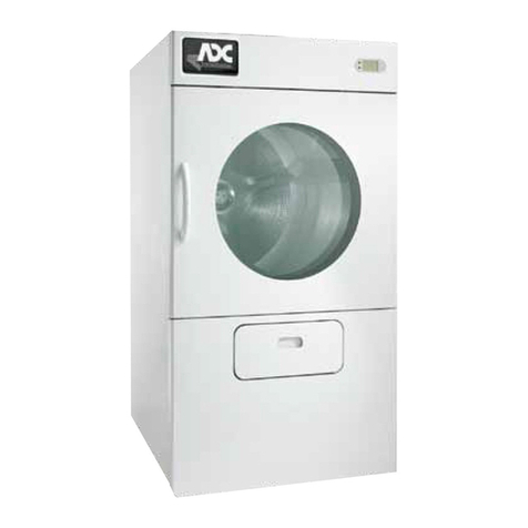
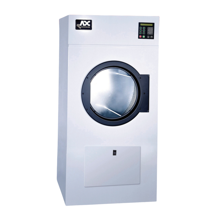
ADC AD-95 User manual

AmericanDryerCorporation
88 Currant Road
FallRiver,MA 02720-4781
Telephone: (508) 678-9000 / Fax: (508) 678-9447
E-mail: [email protected]
072298SL/cj ADCPartNo.450188
AD-95/ML-95
Service Manual

Retain This Manual In A Safe Place For Future Reference
Replacement parts can be obtained from your distributor or the ADC factory. When ordering replacement parts from the
factory, you can FAX your order toADCat(508)678-9447or telephone yourorders directly totheADC PartsDepartmentat
(508) 678-9000. Please specify the dryermodelnumber andserialnumberinadditiontothedescriptionandpartnumber,so
that your order is processed accurately and promptly.
Theillustrationsonthefollowing pages maynotdepictyourparticulardryer exactly. The illustrationsareacompositeofthe
various dryer models. Be sure to check the descriptions of the parts thoroughly before ordering.
DATE OF PURCHASE MODEL NO.
DISTRIBUTORS NAME
Serial Number(s)
“IMPORTANT NOTE TO PURCHASER”
Information must be obtained from your local gas supplier on the instructions
to be followed if the user smells gas. These instructions must be posted in a
prominent location near the dryer.
American Dryer Corporation products embody advanced concepts in engineering, design, and safety. If this product is
properly maintained, it will provide many years of safe, efficient, and trouble-free operation.
ONLY qualified technicians should service this equipment.
OBSERVEALL SAFETY PRECAUTIONS displayed on the equipment or specified in the installation/operator's manual
included with the dryer.
The following “FOR YOUR SAFETY” caution must be posted near the dryer in a prominent location.
FOR YOUR SAFETY
Do not store or use gasoline or
other flammable vapors or liquids
in the vicinity of this or any other
appliance.
POUR VOTRE SÉCURITÉ
Ne pas entreposer ni utiliser d’essence
ni d’autres vapeurs ou liquides
inflammables dans le voisinage de cet
appareil ou de yout autre appareil.
We have tried to make this manual as complete as possible and hope you will find it useful. ADC reserves the right to make
changes from time to time, without notice or obligation, in prices, specifications, colors, and material, and to change or
discontinue models.
Important
For your convenience, log the following information:

IMPORTANT
YOU MUST DISCONNECT and LOCKOUT THE ELECTRIC SUPPLY and THE GAS
SUPPLY or THE STEAM SUPPLY BEFORE ANY COVERS or GUARDS ARE
REMOVEDFROMTHEMACHINETOALLOWACCESS FORCLEANING,ADJUST-
ING, INSTALLATION, or TESTING OF ANY EQUIPMENT per OSHA (Occupational
Safety and Health Administration)STANDARDS.
CHILDREN SHOULD NOT BE ALLOWED TO PLAY ON OR NEAR THE DRYER(S).
WARNING
CHILDREN SHOULD BE SUPERVISED IF NEAR DRYERS IN OPERATION.
DRYERS SHOULD NEVER BE LEFT UNATTENDED WHILE IN OPERATION.
CAUTION
FOR YOUR SAFETY
DO NOT DRY MOP HEADS IN THE DRYER.
DO NOT USE DRYER IN THE PRESENCE OF DRY CLEANING FUMES.
WARNING
UNDERNOCIRCUMSTANCESshouldthedoorswitchortheheatcircuitdevicesever
be disabled.
“Caution: Label all wires prior to
disconnection when servicing controls. Wiring
errors can cause improper operation.”
«Attention: Lordesopérationsd’entretien
des commandes étiqueter tous fils avant
de les déconnecter. Toute erreur de
câblage peut étre une source de danger et
de panne.»

WARNING
The dryer must never be operated with any of the back guards, outer tops, or service
panels removed. PERSONAL INJURY or FIRE COULD RESULT.
IMPORTANT
PLEASE OBSERVEALLSAFETYPRECAUTIONSdisplayedontheequipmentand/or
specified in the installation and operator's manual included with the dryer.
Dryers must not be installed or stored in an area where it will be exposed to water or
weather.
The wiring diagram for the dryer is located in the front electrical control box area.
DRYER MUST NEVER BE OPERATED WITHOUT THE LINT FILTER/SCREEN IN
PLACE, EVEN IF AN EXTERNAL LINT COLLECTION SYSTEM IS USED.
WARNING

Table of Content
SECTIONI
Important Information...........................................................................................................................3
A. Safety Precautions...............................................................................................................................3
SECTIONII
Maintenance ..........................................................................................................................................4
A. Cleaning..............................................................................................................................................4
B.Adjustments.........................................................................................................................................5
C. Lubrication ..........................................................................................................................................5
SECTIONIII
Installation Requirements.....................................................................................................................6
A.Enclosure,AirSupply,andExhaustRequirements ..................................................................................6
B.ElectricalandGasRequirements...........................................................................................................6
C. Operational Service Check Procedure ...................................................................................................7
SECTIONIV
Desciption of Parts ................................................................................................................................8
A.ComputerPanel(Microprocessor) ........................................................................................................8
B.Reversing RelayPanel .........................................................................................................................9
C. HSI Module (for Gas Models ONLY) .................................................................................................10
D.GasBurnerAssembly ........................................................................................................................10
E. Drive Motor....................................................................................................................................... 11
F. BlowerMotorandImpellor ................................................................................................................ 11
G.DriveShaftAssembly .........................................................................................................................12
H.IdlerShaftAssembly ..........................................................................................................................13
I. Basket (Tumbler) ...............................................................................................................................14
J. Main Door Switch..............................................................................................................................14
K. Sail Switch (for Gas Models ONLY) ...................................................................................................15
L.Hi-Limit(for Gas ModelsONLY) .......................................................................................................15
M.Automatic ResetThermostat..............................................................................................................16
N. Lint Screen .......................................................................................................................................16
O. Lint Drawer Switch ...........................................................................................................................17
SECTIONV
Servicing ..............................................................................................................................................18
A.ComputerControls.............................................................................................................................18
B. Ignition Controls.................................................................................................................................20
C. Thermostats ......................................................................................................................................23
D.Sail SwitchAssembly (forGas Models ONLY)....................................................................................24
E.FrontPanelandMainDoorAssemblies ...............................................................................................25
F. Pulleys ..............................................................................................................................................28
G.BasketAssembly ................................................................................................................................32
H.Bearings ...........................................................................................................................................33
I. V-Belts..............................................................................................................................................33
J. Motors ..............................................................................................................................................34
K. Impellor ............................................................................................................................................37
L.Lint DrawerAssembly .......................................................................................................................37

SECTIONVI
Troubleshooting ..................................................................................................................................38
SECTIONVII
Phase 6 OPL System Diagnostics .......................................................................................................41
A.Diagnostic (L.E.D.Display) FailureCodes ..........................................................................................41
B.LED DisplayIndicators ......................................................................................................................43
C. L.E.D. Codes ....................................................................................................................................48
D.ComputerLogic and WiringDiagram ..................................................................................................50
SECTIONVIII
Technical Information..........................................................................................................................56
A. Motor Plate (High and Low Voltage) ..................................................................................................56
B. Data Label ........................................................................................................................................57
C. Using a Manometer ...........................................................................................................................58
D.ToolList............................................................................................................................................59

3
SECTION I
A. Safety Precautions
1. DO NOT store or use gasoline or other flammable vapors and liquids in the vicinity of this or any other
appliance.
2. Purchaseroruser should consultthelocal gas supplierforproperinstructions to befollowedin the eventthe
user smells gas. The instructionsshouldbe postedinaprominent location.
3. Dryer must be exhausted to the outdoors.
4. Although ADC'sdryer is a very versatile machine, there are some articles, that due to fabric composition or
cleaningmethod,shouldnotbedriedinit.
WARNING: Dry only water-washed fabrics. DONOT dry articles spotted or washed in dry
cleaningsolvents,a combustible detergent,or"all-purpose"cleaners. Fire or
explosion could result.
WARNING: DO NOT dry rags or articles coated with gasoline, kerosene, paint, or wax. Fire or
explosion could result.
WARNING: DONOT dry mop heads. Contamination by wax or flammable solvents will create
a fire hazard.
WARNING: DONOT use heat for drying articles that contain plastic, foam, sponge rubber, or
similarly textured rubberlike materials. Drying in a heated tumbler may damage plastic
orrubber and alsomaybe a firehazard.
5. A programshouldbe established for the inspection and cleaning of lint in the burner area and exhaust duct
work. The frequency of cleaning can best be determined from experience at each location.
WARNING: The collection of lint in the burner area and exhaust duct work can create
a potential fire hazard.
6. For personal safety, the dryermust be electrically grounded in accordance with local codes and the National
Electric Code ANSI/NFPA No. 70-LATEST EDITION.
NOTE: Failureto doso willvoid the warranty.
7. Underno circumstances shouldthedryer door, lintdrawerswitches or heatsafetydevices ever bedisabled.
WARNING: PERSONAL INJURY OR FIRE COULD RESULT.
8. Articles should never be left unattended for an extended period of time in the basket after completion of the
drying and cooling cycles.
9. Thisdryer is notto be usedinthe presence ofdry cleaning solventsorfumes.
10. Read and followALL caution anddirection labels attachedto dryer.
WARNING: CHILDREN SHOULD NOT BE ALLOWED TO PLAY ON OR IN THE DRYERS
CHILDREN SHOULD BE SUPERVISED IF NEAR DRYERS IN OPERATION.
Important Information

4
A. Cleaning
A program and schedule should be established for periodic inspection, cleaning,and removalof lintfrom various
areasofthe dryer, aswellasthroughout the ductworksystem. Thefrequency of cleaningcanbestbe determined
fromexperienceateach location. Maximum operating efficiencyisdependentuponproperair circulation. The
accumulationoflintcanrestrictthisairflow. Iftheguidelinesinthissectionaremet,an ADC dryer will provide
many years of efficient, trouble free, and – most importantly – safe operation.
WARNING: LINT FROM MOST FABRICS IS HIGHLY COMBUSTIBLE. THE
ACCUMULATION OF LINT CAN CREATE A POTENTIAL FIRE HAZARD.
WARNING: KEEP DRYER AREA CLEAR AND FREE FROM COMBUSTIBLE MATERIALS,
GASOLINE AND OTHER FLAMMABLE VAPORS AND LIQUIDS.
NOTE: Suggested time intervals shown for average usage which is considered six (6) to eight (8)
operational(running)hoursperday.
Clean lint drawer and screen every third load.
NOTE: Frequency can best be determined at each location.
Daily (beginning) of each work shift.
Clean lint from the drawer and screen. Inspect lint screen and replace if torn.
Weekly
Cleanlintaccumulation from lintchamber, thermostatandmicroprocessortemperature sensor (sensor bracket)
area.
WARNING: To avoid the hazard of electrical shock, discontinue electrical supply to dryer.
90 Days
Remove lint from basket, drive motors and surrounding areas. Remove lint from gas valve burner area with a
dusting brush or vacuum cleaner attachment.
NOTE: Toprevent damage,avoidcleaningortouching ignitorandflame-probeassembly.
Remove lint accumulation from inside control box and at rear area behind control box.
6 Months
Inspectandremovelintaccumulationincustomer-furnishedexhaustductworksystemandfromdryer'sinternal
exhaustducting.
SECTION II
Routine Maintenance

5
WARNING: THE ACCUMULATION OF LINT IN THE EXHAUST DUCT WORK CAN CREATE
A POTENTIAL FIRE HAZARD.
WARNING:
Do not obstruct the flow of combustion and ventilation air. Check customer furnished back
draft damper in exhaust duct work. Inspect and remove any lint accumulation which can
cause damper to bind or stick.
NOTE: A back draft damper that is sticking partially closed can result in slow drying and shutdown of the
heat circuits safety switches or thermostats.
NOTE: When cleaning dryer cabinets, avoid using harsh abrasive. A product intended for cleaning
appliances is recommended.
B.Adjustments
Seven Days after Installation and every 6 Months
Inspect bolts, nuts, screws (bearing set screws), nonpermanent gas connections (union, shut-off valves, orifices,
andgroundconnections). Motoranddrive belts should beexamined. Crackedorseriouslyfrayedbeltsshould be
replaced. Tightenloose V-beltswhen necessary. Complete operationalcheck of controlsand valves. Complete
operationalcheckofall safety devices (doorswitch,lintdrawerswitch,sail switch, burner andhi-limitthermostats).
C. Lubrication
The motor bearings, idler bearings, and basket (tumbler) bearings are permanently lubricated. No lubrication is
necessary.
Theimpeller (fan)shaft bearingshould belubricated every three (3) months.

6
Installation should be performed by competent technicians in accordance with local and state codes. In the
absence of these codes, installation must conform to applicable AMERICAN NATIONAL STANDARDS:
National Fuel Gas Code ANSI Z223.1-LATEST EDITION or National Electric Code ANSI/NFPA No. 70-
LATEST EDITION, or Canadian Electrical Codes Parts 1 & 2 CSA C22.1-1990 or LATEST EDITION
(forElectricalConnections).
A. Enclosure, Air Supply, and Exhaust Requirements
NOTE: Thefollowing informationis verybrief andgeneral. For detaileddescription, refer
totheAD-95 Installation Manual supplied withdryer. (ADCP/N 112197)
Bulkheads and partitions around the dryershould be made ofnoncombustiblematerials. Allowances should
be madefor the openingand closing ofthecontrol doorandlint door. (Refer toappropriate installation manualfor
recommendeddistancesandminimumallowancesrequired.)
When the dryer is operating, it draws in room air, heats it, passes this air through the basket (tumbler), and
exhaustsit outof the building. Therefore,the roomair must becontinually replenishedfrom the outdoors. Ifthe
makeupairisinadequate,dryingtimeanddrying efficiency will be adversely affected. Ignitionproblems and sail
switch "fluttering" problems on gas dryers may result, and you also could have premature motor failure from
overheating. The air supplymust be given careful consideration to insure proper performance of each dryer.
IMPORTANT: Makeup airmust be provided from a source free of dry cleaning fumes. Makeup air
thatiscontaminatedbydrycleaning fumes will result inirreparable damage tomotors
andother dryercomponents.
Exhaustduct workshould be designedandinstalled by acompetenttechnician. Improperly sized ductworkwill
create excessive back pressure which will result in slow drying, increased use of energy, and shutdown of the
burnerby the airflow(sail) switch, burnerhi-limitor lint chamberhi-heat protector thermostat. (Refertoappropriate
Installation Manual for more detail.)
CAUTION: IMPROPERLY SIZED OR INSTALLED EXHAUST DUCT WORK CAN
CREATE A POTENTIAL FIRE HAZARD.
B. Electrical and Gas Requirements
It is your responsibility to have ALL electrical connections made by a properly licensed and competent
electricianto assure theelectricalinstallation is adequateandconforms with localandstate regulations orcodes.
In the absence of such codes,ALLelectrical connections, material, and workmanship must conform to the
applicable requirements of the National Electric Code ANSI/NFPA No. 70-LATEST EDITION, or Canadian
Electrical Codes Parts 1 & 2 CSA C22.1-1990 or LATEST EDITION (for Electrical Connections).
IMPORTANT: Failuretocomply with these codesorordinances and the requirements
stipulatedin thismanualcanresultinpersonalinjury orcomponent failure.
SECTION III
Installation Requirements

7
The dryer installationmust meet the AMERICAN NATIONAL STANDARD,NATIONALFUELGAS CODE
ANSI Z223.1-LATEST EDITION, as well as, local codes and ordinances, andmust be done by a qualified
technician, or Canadian Electrical Codes Parts 1 & 2 CSA C22.1-1990 or LATEST EDITION
(forElectricalConnections).
NOTE: Undersized gas piping will result in ignition problems and slow drying and can create a safety
hazard.
The dryer must be connected to the type of gas (natural or L.P.) indicated on the dryer data label. If this
informationdoes not agreewiththe type ofgasavailable, contact thedistributorwho soldthedryer or contactthe
factory.
The gas input ratings shown on the dryer data label are for elevations up to 2,000 feet, unless elevation require-
mentsof over2,000 feet werespecified atthe time thedryer orderwas placed withthe factory. Theadjustment
for dryers in the field for elevations over 2,000 feet are made by changing the burner orifices. If this adjustment
isnecessary, contactthedistributor whosoldthe dryerorcontact thefactory.
NOTE: Any burner changes must bemadeby a qualifiedtechnician.
C. Operational Service Check Procedure
1. Turn on electric power to the dryer.
2. To start dryer:
a.Displaywillread"READY"
b. Press "E" touch pad on the keyboard of microprocessor controller (computer).
c. The dryer will start and display will show "dRYING MANUAL CYCLE, 30 MIN REMAIN,"
then display the drum temp.
NOTE: Pressing touch pads A, B, C, D and F will also start the dryer. Six (6) preprogrammed drying
cycles (A through F) have been stored in the computer's memory. (See computer operator's
manual for details.)
3. Make a complete operational check of all the operating controls to assure that the timing is correct,
temperature selection switches are functioning, etc.
4. Make a complete operational check of all safety-halted circuits: door switches, hi-limit thermostat, sail
switch, cycling thermostats, etc.
5. For gas dryers a gas pressure test should be taken at the gas valve pressure tap of each dryer to assure
that the water column pressure is correct and consistent.
NOTE: Water column pressure requirements (measured at the pressure tap on the gas valve body):
Natural Gas - 3.5 to 4 inch water column
L.P. Gas - 10.5 to 11 inch water column.
6. If computer program changes are required, refer to the Phase 6 OPL Operator's Manual (ADC P/N
113022) for details.
7. The dryer should be operated through one complete cycle to assure that no further adjustments are neces-
sary and that all components are functioning properly.
8. Check the electric service phase sequence. While the dryer is operating, check to see if the blower wheel
is rotating in the proper direction. Looking from the front, the blower wheel should spin in the clockwise
direction. If so, the phasing is correct. If the phasing is incorrect, reverse two (2) leads at connections L1,
L2 or L3 of power supply to the dryer.

8
SECTION IV
Description of Parts
A. Control Panel (Microprocessor)
Liftingthe controldoorwill revealthecontrol panelas-
sembly. Opening the control panel will allow access to
themajorcomponentswhichincludethecomputerboard
and keypad. The keypad inputs to the computer what
temperature and program has been selected. The com-
puter controls the entire operation of the machine. It
acceptsinputsandgivesoutputsthroughoutthemachine.
prior to February 11, 1998
as of February 11, 1998

9
B. Reversing Relay Panel
Lifting the control door will reveal the reversing relay
box. Located on the back of the relay box is the revers-
ingrelaypanel. Includedonthispanelisafour(4)posi-
tionterminal block,bloweroverload, blowercontactor,
reversingcontactor, 24VACtransformer,fuse orcircuit
breaker,ground lug andanarc suppressor (A.S.)board.
...with fuses
...with circuit breaker

10
D. Gas Burner Assembly
Gas-heated dryers are equipped with a gas
burnerassemblyconsistingofthree(3)burner
tubes, gas valve, glo bar, flame sensor, sail
switch, and hi-limit thermostat. The inlet
pipingenters through therearof the dryeron
the left-hand side (viewing from the front)
and runs to the front of the dryer where the
gasvalve islocated.
C. HSI Module (Gas Models
Only)
The HSI system consists of a microprocessor-
based control module, along with a hot surface
ignitorprobeandaflameprobeassembly. The
hotsurfaceignitorisasiliconcarbideignitorthat
upon application of 24VAC will glow bright
orange for the inter-purge time period. Upon
ignition, the resistance in the flame sensor
electrode changes and the information is sent
to the HSI module via the sensor probe lead
connection to the module. Once the resistance
is changed and sensed, the HSI module will
sustainthegasflow (provide 24VACpowerto
the gas valve).

11
E. Drive Motor
TheTEFC(totallyenclosed,fan-cooled)drivemo-
torislocatedinthe front leftcorner (viewingfrom
front) behind the front panel of the dryer. It sits
on an adjustable base so the motor can be easily
adjusted to the left or right, up or down, forward
orbackward. The drivemotor is a1/2 HPmotor
and operates on 208 to 460 volts, 50/60 hertz, 3-
phase.
F. Blower Motor and Impeller
Theimpeller is shaftdriven. Theblower mo-
tor drives the shaft on which the impeller is
mounted. Thisenables the impellertorun at
a higher RPM, thereby producing a higher
airflow (CFM).
NOTE: The bearing on this type of blower assemblyshouldbe greased according to the maintenance
sectionofthismanual.

12
G.DriveShaftAssembly
(Viewingfromthe front ofthedryer.) Behindfront panel
onthe leftsideof thedryer,you canviewthe driveshaft
assembly which consists of a 9" drive pulley, two (2) 6"
wheels,two(2)trantorques,onmodelsmanufacturedprior
to December 15, 1997; or with two (2) taperlock bear-
ings,onmodelsmanufacturedafterDecember15,1997;
and two (2) 1" pillow block bearings.
trantorque
taperlock

13
H. Idler Shaft Assembly
(Viewingfromthefrontofthedryer.)Behindthefrontpanelontherightsideofthedryeryouwillviewthe
idlershaftassembly which consistsoftwo (2) 6"wheels, two (2)transtorqueon models manufactured
priorto December15,1997; orwith two(2)taperlock bearingson modelsmanufacturedafter December
15,1997;and two (2)1"pillow block bearings.
transtorque
taperlock

14
J. Main Door Switch
The main door switch is mounted to the front panel
behind the main door. When the main door opens,
theswitchwillalsoopen,preventingthedryerfrom
operating. The main door switch is a safety device
andshouldneverbedisabled.
I. Basket (Tumbler)
Thebasketconsistsof a basket(tumbler)weldment
which have four (4) ribs and four (4) removable
perforated panels which are mounted to the rib
sections of the basket (tumbler) weldment with
1/4-20 x 1/4" socket button head screws.

15
K. Sail Switch (Gas Models Only)
The sail switch is located on the front of the burner box. A sail switch
consistsof a rounddamperplate onalever arm whichisin contactwith
an electric switch. When the fan or air blower comes on, it draws air
through the gas burner. This creates a negative pressure inside the
burner box, and this negative pressure pulls in the round damper and
activates the sail switch. If there is improper air flow, the damper will
not pull in, preventing the burner from starting. The display will also
read"noairflowflow"withanaudioindication. Improperairflowcanbe
caused by improperly designed exhaust ducting where the duct run is
too long or has too many sharp bends in it. It can also be caused by a
lack of makeup air.
L. Hi-Limit(GasModels Only)
Prior to May 26, 1998. The high limit thermostat is an
automatic reset disc-type thermostat set at 330º Fand
located near the burner. If the burner flame gets too hot,
this thermostat will shut off the burner. This is generally
caused by low airflow through the dryer. In a hi-limit
situation the display will read "bURNER SAFETY FAIL"
with an audio indication.
As of May 26, 1998. The high limit thermostat is a
manual reset disc-type thermostat set at 330º F and lo-
cated near the burner. If the burner flame gets too hot,
this thermostat will shut off the burner. This is generally
caused by low airflow through the dryer. In a hi-limit
situation the display will read "bURNER SAFETY FAIL"
with an audio indication. The manual reset thermostat
must be reset manually or the 24VAC burner circuit will
never be complete. This will cause the phase 6 to con-
tinue to go off on "bURNER SAFETY FAIL" with an
audio indication.

16
M. Automatic Reset Thermostat
This is located inside the dryer in the lint com-
partmentabovethelint screen. This thermostat
senses the heated air after it passes through the
basket. If the air temperature gets too hot, the
thermostat will shut off the burner. The dryer
willnotrununtiltheairtemperaturecoolsdown.
At this time, the thermostat will reset. Basket
andblower willrun butthe dryerwill not heat. If
thetemperaturesensoropens the displaywillread
"TEMP SENSOR FAIL CHECK TEMP SEN-
SORFUSE"withanaudioindication. Ifthether-
mostat opens the display will read "dRUM
SAFETY FAIL" with an audio indication.
N. Lint Screen
The lint screen is located in the front of the dryer
behind the lint door it is a non-removable framed
screen which is screwed into the lint coupe. To
clean the lint off the screen simply brush the screen
clean. The lint screen must be kept clean in order
for the dryer to operate properly and efficiently.
Inspect the screen for tears and replace as needed.
This manual suits for next models
1
Table of contents
Other ADC Dryer manuals