LTPH-TP-1003-02, Issue 2 Table of Contents
HRE-206 Lists 1 and 2 June 1, 2001 v
TABLE OF CONTENTS
Overview ____________________________________________________________________________ 1
Features..............................................................................................................................................2
Applications .......................................................................................................................................2
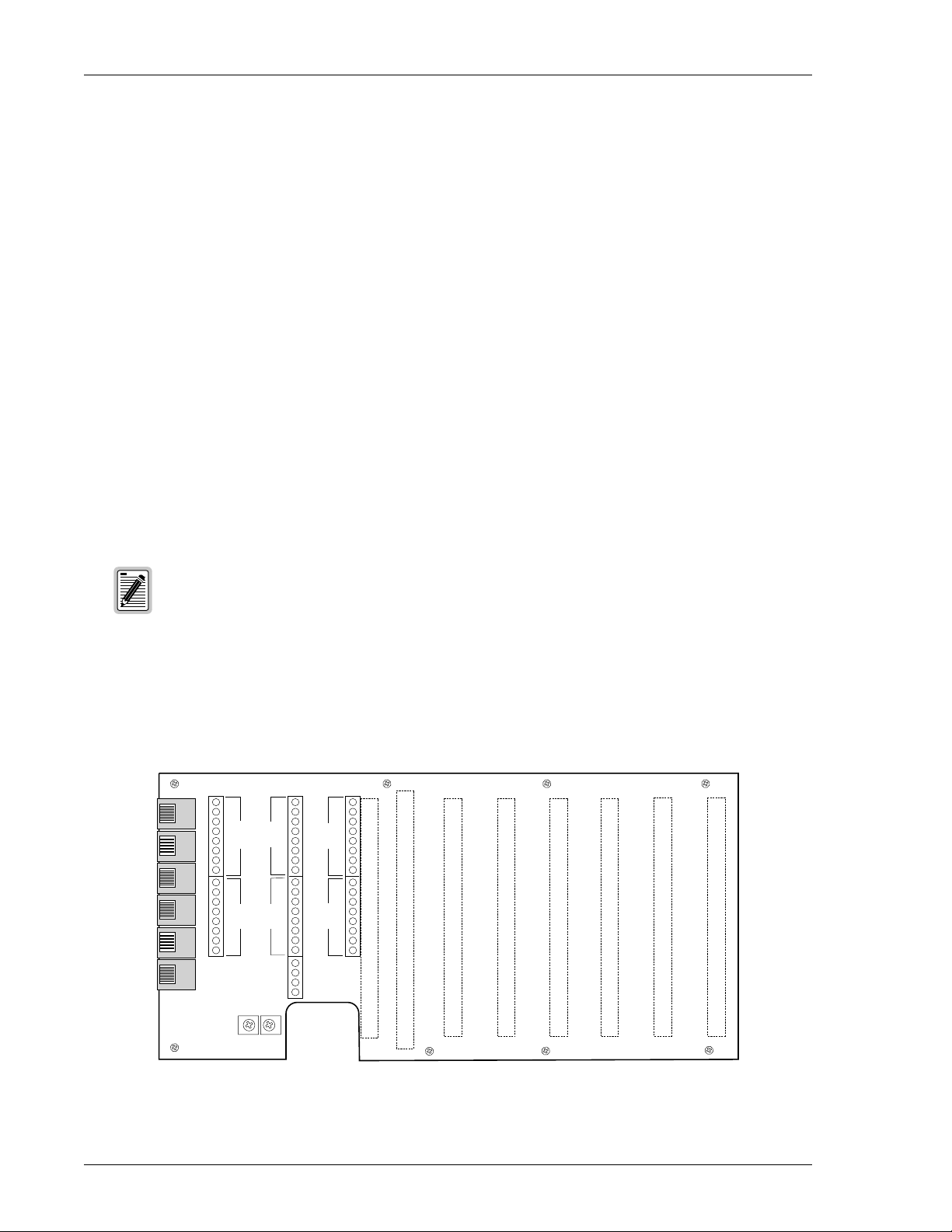
Backplane...........................................................................................................................................2
Slot Connectors..................................................................................................................................4
Installation___________________________________________________________________________ 4
Installation Kit....................................................................................................................................4
Mounting Options..............................................................................................................................5
Desktop Mounting...............................................................................................................5
Wall Mounting.....................................................................................................................5
Turn-Up..............................................................................................................................................7
Power and Grounding _________________________________________________________________ 7
48 Volt Power Options.......................................................................................................................8
Slot Pin Assignments __________________________________________________________________ 9
HLU Alarm Output Interface...........................................................................................................13
Facility Side HDSL Connections.....................................................................................................13
CPE DS1 (G.703) Connections........................................................................................................15
Appendix A - Specifications____________________________________________________________ 17
Appendix B - Product Support _________________________________________________________ 18
Technical Support............................................................................................................................18
Returns.............................................................................................................................................18
Appendix C - Abbreviations ___________________________________________________________ 20
Certification and Warranty______________________________________________ Inside Back Cover


 user manual")