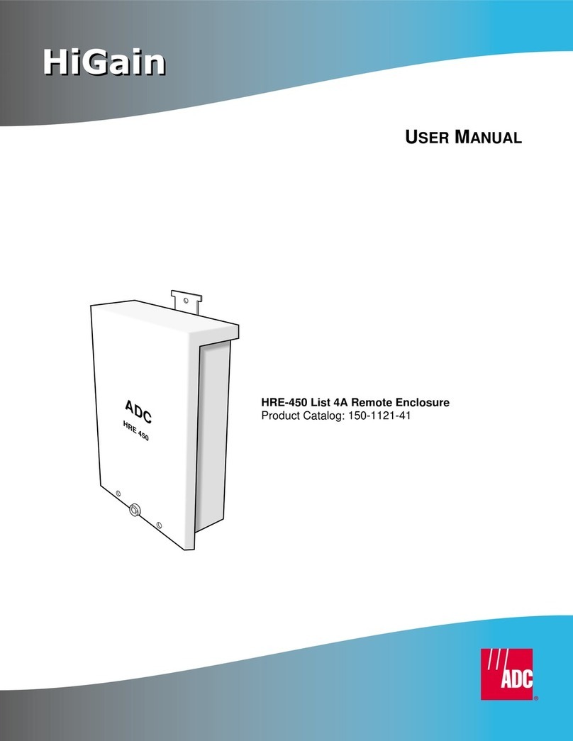
ADC HiGain HRE-450 List 4A User manual

HiGain
HiGain
HIGAIN REMOTE ENCLOSURE
ADC TELECOMMUNICATIONS, INC.
USER MANUAL
SECTION 150-450-132-02
Model List Number Part Number CLEI Code
HRE-450 2B 150-1121-22 T1RHCGS4
HRE-450 3B 150-1121-32 T1M11N0C
HRE-450 4B 150-1121-42 T1M12N0C

150-450-132-02, Issue 2
ii March 6, 2000 HRE-450List 2B, List 3B, & List 4B
Revision History of This Manual
Copyright
March 6, 2000
© 2000 ADC DSL Systems, Inc. All rights reserved.
Trademark Information
ADC is a registered trademark of ADC Telecommunications, Inc. HiGain is a registered trademark of ADC DSL Systems, Inc.
No right, license, or interest to such trademarks is granted hereunder, and you agree that no such right, license, or interest
shall be asserted by you with respect to such trademark. Other product names mentioned in this practice are used for
identification purposes only and may be trademarks or registered trademarks of their respective companies.
Disclaimer of Liability
Information contained in this document is company privateto ADC DSL Systems, Inc.,and shall not be modified, used, copied,
reproduced or disclosed in whole or in part without the written consent of ADC.
Contents herein are current as of the date of publication. ADC reserves the right to change the contents without prior notice.
In no event shall ADC be liable for any damages resulting from loss of data, loss of use, or loss of profits, and ADC further
disclaims any and all liability for indirect, incidental, special, consequential or other similar damages. This disclaimer of
liability applies to all products, publications and services during and after the warranty period.
Revision Release Date Revisions Made
01 March 6, 2000 Initial Release
02 January 7, 2002 ADC Rebranding
150-450-132-02, Issue 2 Using This Manual
HRE-450 List 2B, List 3B, & List 4B March 6, 2000 iii
USING THIS MANUAL
The following conventions are used in this manual:
For a list of abbreviations used in this document, refer to “Appendix B - Product Support” on page 14.
INSPECTING THE SHIPMENT
Upon receipt of the equipment:
•Unpack each container and inspect the contents for signs of damage. If the equipment has been damaged in
transit, immediately report the extent of damage to the transportation company and to ADC. Order
replacement equipment if necessary.
•Check the packing list to ensure complete and accurate shipment of each listed item. If the shipment is short
or irregular, contact ADC as described in the Warranty located inside the back cover. If you must store the
equipment for a prolonged period, store the equipment in its original container.
Notes contain information about special circumstances.
Cautions indicate the possibility of equipment damage or personal injury.

Inspecting the Shipment 150-450-132-02, Issue 2
iv March 6, 2000 HRE-450List 2B, List 3B, & List 4B

150-450-132-02, Issue 02 Table of Contents
HRE-450 List 2B, List 3B, and List 4B March 6, 2000 v
TABLE OF CONTENTS
Overview ____________________________________________________________________________ 1
Features..............................................................................................................................................1
Applications .......................................................................................................................................2
Description __________________________________________________________________________ 3
HRE-450 Components.......................................................................................................................3
Compatibility .....................................................................................................................................4
Installation___________________________________________________________________________ 5
Installation Kit....................................................................................................................................5
Locating the Necessary Tools............................................................................................................5
Installing the HRE-450 ......................................................................................................................6
Wiring the HRE-450 List 2B and List 3B..........................................................................................8
Wiring the HRE-450 List 4B (No Stub) ............................................................................................9
Installing a Doubler or Remote Unit................................................................................................12
Appendix A - Specifications____________________________________________________________ 13
Appendix B - Product Support _________________________________________________________ 14
Appendix C - Glossary________________________________________________________________ 15
Certification andWarranty_______________________________________________Inside Back Cover

Table of Figures 150-450-132-02, Issue 02
vi March 6, 2000 HRE-450 List 2B, List 3B, and List 4B
TABLE OF FIGURES
1. HRE-450 Applications.................................................................................................................................... 2
2. HRE-450 Components.................................................................................................................................... 3
3. HRE-450 Front Cover..................................................................................................................................... 6
4. HRE-450 Wiring Diagram.............................................................................................................................. 8
5. Wiring Diagram and Barcode Label Locations.............................................................................................. 9
6. Bottom View of the HRE-450 ........................................................................................................................ 9
7. Preparing the Wire Pair................................................................................................................................. 10
8. Locating the QFCM Connecting Lug........................................................................................................... 11
9. Installing a Remote or Doubler Unit in an HRE-450 ................................................................................... 12
LIST OF TABLES
1.HRE-450 Components..................................................................................................................................... 4
2.Installation Kit ................................................................................................................................................. 5

150-450-132-02, Issue 02 Overview
HRE-450 List 2B, List 3B, and List 4B March 6, 2000 1
OVERVIEW
This technical practice describes the ADC®HiGain®Remote Enclosure Models HRE-450 List 2B, List 3B, and
List 4B. The HRE-450 is one component of the HiGain T1 transmission system, which transmits data at up to
1.544 Mbps on two unconditioned copper pairs over the full Carrier Service Area (CSA) range. A HiGain system
consists of a line unit and a remote unit, and may include up to four doublers to extend the transmission distance.
The HRE-450 is a weatherproof enclosure that houses either one single-slot HiGain Remote Unit (HRU) or one
HiGain Doubler Unit (HDU). The HRE-450 is mounted outdoors on any suitable above-ground surface such as a
concrete wall or wood telephone pole. It can not be installed underground, as this requires a sealed or pressurized
unit to prevent water intrusion. The HRE-450 List 2B has a single 20-foot, gel-filled cable stub; the HRE-450 List
3B has a single 20-foot long, air-filled cable stub; the HRE-450 List 4B has no cable stub.
In contrast to the HRE-450 List 2, List 3, and List 4, which only accept 400 mechanics plugs, the List 2B, List 3B,
and List 4B accept plugs with either 200 or 400 mechanics. These also support chassis/frame ground on
both Pins 1 and 27.
FEATURES
•Compact design
•Easily mounted on a wall or pole using supplied screws
•Front cover opens easily, which enables quick inspection or service of enclosed unit
•Uses weather-sealing cable fittings that protect connections and provide strain relief
•Protects remote or line unit against adverse weather conditions and harmful contaminants
•Uses Quiet-Front Connector Modules (QFCMs) to provide electrical surge protection and
corrosion-resistant wire

Overview 150-450-132-02, Issue 02
2 March 6, 2000 HRE-450 List 2B, List 3B, and List 4B
APPLICATIONS
Figure 1 shows three different HRE-450 applications. The line unit is installed in a Central Office (CO) shelf and
the HRU or HDU is housed in an HRE-450. For customer applications located outside the CSA, one can deploy
up to four doublers.
Figure 1. HRE-450 Applications

150-450-132-02, Issue 02 Description
HRE-450 List 2B, List 3B, and List 4B March 6, 2000 3
DESCRIPTION
This section describes the components and compatibility of the HRE-450.
HRE-450 COMPONENTS
The HRE-450 is a weather-resistant, non-pressurized, white rectangular enclosure with a removable front lid. It
can house one unit with either 400 or 200 mechanics. (200 mechanics plugs are half the width of the
400 mechanics.) Figure 2 and Table 1 on page 4 identify the HRE-450 components.
Figure 2. HRE-450 Components

Description 150-450-132-02, Issue 02
4 March 6, 2000 HRE-450 List 2B, List 3B, and List 4B
COMPATIBILITY
The HRE-450 is compatible with the following ADC products:
•HiGain Doubler Unit HDU-451
•HiGain Doubler Unit HDU-404
•HiGain Remote Unit HRU-412 (List 6 or greater)
•HiGain Remote Unit HRU-402
•HiGain HDSL2 Remote Unit H2TU-R-402
Table 1. HRE-450 Components
Component Function
Locking tab Secures the unit to the connector.
Mounting screw guides Indicate where to drill the mounting screw holes.
Mounting bracket Secures the remote unit or doubler in the enclosure.
Wiring diagram label Provides installation wiring diagram for both DS1 and HDSL interfaces.
56-pin card edge connector Provides card edge connectivity for the installed remote or doubler unit.
Card guides Guides and aligns card with card-edge connector during card insertion.
Quiet-Front Connector Modules Primary surge protection to all four ports.
Ground wire connector Used to attach the grounding wire.
Ground wire access Access hole for insertion of ground wire lug.
Air vent/breather cap Permits air circulation and keeps internal atmosphere free of harmful contaminants.
3/8 in. padlock shackle holes Used to attach a padlock for security.
Cable stub Provides access for HDSL and DS1 signal connections (List 3B only).
Compression connector nuts Creates a nearly airtight fit to inhibit water and other contaminants.
Cable rifting Protects excessive bending of stub at entrance point.

150-450-132-02, Issue 02 Installation
HRE-450 List 2B, List 3B, and List 4B March 6, 2000 5
INSTALLATION
This section describes the tools and procedures for installing the HRE-450.
INSTALLATION KIT
The HRE-450 installation kit components are listed in Table 2. If any items are missing, or the shipment is
damaged, please contact your ADC sales representative.
LOCATING THE NECESSARY TOOLS
To install the HRE-450, you need the following tools:
•Blade screwdriver
•Drill
•Wood/metal or concrete drill bit, depending on installation surface
•Hammer
•Type 216C (7/16 inch) wrench
Table 2. Installation Kit
Quantity Description
1HiGain Remote Enclosure (HRE) 450 Technical Practice, Section 150-450-132-xx
2Three wood screws (#10 x 1.5 inch)
1Three anchor nuts (#10 x 1 inch)
2Three flat washers (#10 CPS/ZPS)
2One cable tie (5.5 inch length, 0.15 inch width)

Installation 150-450-132-02, Issue 02
6 March 6, 2000 HRE-450 List 2B, List 3B, and List 4B
INSTALLING THE HRE-450
Install the HRE-450 onto a concrete or wood surface, such as a wall or telephone pole, using the hardware
provided in the Installation Kit. The HRE-450 must be installed above ground, in a location that provides access
to wiring and grounding connections. To install the unit:
1Using a 3/8 inch wrench, loosen the cover screw on the HRE-450 and remove the cover.
Figure 3. HRE-450 Front Cover

150-450-132-02, Issue 02 Installation
HRE-450 List 2B, List 3B, and List 4B March 6, 2000 7
2The two compression connector nuts must be secure to seal the unit from water damage. If a fitting is not
secure, tighten it using your fingers.
To locate the two compression connector nuts, see Figure 6 on page 9.
3Place the HRE-450 in the selected installation location, then mark the mounting screw hole locations on the
installation surface using the mounting screw guides.
4Do one of the following:
•If the installation location is wood, use a drill with a wood or metal drill bit to drill the mounting screw
holes into the wooden surface.
•If the installation location is concrete, use a drill with a concrete drill bit that is slightly smaller than the
diameter of the anchor nuts to drill the mounting screw holes into the concrete surface. Insert the two
anchor nuts into the mounting holes and tap the anchor nuts into place with a hammer.
5While holding the HRE-450 in place, place a washer over one of the mounting-screw holes. Then use a #2
screwdriver to screw one of the provided screws into the mounting hole.
6Do the same with the other mounting screw.
The HRE-450must always be mounted vertically with the stubs pointing down. This prevents
wind-driven rain and running water from entering the enclosure. Do not install horizontally.

Installation 150-450-132-02, Issue 02
8 March 6, 2000 HRE-450 List 2B, List 3B, and List 4B
WIRING THE HRE-450 LIST 2B AND LIST 3B
The HRE-450 List 2B has a 20-foot gel-core stub. This stubs consists of a 6-pair, 24 AWG plastic-insulated,
single-jacketed, gel-core cable. The HRE-450 List 3B has a 20-foot air-core stub. Conductors are insulated with
solid high-density polyethylene. Standard color codes are used for pair identification with color compounds
chosen for electrical balance and permanency. A non-hygroscopic core wrap protects the core and provides
improved mechanical and electrical characteristics. The cable core shield is a corrugated copolymer coated 8 mil
aluminum tape. The outer jacket consists of a black, low-density polyethylene material that provides a flexible
protectivecoveringthat withstandsexposuretosunlight,atmospherictemperatures,groundchemicalsandstresses
expected in standard installations. The cable complies with the requirements of ANSI/ICEA S-85-625-1989 and
REA PE-22. The outside diameter of the cable is 0.36 inches (9 mm).
Figure 4 shows the identity of the four ports to which each cable stub provides access. The CO ports are restricted
to the CO HDSL cable pair connections that connect the HRE-450 to either a doubleror a line unit. The field pairs
connect to a downstream doubler or remote unit (for doubler applications), or to the DS1 interfaces (for remote
unit applications).
Connect the HRE-450 to ground as follows:
1Feed solid ground wire, up to #6 AWG, through the HRE-450 GND cable fitting.
2Strip approximately 1/2-inch of insulation from the end of the ground wire.
3Insert the stripped wire into the ground wire access, then tighten the ground wire connector.
Figure 4. HRE-450 Wiring Diagram
The connections to the HRE-450 List 4B (no stub) are made directly to the 4 Quiet Front
protectors shown in Figure 2 on page 3 and in Figure 4.

150-450-132-02, Issue 02 Installation
HRE-450 List 2B, List 3B, and List 4B March 6, 2000 9
The wiring diagram and product barcode label are located on the reverse side of the HRE-450 cover. See Figure 5.
Figure 5. Wiring Diagram and Barcode Label Locations
WIRING THE HRE-450 LIST 4B (NOSTUB)
Connect the HRE-450 List 4B to the signal cables and ground wire:
1Loosen the compression connector nuts on the bottom of the HRE-450 using one of the following methods:
•Using your hand, turn the compression connector nuts counterclockwise.
•If the compression connector nuts are too tight to loosen by hand, use groove-joint pliers to hold each
cable fitting center locknut, then use groove-joint pliers to turn each compression nut counterclockwise.
Figure 6. Bottom View of the HRE-450

Installation 150-450-132-02, Issue 02
10 March 6, 2000 HRE-450 List 2B, List 3B, and List 4B
2Feed solid ground wire, up to #6 AWG, through the HRE-450 GND cable fitting.
3Strip approximately 1/2-inch of insulation from the end of the ground wire.
4Insert the stripped wire into the ground wire access, then tighten the ground wire connector.
5Using your fingers, tighten the ground wire connector.
6Remove the compression connector nut from the cable stub fitting.
7Insert approximately 6 inches of interface telephone cable through the exposed cable stub fitting hub.
8Slit the ends of the leads of each drop-wire pair and bend as shown in Figure 7.
Figure 7. Preparing the Wire Pair
Do not strip the drop-wire pair insulation.

150-450-132-02, Issue 02 Installation
HRE-450 List 2B, List 3B, and List 4B March 6, 2000 11
9Use a Type 216C (7/16 inch) wrench to rotate each QFCM lug 1/4 turn counterclockwise to open the
connectors.
Figure 8. Locating the QFCM Connecting Lug
10 Insert the first pair’s Tip and Ring wires into the Wire-Entry holes in the first QFCM, until the wires touch
the ends of the transparent plastic caps.
11 While holding the Tip and Ring wires in place with your fingers, use a Type 216C (7/16 inch) wrench to rotate
each QFCM lug 1/4 turn clockwise.
12 Using your fingers (do not use pliers or a wrench), tighten the cable rifting compression nut.
If necessary, use groove-joint pliers to hold each cable rifting center locknut while tightening each
compression nut with your fingers.
13 Use cable ties to dress the wires that enter the enclosure box and connect to the QFCM terminals, per local
practice.
14 Position and secure the ground wire along the installation surface and connect it to a nearby ground, per local
practice.
Do not rotate the QFCM lug more than 1/4 turn or you will cut the wire.

Installation 150-450-132-02, Issue 02
12 March 6, 2000 HRE-450 List 2B, List 3B, and List 4B
INSTALLING ADOUBLER OR REMOTE UNIT
To install a doubler or remote unit in the HRE-450:
1Slide the doubler or remote unit into the slot until firmly seated.
2Slide the enclosure’s locking tab over the doubler or remote unit’s handle and tighten the tab screw.
Figure 9. Installing a Remote or Doubler Unit in an HRE-450
3Verify that the unit completes its initial power-on cycle and that both front-panel HDSL LEDs light green.
4Attach the HRE-450 cover and use a torque wrench to tighten the screw to approximately 6 to 8 inch/pounds
(maximum).

150-450-132-02, Issue 02 Appendix A - Specifications
HRE-450 List 2B, List 3B, and List 4B March 6, 2000 13
APPENDIX A - SPECIFICATIONS
This appendix describes the HRE-450 technical specifications.
Physical
Material Steel
Finish Zinc plated
Mounting Wood, wall or pole
Enclosure Box
Height 9.31 inch (23.65 cm)
Width 7.31 inch (18.57 cm)
Depth 2.31 inch (5.87 cm)
Enclosure Lid
Height 10.25 inch (26 cm)
Width 7.5 inch (19.1 cm)
Depth 2.69 inch (6.83 cm)
Quiet Front Connector Modules (QFCM)
Electrical Protection Each QFCM module contains a 60 A, three-element, gas-tube surge
protector with a 265-600 Vdc breakdown voltage at breakdown rate
of 2000 V/second.
Specification compliance PB 80 Heavy Duty, Bellcore TP-TS-1-000073, GTS 8376, UL 497
Environmental
Operating Temperature -40 °C to + 65 °C (-40 °F to 149 °F)
Operating Humidity 5 to 95% non-condensing

Appendix B - Product Support 150-450-132-02, Issue 02
14 March 6, 2000 HRE-450 List 2B, List 3B, and List 4B
APPENDIX B - PRODUCT SUPPORT
ADC Customer Service Group provides expert pre-sales and post-sales support and training for all its products.
Technical support is available 24 hours a day, 7 days a week by contacting the ADC Technical Assistance Center
(TAC).
Sales Assistance
800.366.3891 extension 73000
(USA and Canada)
952.917.3000
Fax: 952.917.3237
•Quotation Proposals
•Ordering and Delivery
•General Product Information
Systems Integration
800.366.3891, extension 73000
(USA and Canada)
952.917.3000
•Complete Solutions (from concept to
installation)
•Network Design and Integration Testing
•System Turn-Up and Testing
•NetworkMonitoring(upstreamordownstream)
•Power Monitoring and Remote Surveillance
•Service/Maintenance Agreements
•Systems Operation
BIA Technical Assistance Center
800.638.0031
714.730.3222
Fax: 714.730.2400
Email: wsd_support@adc.com
•Technical Information
•System/Network Configuration
•Product Specification and Application
•Training (product-specific)
•Installation and Operation Assistance
•Troubleshooting and Repair/Field Assistance
Online Technical Support •www.adc.com/Knowledge_Base/index.jsp
Online Technical Publications •www.adc.com/library1/
Product Return Department
800.366.3891 ext. 73748 or
952.917.3748
Fax: 952.917.3237
Email: repair&return@adc.com
•ADC Return Material Authorization (RMA)
number and instructions must be obtained
before returning products.
All 800 lines are toll-free in the USA and Canada.
Other manuals for HiGain HRE-450 List 4A
1
This manual suits for next models
5
Table of contents
Other ADC Enclosure manuals

ADC
ADC HiGain HRE-504 User manual

ADC
ADC HIGAIN HRE-712 List 1 User manual

ADC
ADC Fiber Optic Wall Box FL1000 Series Operating and safety instructions

ADC
ADC OmniReach FDH 3000 User manual

ADC
ADC WorldDSL EMS-830T User manual

ADC
ADC Below Ground HDSLx 8-Slot Repeater Housing Radiator... User manual

ADC
ADC HiGain HRE-819 User manual

ADC
ADC HiGain HRE-500 List 1 User manual

ADC
ADC HiGain HRE-427 User manual

ADC
ADC FRE-765 User manual