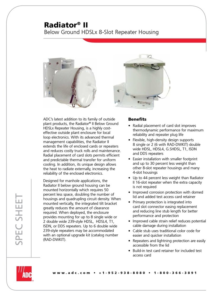
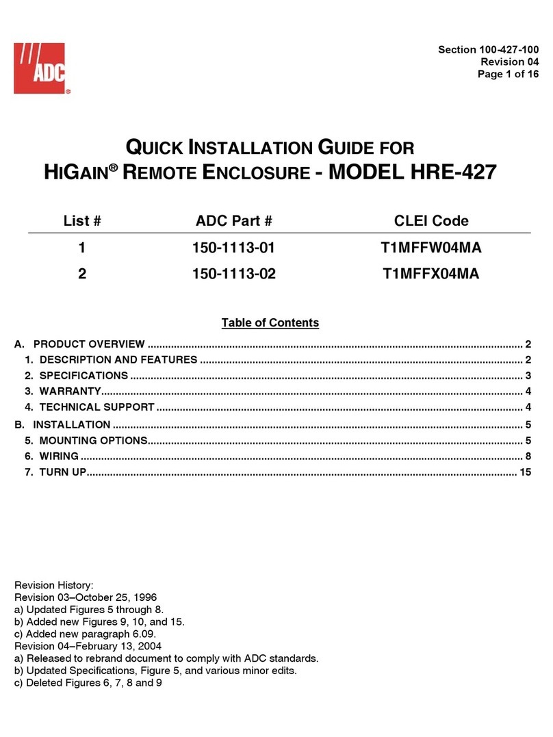
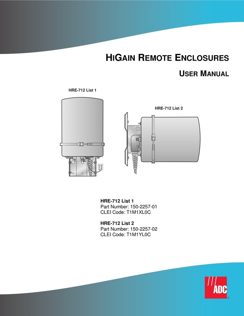
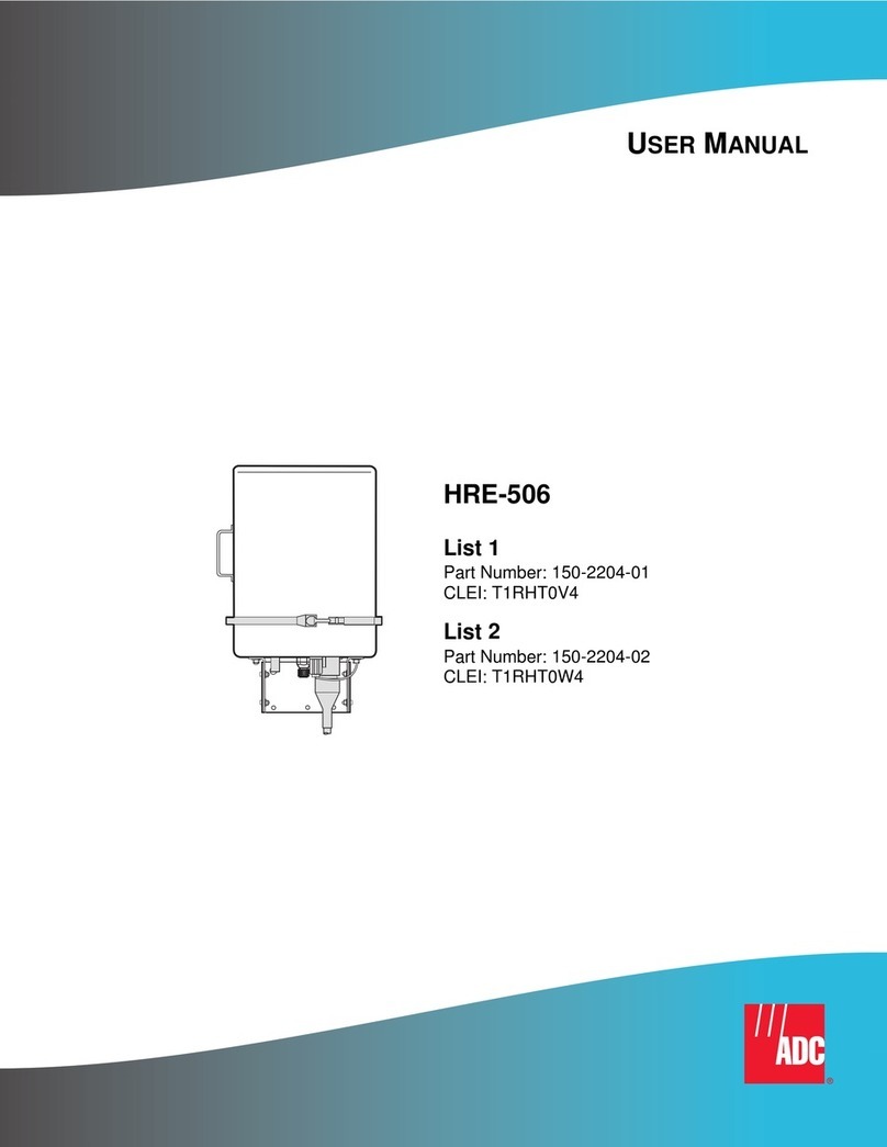
ADC HiGain HRE-819 User manual

HIGAIN OUTDOOR
DOUBLER ENCLOSURE
HRE-819 List 1 and List 2
Product Catalog: 150-819-100-03
CLEI: T1RHEE04 and T1RHEF04

150-819-100-03
ii June 19, 1998 HRE-819
Revision History of This Manual
Copyright
June 19, 1998
© 1998 ADC DSL Systems, Inc. All rights reserved.
Trademark Information
ADC is a registered trademark of ADC Telecommunications, Inc. HiGain is a registered trademark of ADC DSL Systems, Inc.
No right, license, or interest to such trademarks is granted hereunder, and you agree that no such right, license, or interest
shall be asserted by you with respect to such trademark.
Other product names mentioned in this document are used for identification purposes only and may be trademarks or
registered trademarks of their respective companies.
Disclaimer of Liability
Information contained in this document is company private toADC DSL Systems, Inc.,and shall not be modified, used, copied,
reproduced or disclosed in whole or in part without the written consent of ADC.
Contents herein are current as of the date of publication. ADC reserves the right to change the contents without prior notice.
In no event shall ADC be liable for any damages resulting from loss of data, loss of use, or loss of profits, and ADC further
disclaims any and all liability for indirect, incidental, special, consequential or other similar damages. This disclaimer of
liability applies to all products, publications and services during and after the warranty period.
Revision Release Date Revisions Made
01 February 2, 1998 Initial release
02 July 9, 1998 New illustrations, modifications to text.
03 October 14, 2002 ADC rebranding

150-819-100-03 Conventions Used in This Specification
HRE-819 June 19, 1998 iii
CONVENTIONS USED IN THIS SPECIFICATION
Two types of messages, identified by icons, may appear in the text:
INSPECTING SHIPMENT
Upon receipt of the equipment:
•Unpack each container and visually inspect it for signs of damage. If the equipment has been damaged in
transit, immediately report the extent of damage to the transportation company and to ADC. Order
replacement equipment, if necessary.
•Check the packing list to ensure complete and accurate shipment of each listed item. If the shipment is
incomplete or irregular, contact ADC as described in the Warranty. If you must store the equipment for a
prolonged period, store the equipment in its original container.
Notes contain information about special circumstances.
Cautions indicate the possibility of equipment damage or personal injury.

Inspecting Shipment 150-819-100-03
iv June 19, 1998 HRE-819

150-819-100-03 Table of Contents
HRE-819 List 1 and 2 July 9, 1998 v
TABLE OF CONTENTS
Overview ____________________________________________________________________________ 1
Enhanced Features .............................................................................................................................1
Standard Features...............................................................................................................................1
Description.........................................................................................................................................2
Mechanics............................................................................................................................2
Enclosure Base ....................................................................................................................4
Enclosure Housing...............................................................................................................4
Gel-filled Stub - HRE-819 List 1 Only ...............................................................................5
Air-filled Stub - HRE-819 List 2 Only................................................................................5
Pressurization.......................................................................................................................6
Air Bypass Valve ..................................................................................................6
Pressure-relief Valve and Air Stem.......................................................................7
Installation___________________________________________________________________________ 8
Unpacking..........................................................................................................................................8
Installing the Enclosure......................................................................................................................9
Manhole Installation............................................................................................................9
Aerial Installation ..............................................................................................................10
Splicing the Stub Cable....................................................................................................................11
Order Wire .......................................................................................................................................13
Through-Connecting........................................................................................................................14
Installing Doublers and Repeaters ...................................................................................................14
Wiring................................................................................................................................15
General Deployment Rules................................................................................................17
Maintenance ________________________________________________________________________ 18
Protector Extraction .........................................................................................................................18
Protector Installation........................................................................................................................18
Removing and Replacing Broken Cover Bolts................................................................................19
Replacement Parts............................................................................................................................20
Appendix A - Specifications____________________________________________________________ 21
Environment.....................................................................................................................................21
Dimensions.......................................................................................................................................21
Appendix B - Abbreviations ___________________________________________________________ 22
Appendix C - Product Support _________________________________________________________ 23
Bar Code Label and Configuration Number....................................................................................23
Table of Contents 150-819-100-03
vi July 9, 1998 HRE-819 List 1 and 2

150-819-100-03 Overview
HRE-819 List 1 and 2 July 9, 1998 1
OVERVIEW
This document describes the ADC®HiGain®Outdoor Mini and Micro Doubler Enclosures HRE-819 List 1 and
HRE-819List 2. The primaryapplication of the HRE-819 enclosure is to house HiGain Doubler units in a HiGain
repeaterless T1 transmission system. The HRE-819 is either a refurbished or originally manufactured AT&T
outdoor enclosure that has been enhanced to house up to:
•Twelve HiGain full-payload, T1 doublers (HDU-439 or HDU-409) or
•Twelve fractional T1 doublers (HDU-219) or
•Twelve 239 T1 repeaters or
•Twelve of any combination of these units
ENHANCED FEATURES
The HRE-819 has enhanced the standard AT&T 819 enclosure case in the following ways:
•Twelve, double-wide T1 239 slots for doublers or T1 repeaters
•Modified single 30-foot stub (54 pair, four group, quad S-screened)
•Enhanced thermal dissipation capabilities
STANDARD FEATURES
•Rack-mount or pole mount capability
•Primary surge suppression across all ports in every slot
•Support for pressure contactor alarm card
The cap, coil, filter, and type B protector functions are not supported.

Overview 150-819-100-03
2 July 9, 1998 HRE-819 List 1 and 2
DESCRIPTION
The HRE-819 List 1 is an AT&T-equivalent 819B1 or 819B2 outdoor enclosure with a gel-filled stub. The
HRE-819 List 2 is an AT&T-equivalent 819A1 or 819A2 outdoor enclosure with an air-filled stub. Figure 1
shows the HRE-819.
Figure 1. HRE-819 Outdoor Doubler Enclosure
Mechanics
The HRE-819 mechanics comply with standard AT&T 819 enclosure cases. The HRE-819 case
(Figure 2 on page 3) is composed of three basic subassemblies:
•An 81-type enclosure base
•A protected 89-type enclosure housing
•Removable access lids
The housing has two separate chambers. Each chamber has six double-wide slots and is accessed by a removable
lid. The HRE-819 family includes two types of lids and four types of bases. Table 1 on page 3 lists the type of
lids and bases and shows which ones are used for the HRE-819 List 1 and the HRE-819 List 2.

150-819-100-03 Overview
HRE-819 List 1 and 2 July 9, 1998 3
.
Figure 2. Enclosure Base and Housing
You can build the gel-filled List 1 unit with two regular-sized lids (a 2-inch deep, AT&T #842301483) or two
deep-dish lids (a 3.5-inch, AT&T 842301491). The List 1 requires an 81B1-1H base since it does not have an air
bypass valve.
You can build the air-filled List 2 unit only with the 2-inch deep lid and either the single-stub base (81A1-1H) or
a dual-stub base (81A1-1H or 81A2-2H). When you use a dual-stub base, the stub access opening adjacent to the
air cutoff valve is plugged.
Table 1. HRE-819 Mechanics
HRE-819 List Number
LID BASE
2-inch AT&T
#842301483 3.5-inch AT&T
#842301491 81B1-1H 81A1-1H 81A1-2H 81A2-2H
HRE-819 List 1, Gel X X X
HRE-819 List 2, Air X X X X
Housing
Housing base
Housing lids

Overview 150-819-100-03
4 July 9, 1998 HRE-819 List 1 and 2
Enclosure Base
The HRE-819 enclosure base is a molded plastic unit. The base contains the airbypass valve, pressure relief valve,
order wire port, stub cable, and mounting hardware.
In the event of damage to the housing, the housing can be detached from the base and replaced. This precludes the
need to blow the splice case and resplice a new unit stub into the main feeder cables. Whenever the base and
housing are separated and then reattached, torque the connecting bolts to 40 inch-pounds in the sequence shown
in Figure 3.
Figure 3. Sequence for Torquing the Base Connecting Bolts
Enclosure Housing
The enclosure housing (Figure 4 on page 5) is a molded plastic unit which has two separate chambers. Each
chamber has six double-wide slots and a slot for the maintenance pressure contactor plug. Each plug-in slot
contains connectors that accommodate both the plug-in unit and its associated protectors.
Seal the housing covers to the housing with a reusable gasket, which forms an airtight seal when the lid bolts are
properly torqued to 40 inch-pounds in the sequence inscribed on the lid (Figure 4 on page 5).
OW13
9
8
5
4
1
2
3
6
7
10
11
14
12
Stub

150-819-100-03 Overview
HRE-819 List 1 and 2 July 9, 1998 5
.
Figure 4. HRE-819 Housing
Gel-filled Stub - HRE-819 List 1 Only
The gel-filled, screened, 54-pair, 24-AWG cable stub on the List 1 unit is equivalent to an ALP FSS-PIC
filled-core telephone cable. It has a foam skin insulation with a single, filled jacket intended for buried, aerial,
and duct applications. Each conductor has a dual insulation consisting of an inner coating of natural,
insulating-grade, high-density, cellular polyethylene covered by an outer skin of color-coded, high-density, solid
polyethylene. Standard color codes are used for pair identification with color compounds chosen for electrical
balance and permanency (See Figure 9 on page 12). The cable complies with the requirements of ANSI/ICEA
S-84-608-1994. The outside diameter of the cable is 0.85 inches.
Air-filled Stub - HRE-819 List 2 Only
The plastic-insulated single-jacketed air-core cable stub on the List 2 unit is intended for buried, aerial, and duct
applications. Conductors are insulated with solid, high-density polyethylene. Standard color codes are used for
pair identification with color compounds chosen for electrical balance and permanency. The cable complies with
the requirements of ANSI/ICEA S -85-625-1996. The outside diameter of the cable is 0.85 inches.
1
1
17
2
2
2
8
3
3
9
P
10
5
5
5
11
6
6
6
12
Stub
Desiccant space
Lid-mounting
bolt holes
Torquing sequence
Pressure slot
Desiccant space
Desiccant space
6
4
4
4
Desiccant space
3

Overview 150-819-100-03
6 July 9, 1998 HRE-819 List 1 and 2
Pressurization
Figure 5 shows the pressurization valves. One of the most noticeable external differences between the two
enclosures is that the air bypass valve is absent from the gel-core model, HRE-819 List 1.
Figure 5. Pressurization Valve Locations
Air Bypass Valve
List 1 enclosures (gel-filled stub) are intended for above-ground applications and applications requiring the stub
to be spliced to non-pressurized, air core cables. Therefore, the List 1 enclosures do not have an air bypass valve.
List 2 enclosures (air-filled stub) are intended for man-hole applications. The List 2 enclosures are equipped with
an air bypass valve which is used to retain static pressure within the base and to control the inlet air supply that is
pumped from the main feeder cable through the 30-foot (9.144 M) stub into the HRE-819 enclosure.
•To shut off the inlet air supply, turn the air bypass valve counter-clockwise one-quarter turn away from the
housing.
•To turn on the inlet air supply, turn the air bypass valve clockwise one-quarter turn towards the housing.

150-819-100-03 Overview
HRE-819 List 1 and 2 July 9, 1998 7
Pressure-relief Valve and Air Stem
The pressure-relief valve keeps the internal pressure between 12 and 25 PSI. The air stem is a threaded Schraeder
valve (similar to a car tire valve) and cap. Use it to pressurize the enclosure from a local pressure source or to
measure the enclosure’s internal pressure through a pressure gauge or to relieve the internal pressure prior to
opening and removing the cover by removing the air stem valve core (pin).
List 1 and List 2 units are filled with nitrogen and pressurized before shipment. The internal
pressure must be relieved every time the cover is removed from the units. Failure to do so may
cause personal injury or equipment damage. Before shipment, the List 2 stub is also
pressurized, separately from the enclosure, through an air stem valve located in the end of the
stub.

Installation 150-819-100-03
8 July 9, 1998 HRE-819 List 1 and 2
INSTALLATION
This section describes the unpacking and installation procedures for the HRE-819 List 1 and 2.
UNPACKING
1Remove the HRE-819 from its shipping carton.
2Inspect the enclosure for shipping damage and report any damage to the carrier immediately.
3Perform an inventory to verify that all equipment listed on the packing list is present.
•HTC -439 test card
•HTC-439 technical practice
•Hardware installation kit containing:
Four 1/2-13 x 1-1/2T-bolts
Four 1/2-13 hex nuts
Four 17/32 I.D. flat washers
Two 1/4-20 x 7/16 shoulder screws
Two mounting brackets
An HTC-439 ADC test card is included with every HRE-819. This unit is found in a separate box
inside the HRE-819 shipping carton. The test card provides an easy-to-use way of accessing
and testing the four cable pairs connected to every HRE-819 slot. The test card is provided free
of charge for your convenience.

150-819-100-03 Installation
HRE-819 List 1 and 2 July 9, 1998 9
INSTALLING THE ENCLOSURE
Manhole Installation
The enclosure base has mounting brackets with four 9/16-inch diameter mounting holes spaced 13-1/2inches
vertically by 7-1/2inches horizontally. The hole spacing is consistent with the mounting slot spacing of standard
manhole racks.
1Lower the housing and attached stub cable into the manhole.
2Install and secure the base on cable racks as shown in Figure 6. The order wire terminal is located at the stub
cable end of the base unit. When cases are mounted in tight quarters, be sure to mount the case so that this
terminal is easily accessible.
Figure 6. Manhole Installation

Installation 150-819-100-03
10 July 9, 1998 HRE-819 List 1 and 2
Aerial Installation
To mount the doubler enclosure on a pole, use a 131B T-bracket and mounting bar assembly (ADC Part Number
132-1026-01), asshown in Figure 7. This assembly allows the case to be mounted with the stub cable up or down.
Figure 7. Vertical Pole Mounting at an Aerial Location
1Loosely install two of the T-bolts, nuts, and washers in one of the case-mounting brackets.
•For mounting with stub up, install these bolts in the mounting bracket closest to the stub.
•For mounting with stub down, install these bolts in the mounting bracket farthest from the stub. The bolts
engage the slots of the upper bar of the 131B T-bracket and support the case while you are installing the
lower mounting bolts.
2Select a place for the 131B T-bracket. It can be mounted at any height on a pole, preferably near the aerial
cableor approximately6feet abovegroundlevel for easyaccess whenusedwith buriedor undergroundcable.
3Drill a 3/4-inch diameter hole through the pole at the selected height.
4Use the 5/8-inch diameter suspension bolt, plus curved washers and a square nut, to fasten the top of the
131B T-bracket to the pole through the 3/4-inch hole.
All necessary bolts, nuts and washers are included in the hardware installation kit.
Lug screw
Case-mounting
brackets
T-bolt
Suspension bolt
131B T-bracket
131B Mounting bar
Pole

150-819-100-03 Installation
HRE-819 List 1 and 2 July 9, 1998 11
5Use the 1/2-inch lug screw at the bottom to fasten the mounting bar to the T-bracket and to keep the
131B T-bracket vertical on the pole.
6Lift the case. (The recommended way to lift the case is to use a sling attached through the opening in the
doubler enclosure.) Secure the case to the mounting bracket with the four T-bolts.
7Splice the stub. (See “Splicing the Stub Cable” on page 11). Enclosure cases mounted above ground can be
spliced to either air-filled core cable or gel-filled core cable.
•Enclosure cases spliced to air-core cable should be maintained under pressure from the cable. (See
“Pressurization” on page 6.)
•Enclosure cases spliced to gel-filled cable above ground can be left unpressurized except in flood areas
where static pressurization is recommended. (See “Air Bypass Valve” on page 6.)
8Ground the enclosure.
All pole-mounted doubler enclosures must be grounded. Install a No. 6 AWG copper ground wire between
the case mounting bracket farthest from the stub cable and a 5-foot ground rod driven into the ground.
SPLICING THE STUB CABLE
1Locate the splice case.
2Prepare the cable sheaths to prevent sharp edges from damaging the DEPIC insulation according to the
following steps. Figure 8on page 12 shows the splice preparation.Figure 9 on page 12 shows the cross section
of the stub.
aCut the screen to length.
bFlatten the screen as shown in Figure 8 on page 12.
cFold the end of the screen on itself three times.
dReform the screen (unflatten) around the binder unit.
eWrap the folded end of screen with vinyl tape.
Doubler enclosure stubs withshields bounded to a properly grounded main cable shield do not
require this additional ground wire. Noise due to ground loops could occur if the case is
grounded both places.
Ensure that the stub cable is properly bonded to the shield of the main cable if this is the only
means by which the double case is grounded.
The stub’s screen should not be grounded nor should it be connected to other screens.

Installation 150-819-100-03
12 July 9, 1998 HRE-819 List 1 and 2
Figure 8. Splice Preparation
3Before splicing the stub cable to the main cable, test all cable pairs designated for immediate or future use for
pair continuity and pair identification.
Figure 9. Cross Section of Quad S-Screened Stub at Splice

150-819-100-03 Installation
HRE-819 List 1 and 2 July 9, 1998 13
4Splice the stub cable to the main cable as outlined in Figure 10.
Figure 10. Enclosure Wiring
ORDER WIRE
The order wire is brought in on the G-W pair. The order wire access port (Figure 6 on page 9) provides access to
this pair.
ADC does not supply the optional 1000A order wire terminals. These are available from
third-party vendors.
P102
J102
J105
P105
J104
P104
P101
J101
J103
P103
Maintenance
pairs Binder
unit
colors
Base
Interface
connectors
Housing
Typical repeate
r
Typical doubler
Quad-screened
cable stub
FieldCO
BR-W
Splice Splice
G-WO-W
BL-W
Side 1
Side 2

Installation 150-819-100-03
14 July 9, 1998 HRE-819 List 1 and 2
THROUGH-CONNECTING
The method of through-connecting bypasses the housing and connects the pairs through the base. This allows
enclosure cable pairs to bypass the housing and be extended through it for access downstream from the HRE-819.
Through-connecting is accomplished by mating the 710-type connectors in the base as shown in Figure 11. The
maintenance pairs that terminate in J105 are not connected through.
Figure 11. Through Connections in Base
INSTALLING DOUBLERS AND REPEATERS
1For List 2 units, close the air bypass valve by turning the air bypass valve counter-clockwise 1/4turn away
from the housing.
2Depressurize the unit by removing the valve core (pin) in the air stem.
3Remove the two housing lids by loosening all twelve bolts with a 9/16-inch hand-held hex nut driver.
4Install the doublers and repeaters into the available slots.
5Make sure all sealing surfaces are clean and free of dirt and moisture.
6Place the lids on the housing.
7Treat the captive bolt threads with the antiseize compound.
To avoid injury and possible damage to the HRE-819, two people should remove it from its
container: one person should handle the enclosure, the other should handle the stub.
When handling the HRE-819 enclosure, always assume it is pressurized.
Replace the four desiccant bags (shown in Figure 4) each time the housing is entered. Place
the desiccant in any empty slot or between occupied slots as space permits. Flash test the
enclosure for leaks each time it is closed.
J105 P102 to J104 P101 to J103
Cable stub
Base
This manual suits for next models
1
Table of contents
Other ADC Enclosure manuals

ADC
ADC HIGAIN HRE-712 List 1 User manual

ADC
ADC HiGain HRE-206 List 1 Instructions for use

ADC
ADC HRE-454 User manual

ADC
ADC OmniReach FDH 3000 User manual

ADC
ADC HiGain HRE-427 User manual

ADC
ADC TrueNet Rack Mount Fiber Enclosures RMG... User manual

ADC
ADC HiGain HRE-504 User manual

ADC
ADC FRE-765 User manual

ADC
ADC HiGain HRE-500 List 1 User manual

ADC
ADC Fiber Optic Wall Box FL1000 Series Operating and safety instructions